
Related Manuals for Rain Bird PT3002


Summary of Contents for Rain Bird PT3002
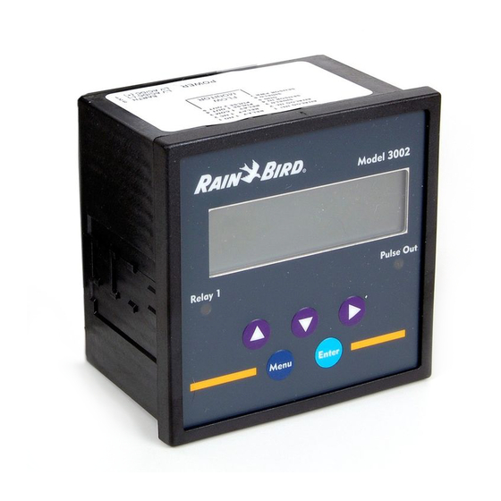
- Page 1 PT3002 Flow Sensor Transmitter Installation and Programming Instructions Instrucciones de instalación y programación...
-
Page 2: Table Of Contents
. . . . . . . . . . . . . . . . . . . . . . . . . . . . . . . . . . . . . . . . . . . . . . . . . . . . . PT3002 Flow Sensor Transmitter • Installation and Programming Instructions... -
Page 3: Wiring Instructions
PT3002 PT3002 Wiring Instructions NOTE: Refer to the PT3002 Flow Monitor and NEMACAB Installation sheet for more detailed instructions. Wire red wire from flow sensor to terminal four on blue terminal block with seven terminals. Wire black wire from Flow... -
Page 4: Using A Normally Closed Master Valve
SENSOR PORT Pulse Decoder the normally open master valve and closing it. Link MIB Board COM LINE Site Satellite 24 Volt Power Supply PT3002 PT3002 PT3002 Power Supply blue PT3002 Flow Sensor Transmitter • Installation and Programming Instructions (-) (+) blue/white... -
Page 5: For Output To Maxicom
Power CCU and satellite Controller. Wire Pulse 2 Out terminal five Supply to the blue / white wire of a pulse decoder. blue/white (-) (+) Pulse Decoder black PT3002 PT3002 PT3002 Flow Sensor Transmitter • Installation and Programming Instructions... -
Page 6: Initial Powerup
1. Press MENU to enter RESET SETUP DIAG Programming Mode. Press q to go to the When the PT3002 is first powered up, it runs through Password Screen. Menu Enter internal self checks, while displaying “PT3002 DIC ... - Page 7 15. Press u to Set then press ENTER Flow 1 sensor DICAL. (the PT3002 saves TYPE AVG DICAL the setting) Menu Enter Menu Enter PT3002 Flow Sensor Transmitter • Installation and Programming Instructions...
- Page 8 Sensor Calibration Menu Enter Screen) Note: See instructions pages 26 - 29 for Rain Bird Flow Sensor K & Offset information or instruction sheet included with Rain Bird Flow Sensors. Follow Step or Step to complete setup. 18. Press q to Set DI Sensor Cal.
-
Page 9: Step 2A
PWORD DSPY FLOW1 ENTER. Menu Enter Menu Enter 9. Press p . Relay 1 4. Press p for RLY1. SETUP LATCH SETPT RELP RLY1 PULSE AOUT1 Menu Enter Menu Enter PT3002 Flow Sensor Transmitter • Installation and Programming Instructions... - Page 10 Press ENTER Menu Enter when done. 13. Press ENTER. 17. The screen will Relay 1 0.00 GPM look as to the LATCH SETPT RELP 0.0 gal right. Menu Enter Menu Enter PT3002 Flow Sensor Transmitter • Installation and Programming Instructions...
-
Page 11: Step 2B
ENTER again. Menu Enter Menu Enter 4. Press p for RLY1. SETUP 9. Press p to SET Relay 1 RLY1 PULSE AOUT1 RATE. RATE CTIME Menu Enter Menu Enter PT3002 Flow Sensor Transmitter • Installation and Programming Instructions... - Page 12 13. Press MENU three Relay 1 (3) times to return RATE CTIME to Flow Total Screen. Menu Enter 14. The screen will 0.00 GPM look as to the 0.0 gal right. Menu Enter PT3002 Flow Sensor Transmitter • Installation and Programming Instructions...
-
Page 13: Resetting The 3002 After A High Flow Occurrence
4. Press MENU RESET RESET twice to return to twice to return to FLOW1 RLY1 FLOW1 RLY1 the GPM / Total the GPM / Total Screen. Screen. Menu Enter Menu Enter PT3002 Flow Sensor Transmitter • Installation and Programming Instructions... - Page 14 . . . . . . . . . . . . . . . . . . . . . . . . . . . . . . . . . . . . . . . . . . . . . . . . . . . . . PT3002 Flow Sensor Transmitter • Installation and Programming Instructions...
- Page 15 PT3002 PT3002 Instrucciones de cableado NOTA: Consulte el instructivo del monitor de flujo PT3002 y NEMACAB para instrucciones más detalladas. Conecte el cable rojo del sensor de flujo a la terminal azul rojo cuatro del bloque de siete terminales. Conecte el cable...
- Page 16 MIB activando la válvula maestra que está normalmente COM LÍNEA abierta y cerrándola. Suministro Sitio de satélite eléctrico de PT3002 PT3002 24 voltios PT3002 Suministro de energía azul PT3002 Flow Sensor Transmitter • Installation and Programming Instructions (-) (+) azul/blanco...
- Page 17 Conecte el cable desde la azul/blanco salida de la terminal 5 del pulso 2 al cable azul/blanco de (-) (+) un decodificador de pulso. Decodi cador rojo de pulso negro PT3002 PT3002 PT3002 Flow Sensor Transmitter • Installation and Programming Instructions...
- Page 18 Enter una auto verificación interna, mientras en la pantalla contraseña. aparece “PT3002 DIC Initializing. " Al final de este ciclo la pantalla vuelve a su estado normal. 2. Utilice las teclas de Enter password flecha para ingresar Pantalla y teclado 0000 una contraseña de...
- Page 19 15. Presione u para gal usando p Flow 1 sensor fijar DICAL. ó q y después TYPE AVG DICAL presione ENTER (el PT3002 guarda la configuración) Menu Enter Menu Enter PT3002 Flow Sensor Transmitter • Installation and Programming Instructions...
- Page 20 Nota: Vea las instrucciones en las paginas 26 - 29 para información sobre el sensor K de flujo marca Rain Bird y la hoja de instrucciones ó información impresa incluida con Siga los pasos ó...
- Page 21 PWORD DSPY FLOW1 presione ENTER. Menu Enter Menu Enter 9. Presione p . Relay 1 4. Presione p para LATCH SETPT RELP SETUP RLY1. RLY1 PULSE AOUT1 Menu Enter Menu Enter PT3002 Flow Sensor Transmitter • Installation and Programming Instructions...
- Page 22 Presione ENTER al concluir. Menu Enter 13. Presione ENTER. Relay 1 17. La pantalla se LATCH SETPT RELP 0.00 GPM verá como a la 0.0 gal derecha. Menu Enter Menu Enter PT3002 Flow Sensor Transmitter • Installation and Programming Instructions...
- Page 23 ENTER de nuevo. Menu Enter 9. Presione p para 4. Presione p para Relay 1 fijar el rango (SET SETUP RLY1. RATE CTIME RATE). RLY1 PULSE AOUT1 Menu Enter Menu Enter PT3002 Flow Sensor Transmitter • Installation and Programming Instructions...
- Page 24 Relay 1 tres (3) veces RATE CTIME para regresar a la pantalla Flow Total. Menu Enter 14. La pantalla se 0.00 GPM verá como a la 0.0 gal derecha. Menu Enter PT3002 Flow Sensor Transmitter • Installation and Programming Instructions...
- Page 25 4. Presione MENU RESET RESET dos veces para dos veces para FLOW1 RLY1 FLOW1 RLY1 regresar a la regresar a la pantalla GPM / pantalla GPM / Total. Total. Menu Enter Menu Enter PT3002 Flow Sensor Transmitter • Installation and Programming Instructions...
- Page 26 For Tee Type Flow Sensors Rain Bird Models FS100B, FS150P, FS200P, FS300P or FS400P use the K & Offset chart below. Para sensores tipo Te de modelos Rain Bird FS100B, FS150P, FS200P, FS300P o FS400P utilice la tabla K & valores de la parte inferior.
- Page 27 Appendix B Apéndice B For Insert Type Flow Sensors Rain Bird Models FS350B or FS350SS Para sensores Rain Bird tipo inserto de modelos FS350B ó FS350SS Calibration Table for Pipe Sizes 3" through 36" Tabla de calibración para tuberías de 3” a 36”...
- Page 28 20.00" 17.938" 213.140 0.511 400-12,000 22" Std. Wt., Sch 20 22.00" 21.25" 301.975 0.621 500-15,000 Extra Strong, Sch 30 22.00" 21.00" 294.642 0.616 500-15,000 Sch 80 22.00" 19.75" 259.513 0.573 500-15,000 PT3002 Flow Sensor Transmitter • Installation and Programming Instructions...
- Page 29 36" Sch 10 36.00" 35.376" 882.855 1.040 1,500-45,000 Std. Wt. 36.00" 35.25" 876.227 1.035 1,500-45,000 Sch 20, Extra Strong 36.00" 35.00" 863.154 1.025 1,500-45,000 Sch 40 36.00" 34.50" 837.315 1.007 1,500-45,000 PT3002 Flow Sensor Transmitter • Installation and Programming Instructions...
- Page 30 Notes PT3002 Flow Sensor Transmitter • Installation and Programming Instructions...
- Page 31 Notes PT3002 Flow Sensor Transmitter • Installation and Programming Instructions...
- Page 32 Fax: (626) 852-7343 Rain Bird Technical Services Specification Hotline The Intelligent Use of Water ™ (800) RAINBIRD (1-800-724-6247) 800-458-3005 (U.S. and Canada) www.rainbird.com (U.S. and Canada) Registered Trademark of Rain Bird Corporation ® © 2010 Rain Bird Corporation 2/10 D39955...
Need help?
Do you have a question about the PT3002 and is the answer not in the manual?
Questions and answers