Table of Contents
Advertisement
Quick Links
Advertisement
Table of Contents

Subscribe to Our Youtube Channel
Related Manuals for Milltronics 160

Summary of Contents for Milltronics 160
- Page 1 IQ RADAR 160 January 2001 Instruction Manual PL-550 33455500 Rev. 3.1...
- Page 2 Contact SMPI Technical Publications at the following address: Technical Publications Siemens Milltronics Process Instruments Inc. 1954 Technology Drive, P.O. Box 4225 Peterborough, Ontario, Canada, K9J 7B1 Email: techpubs@milltronics.com For the library of SMPI instruction manuals, visit our Web site: www.milltronics.com © Siemens Milltronics Process Instruments Inc. 2001...
-
Page 3: Table Of Contents
Table of Contents General Information ..................5 About this Manual..................5 About IQ Radar 160/160 Ex..............6 Specifications ....................7 IQ Radar 160/160 Ex ................7 Installation....................... 11 Location ....................11 Dimensions: Standard Unit with Rod Antenna........12 Dimensions: Ex Unit with Rod Antenna ..........13 Dimensions: Threaded Rod.............. - Page 4 Horn Antenna or Wave Guide Still Pipe – ANSI Hole Pattern, 150#..72 Horn Antenna or Wave Guide Still Pipe DN Hole Pattern, PN16 ..72 Horn Antenna Sanitary Connection............73 Appendix IV ....................75 BZT Approval – English................75 BZT Approval – German Original Text ..........76 Index......................77 Page 4 IQ Radar 160/160 Ex PL-550...
-
Page 5: General Information
Operation describes the operation of the IQ Radar 160/160 Ex. Applications looks at the IQ Radar 160/160 Ex from a practical point of view, using a typical application example. Parameters lists the parameters available to you, with a description of their function and use. -
Page 6: About Iq Radar 160/160 Ex
About IQ Radar 160/160 Ex The IQ Radar 160/160 Ex is to be used only in the manner outlined in this manual. IQ Radar 160/160 Ex is a versatile process material level monitoring instrument. Material level measurement is achieved using advanced pulse radar techniques. -
Page 7: Specifications
Specifications Every attempt has been made to ensure the accuracy of these specifications, however Milltronics reserves the right to change them at any time. Contact your Milltronics representative for the most recent specifications. IQ Radar 160/160 Ex Power: AC version: 100/115/200/230 ±15% V ac... - Page 8 II for ac version; I for dc version pollution degree: Teflon is a registered trademark of Du Pont Not available for CENELEC EEx approval See Temperature Derating on page 69 and Approvals on page 9. Page 8 IQ Radar 160/160 Ex PL-550...
- Page 9 Canadian Registration Number (CRN) for pressure fittings Ontario, British Columbia, Alberta: OF6494.512 others pending 3A Sanitary Contact Milltronics for complete and up to date list of approvals. Programmer (remote keypad): enclosure: general purpose 67 mm w x 100 mm h x 25 mm d (2.6"...
- Page 10 Page 10 IQ Radar 160/160 Ex PL-550...
-
Page 11: Installation
For vessels with conical or parabolic tops, it is not advisable to mount the unit at the centre. Otherwise, the concavity of the top can focus echoes into the centre, giving false readings. Conical Flat Parabolic PL-550 IQ Radar 160/160 Ex Page 11... -
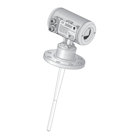
Page 12: Dimensions: Standard Unit With Rod Antenna
(16.3") * Flange thickness 25 mm (1") nominal. ** Standard length, 50 and 100 mm (2” and 4") extensions available. For information on temperature and pressure ratings, see Appendix III on page 69. Page 12 IQ Radar 160/160 Ex PL-550... -
Page 13: Dimensions: Ex Unit With Rod Antenna
(16.3") * Flange thickness 25 mm (1") nominal. ** Standard length, 50 and 100 mm (2” and 4") extensions available. For information on temperature and pressure ratings, see Appendix III on page 69. PL-550 IQ Radar 160/160 Ex Page 13... -
Page 14: Dimensions: Threaded Rod
Do not use wrenches or pliers. Hand tight only. Sealant must have ε r < 3 . We recommend a sealant such as Teflon paste or silicone compound. Page 14 IQ Radar 160/160 Ex PL-550... -
Page 15: Dimensions: Horn
(12.8”) (3”) horn 131 mm (5.16”) 225.8 mm Note: 100 mm 325.1 mm (4”) (12.8”) Signal amplitude increases with horn diameter, so use the largest size practical. 150 mm (6”) 200 mm (8”) PL-550 IQ Radar 160/160 Ex Page 15... -
Page 16: Dimensions: Waveguide Extension
(see P006 on page 53). 131 mm (5.16”) 225 mm (8.89”) 325 mm (12.8”) Note: 1. Maximum pressure 0.5 bar at 60 deg. C (140 deg. F) for sliding flange option. Page 16 IQ Radar 160/160 Ex PL-550... -
Page 17: Dimensions: Sanitary Horn
SS 304 SS 316 ferrule SS 304 SS 316 clamp SS 304 SS 316 gasket PTFE 50 mm (2”) clamp (supplied) horn 232 mm (9.13”) 100 mm (4”) clamp (optional) gasket (optional) ferrule (optional) PL-550 IQ Radar 160/160 Ex Page 17... -
Page 18: Dimensions: Sanitary Rod
Dimensions: Sanitary Rod 50 mm (2”), 80 mm (3”) or 100 mm (4”) with integral gasket ferrule (optional) clamp (optional) 406 mm (16”) Materials: SS304 standard nominal SS316 optional. Page 18 IQ Radar 160/160 Ex PL-550... -
Page 19: Dimensions: Waveguide
Dimensions: Waveguide 41.4 mm (1.69”) variable min: 100 mm (4.08”) max: 6000 mm (244.90”) waveguide 76.2 mm (3.0”) Note: you can connect multiple waveguides together (maximum 2). PL-550 IQ Radar 160/160 Ex Page 19... -
Page 20: Dimensions: Flanges
100 mm DN PN 16 220 mm 180 mm 18 mm 150 mm DN PN 16 285 mm 240 mm 22 mm 200 mm DN PN 16 340 mm 295 mm 22 mm Page 20 IQ Radar 160/160 Ex PL-550... -
Page 21: Mounting
The straight/taper transition of the rod should extend past the standpipe/vessel opening. Add extensions as required. • Refer to the Rod Extension Requirements table. • The unit in is improperly mounted. The Integral process seal MUST rest on customer flange as in PL-550 IQ Radar 160/160 Ex Page 21... - Page 22 You can use 1.5” or 2” threaded process connections. There are three thread types: NPT, BSP and G. 316 S.S. PTFE or UHMW-PE Wetted Parts: Metal: 316SS Polymeric: PTFE or UHMW-PE Internal O-ring: Viton Page 22 IQ Radar 160/160 Ex PL-550...
-
Page 23: Rod Assembly
50 mm 100 mm >150 mm (6”) n/r extension not required Consult Milltronics for assistance with standpipe sizes not listed. application not recommended for 50 mm (2”) i.d. standpipes greater than 100 mm (4”) long PL-550 IQ Radar 160/160 Ex... -
Page 24: Mounting: Rod Assembly
No antenna extensions required Stand pipes that are 8” or larger in diameter provide excellent signal conditions. These conditions allow for stand pipe lengths of up to 24” using the standard rod without any extensions. Page 24 IQ Radar 160/160 Ex PL-550... -
Page 25: Mounting: Manhole Covers
100 mm (4”) Mounting: Horn Antennas Usually, horns are mounted on short stand pipes. The end of the horn should protrude a minimum of 10 mm (0.5”) to avoid interference with the stand pipe. PL-550 IQ Radar 160/160 Ex Page 25... -
Page 26: Mounting: Waveguide Antenna
This option is recommended for products with ε lower than 3. The maximum range of this application is reduced to 10 m (33 feet). See P655 on page 58. vent hole minimum 80 mm (3”) Page 26 IQ Radar 160/160 Ex PL-550... -
Page 27: Mounting: Still Pipe Or Side Pipe
See P655 on page 58. Ensure there is a vent at the upper end of the surge pipe to equalize pressure and keep the liquid level in the pipe constant with level in the vessel. PL-550 IQ Radar 160/160 Ex Page 27... -
Page 28: Mounting: Horn With Waveguide Extensions
The horn must be connected to the IQ160 process flange. Note: The IQ160 maximum range of 15m is reduced by [0.64 x waveguide length]. Blanking and offset parameters will be set by Milltronics, see the device tag for values. Mounting: Sanitary Mounting There are two common sanitary mounting options;... -
Page 29: Mounting: Location/Beam Angle
Flat obstructions, and struts that are perpendicular to the emission cone, cause large false reflections. They reflect the radar signal with high amplitude. Round profile interfering surfaces diffuse reflections of the radar signals and cause false reflections with low amplitude. PL-550 IQ Radar 160/160 Ex Page 29... -
Page 30: Interconnection
Interconnection IQ Radar 160 Terminal Block AC version DC version SHLD L2/N IQ Radar 160 Ex Terminal Block AC version DC version Notes for both AC and DC versions: • mA, RS-485, wiring, 14 – 20 AWG, shielded copper wire. - Page 31 DC version 4-20 mA, to instrumentation RS-485, to host device to reliable earth ground V supply, see nameplate IQ Radar 160 Ex Wiring AC version DC version 4-20 mA, to instrumentation RS-485, to host device V supply, see nameplate enclosure Notes for AC version only: •...
- Page 32 Page 32 IQ Radar 160/160 Ex PL-550...
-
Page 33: Start Up
Start Up Overview The IQ Radar 160/160 Ex has two modes of operation: run and program . When the unit is powered, after installation procedures have been completed, it is programmed to start up in the run mode, to detect the distance from the antenna flange to the target in meters. -
Page 34: Hand Programmer
Refer to the Parameter Description that starts on page 53, for a list of the parameters available. When programming has been completed, the IQ Radar 160/160 Ex can be put into run by pressing, or exiting Dolphin. -
Page 35: Display
Display Aiming the Hand Programmer PL-550 IQ Radar 160/160 Ex Page 35... -
Page 36: Local Operation
0 to 100% of span reading questionable, appears during fail-safe operation auxiliary reading = normal reading = fail-safe operation Program Display parameter type parameter value (measurement of mA output) units parameter number Page 36 IQ Radar 160/160 Ex PL-550... - Page 37 Negative value Clear value Toggle between units and % on reading display End program session and Initiate and complete enable run mode program mode access “Distance” Parameter scroll-up Parameter scroll-down Enter the displayed value PL-550 IQ Radar 160/160 Ex Page 37...
-
Page 38: Local Programming
To Access Program Mode run mode Initial program starts Press at P000 To Access a Parameter Scroll Access Press Scroll up or down Direct Access e.g. P000 accessed Press index parameter field Press e.g. P005 accessed Page 38 IQ Radar 160/160 Ex PL-550... - Page 39 P001 = 1 Press Resetting a Parameter Value e.g. P001 = 1 Reset to factory value Press P001 = 3 To Access Run Mode: from program exit and return to run Press PL-550 IQ Radar 160/160 Ex Page 39...
- Page 40 Page 40 IQ Radar 160/160 Ex PL-550...
-
Page 41: Operation
Operation Overview The IQ Radar 160/160 Ex is a level measuring device for use with liquids and slurries. Using advanced pulse radar technology, the device calculates material level by first emitting a series of radar pulses and then analyzing their reflections. -
Page 42: Loss Of Echo
Loss of Echo A loss of echo occurs when the IQ Radar 160/160 Ex deems that the calculated measurement is unreliable, i.e. the confidence (P805) is less than the threshold (P804). -
Page 43: Analog Output
P801 should be increased accordingly. Analog Output The IQ Radar 160/160 Ex can be programmed to provide an analog output (P200) of 0 to 20 or 4 to 20 mA, and for proportional or inverse span. Programming Upon entering the Program mode, the analog output level holds its prior value. - Page 44 To program the unit for volume, set: • operation (P001) to level “1” (see page 53), • tank shape (P050) to a value other than 0 (see page 55), • other volume parameters (P051 to P053) as required. Page 44 IQ Radar 160/160 Ex PL-550...
-
Page 45: Run / Program
Run / Program When the IQ Radar 160/160 Ex changes from run to program , the unit no longer responds to the process. The last measurement is stored and the associated reading and mA output are held. As a courtesy, the unit reverts to the parameter last addressed during the previous program session. -
Page 46: Application Example: Asphalt In Storage Tank
(P006) the bottom. The maximum rate of filling or emptying is about 0.1 m/min. In the event of a loss of echo, the IQ Radar 160/160 Ex is to go into fail-safe Hi after 2 minutes. Span (P007) Asphalt build-up on the rod antenna does not effect performance. -
Page 47: Application Example: Horizontal Tank With Volume
(span) is 3.0 m from the bottom. The maximum rate of filling or emptying is about 0.1 m/min. In the event of a loss of echo, the IQ Radar 160/160 Ex is to go into fail-safe Hi after 2 minutes. 500 mm (20.4”) -
Page 48: Application Example: Juice Batch Tank With Sanitary Horn Antenna
The minimum distance from the antenna face to the target is limited by the near blanking, P800. Sanitary Antenna Options: • One-piece antenna/process seal • This provides an excellent mounting method, even on non-sanitary installations. 4” sanitary horn mixer existing 4” tri-clamp connection P006 P007 mixer Page 48 IQ Radar 160/160 Ex PL-550... -
Page 49: Application Example: Sliding Waveguide On Anaerobic Digesters
.46 m (18”) from the end of the horn. The raised position is for installation and maintenance. The lowered position is for horn operation. Program the unit for operation in the lowered position. P006 P007 PL-550 IQ Radar 160/160 Ex Page 49... -
Page 50: Application Example: Stand Pipe
3 or if extremely turbulent or vortex conditions exist. vent hole 100 mm (4”) diameter Note: For ε < 3, the lower 40 cm of vessel level may not be measurable. Page 50 IQ Radar 160/160 Ex PL-550... - Page 51 P655 Value 50 mm (2”) 0.827 80 mm (3”) 0.915 100 mm (4”) 0.955 150 mm (6”) 0.980 200 mm (8”) 0.990 Note: See the P655 table on page 58 for other pipe diameters. PL-550 IQ Radar 160/160 Ex Page 51...
- Page 52 Page 52 IQ Radar 160/160 Ex PL-550...
-
Page 53: Parameter Descriptions
If IQ Radar 160/160 Ex cannot keep up with the rate of level change, select a faster rate. If the reading bounces around an average value, select a slower rate. - Page 54 243 = rod + 150 mm extension (50 + 100 mm) Notes: • Setting this parameter automatically configures the offset correction, P652. • Horn antennas and waveguide/horn combinations will come from the factory with P652 pre-set and P004 set to 240. Page 54 IQ Radar 160/160 Ex PL-550...
- Page 55 P050 Tank Shape This parameter, in conjunction with parameters P051, P052 and P053, enable the IQ 160/160 Ex to show readings based on reservoir volume (rather than level). Enter the Tank Shape value that matches the monitored vessel or reservoir.
- Page 56 Example If max. volume = 3650 m , enter 3650. If max. volume = 267500 gallons, enter 267.5 (1000's of gallons). Enter the volume of the tank at full (Factory = 1) Page 56 IQ Radar 160/160 Ex PL-550...
- Page 57 2 = 4 to 20 mA 3 = 20 to 0 mA 4 = 20 to 4 mA P341 Run Time View the accumulated number of days the IQ Radar 160/160 Ex has been operating. PL-550 IQ Radar 160/160 Ex Page 57...
- Page 58 The propagation factor is constant for a given pipe diameter, or can be determined by comparing the radar distance reading to the actual process material distance (measured from the face of the IQ 160 flange). p.f. = actual distance IQ 160 distance e.g.
- Page 59 Select 1 for most applications and all mounting locations except the centre of the vessel. Select 6 for the centre of the vessel mounting location and for still pipes and waveguide antennas used as still pipes. PL-550 IQ Radar 160/160 Ex Page 59...
- Page 60 Selects the TVT profile applied to the echo profile. Entry: 1 = reserved 2 = reserved 3 = reserved 4 = Smooth 2 (factory – contact Milltronics for assistance with other selections) 5 = reserved 6 = reserved P900 Software Revision Displays the EPROM software revision level.
- Page 61 P923 Distance Measurement Displays the reading measurement as though the unit were programmed to read distance (P001 = 3) P999 Master Reset Resets parameters to their factory setting. initiate reset Press reset complete PL-550 IQ Radar 160/160 Ex Page 61...
- Page 62 Page 62 IQ Radar 160/160 Ex PL-550...
-
Page 63: Troubleshooting
• physical damage stilling well • excessive foam • relocate • use a defoamer • re-locate IQ Radar IQ Radar 160/160 Ex Reading does processing wrong echo, 160/160 Ex not change, but • check standpipe for i.e. vessel wall, or... -
Page 64: Maintenance
Requirements on page 23 • Internal seam in • Inspect and remove seam standpipe Maintenance The IQ Radar 160/160 Ex requires no maintenance or cleaning; however, a program of periodic checks is advised. Page 64 IQ Radar 160/160 Ex PL-550... -
Page 65: Appendix I
Near Blanking Offset Correction Operation Propagation Factor Range Extension Reading Measurement Run Time Software Revision Space Measurement Span Tank Dimension ‘A’ Tank Dimension ‘L’ Tank Shape TVT Type Units accessible only by service personnel. PL-550 IQ Radar 160/160 Ex Page 65... - Page 66 Page 66 IQ Radar 160/160 Ex PL-550...
-
Page 67: Appendix Ii
Near Blanking Range Extension Confidence Threshold Echo Confidence Echo Strength Algorithm Echo Marker Trigger TVT Type Long Shot Number* Software Revision Memory mA Output Value Reading Measurement Material Measurement Space Measurement Distance Measurement PL-550 IQ Radar 160/160 Ex Page 67... - Page 68 Page 68 IQ Radar 160/160 Ex PL-550...
-
Page 69: Appendix Iii
60 °C, then the maximum process temperature allowable at the flange is 100 °C process temperature in degrees Celsius at IQ 160/160 Ex flange Note: UHMW-PE is limited to a maximum continuous service temperature of 80°C / 176°F... -
Page 70: Rod Antenna Ansi Hole Pattern, 150
Rod Antenna DN Hole Pattern, PN16 temperature (•C) 50mm 80mm 100mm 150mm UHMW-PE antennas are rated to a maximum of 80°C (176°F) of continuous duty. Customer to provide adequate bolting to retain vessel pressure and provide sufficient sealing. Page 70 IQ Radar 160/160 Ex PL-550... -
Page 71: Rod Antenna Threaded Connection
UHMW-PE antennas are rated to a maximum of 80°C (176°F) of continuous duty, however, they can be used for periods up to 3 hours at temperatures up to 120°C (248°F) at 1 bar pressure. PL-550 IQ Radar 160/160 Ex Page 71... -
Page 72: Horn Antenna Or Wave Guide Still Pipe - Ansi Hole Pattern, 150
6” 8” Horn Antenna or Wave Guide DN Hole Pattern, PN16 temperature (•C) 80mm 100mm 150mm 200mm Customer to provide adequate bolting and flat-faced gasket to retain vessel pressure and provide sufficient sealing. Page 72 IQ Radar 160/160 Ex PL-550... -
Page 73: Horn Antenna Sanitary Connection
Horn Antenna Sanitary Connection 45.0 40.0 35.0 30.0 25.0 20.0 15.0 10.0 temperature (•C) 4” PTFE PL-550 IQ Radar 160/160 Ex Page 73... - Page 74 Page 74 IQ Radar 160/160 Ex PL-550...
-
Page 75: Appendix Iv
, 1996 (BGBI. I.S. 1120, the frequency 5.8 GHz is assigned as General Assignment for common use when employing transmission and reception radio plants distributed by MILLTRONICS LIMITED company, Worcester, England, and characterized by the designation “IQ Radar”. These radio plants are used for level measurement in chemical Industry plants with maximum radiating capacity of 30uW and a bandwidth of up to 1.3GHz. -
Page 76: Bzt Approval - German Original Text
Zwecken unter Verwendung anderer Geräte nicht aus. Die Funkanlagen sind wie folgt zu kennzeichnen: Bundesadler, Zulassungsnummer “BZT G750826K”, sowie der Name der Vertriebsfirma MILLTRONICS LIMITED, Worcester, England und der Typenbezeichnung “ IQ Radar ”. Im Rahmen dieser Frequenznutzung dürfen andere Telekommunikationsanlagen sowie andere Funkanlagen nicht gestört werden. -
Page 77: Index
Interface Specifications......7 Conical Tank ........11 IQ Radar 160 Ex Dimensions ..... 13 DC version ..........30 IQ Radar 160 Ex Terminal Block ..30 Dimensions .........12 IQ Radar 160 Ex Wiring...... 31 IQ Radar 160........12 IQ Radar 160 Terminal Block ..... 30 IQ Radar 160 Ex ......13... - Page 78 Calculated by equation ....58 P000, lock ...........53 Calculated by pipe diameter ... 58 P001, operation........53 Proper vs. Improper Mounting .... 21 P002, material ........53 Quick Start .......... 34 P003, measurement response ....53 Page 78 IQ Radar 160/160 Ex PL-550...
- Page 79 Storage Tank with Rod Antenna ..46 Tank ......... 11, 46, 47, 55 Conical ..........11 Flat ..........11 Height..........57 Length ..........57 Parabolic .........11 Shape..........55 Volume ..........56 Tank Dimension ‘A’ (P052) ....57 Tank Dimension ‘L’ (P053)....57 PL-550 IQ Radar 160/160 Ex Page 79...
- Page 80 Page 80 IQ Radar 160/160 Ex PL-550...
- Page 81 Siemens Milltr onics Process Instruments Inc.2000 Subject to change without priornotice Siemens Milltr onics Process Instruments Inc. 1954Technology Drive, P .O. Box 4225 Printed in Canada Peterborough, ON.Canada K9J 7B1 Tel: (705) 7 45-2431 Fax: (705) 7 41-0466 www.milltronics.com...
Need help?
Do you have a question about the 160 and is the answer not in the manual?
Questions and answers