Table of Contents
Advertisement
Quick Links
NOTE:
Please read all
instructions carefully
before using this product
Table of Contents
Safety Notice
Important Assembly
Information
Care and Maintenance
Parts List
Warranty
Ordering Parts
Model
ME-1017E
Retain This
Manual for
Reference
180501
OWNER'S
MANUAL
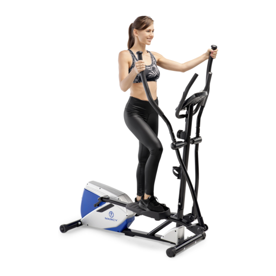
MAGNETIC ELLIPTICAL
IMPORTANT:
Please read this manual before commencing
assembly of this product.
2801 S. Towne Ave, Pomona, CA 91766
TRAINER
ME-1017E
®
IMPEX
INC.
Tel: 800- 999-8899
www.marcypro.com
support@impex-fitness.com
Advertisement
Table of Contents

Related Manuals for Marcy ME-1017E


Summary of Contents for Marcy ME-1017E
- Page 1 NOTE: Please read all instructions carefully before using this product MAGNETIC ELLIPTICAL TRAINER Table of Contents ME-1017E Safety Notice Important Assembly Information Care and Maintenance Parts List Warranty Ordering Parts Model ME-1017E Retain This Manual for Reference 180501 IMPORTANT: Please read this manual before commencing OWNER'S assembly of this product.
-
Page 2: Table Of Contents
COMPUTER INSTRUCTIONS EXERCISE GUIDELINES WARRANTY ORDERING PARTS BEFORE YOU BEGIN Thank you for selecting MARCY MAGNETIC ELLIPTICAL TRAINER ® ME-1017E by IMPEX INC. For your safety and benefit, read this manual carefully before using the equipment. As a manufacturer, we are committed to providing you with complete customer satisfaction. -
Page 3: Important Safety Notices
IMPORTANT SAFETY NOTICE This exercise equipment is built for optimum safety. However, certain precautions apply whenever you operate a piece of exercise equipment. Be sure to read the entire manual before you assemble or operate your equipment. In particular, note the following safety precautions: 1. -
Page 4: Warning Label Placement
WARNING LABEL PLACEMENT The warning labels shown here have been placed on the Base Frame. If the labels are missing or illegible, please call customer service at 1-800-999-8899 for replacements. Apply the labels in the location shown. © Impex Inc. www.marcypro.com... -
Page 5: Hardware Pack
HARDWARE PACK NOTE: The following parts are not drawn to scale. Please use your own ruler to measure the size. Q’TY DESCRIPTION DRAWING Carriage bolt M10*75 Curved washerФ10*Ф22 Domed nut M10 Hollow carriage nutФ8*20 Allen bolt M6*12 Flat washerФ10*Ф32 Lock washerФ10 Hex head bolt M10*20 D type washer Hex bolt M8*45... - Page 6 Washer Ф10*Ф22 Washer Φ27*Φ12.8 Allen bolt M8*16 Curved washer Ф8*Ф20 Hinge bolt L/R Wave washer Nut L/R Allen Key Allen key L8 Allen Key L6 Allen Key L4 © Impex Inc. www.marcypro.com...
-
Page 7: Components
COMPONENTS FOR ASSEMBLY NO:12/13 NO:52/53 NO:1 NO:9/51 NO:41L/R NO:48L/R NO:10 NO:11 NO:37L/R NO:39 NO:6/3 NO:35 NO:43 Q’TY PART NO. DESCRIPTION Main Frame 9/51 Front post/ Tension control knob w/cable 52/53 Bottom handlebar L/R 12/13 Top handlebar L/R Pedal tube L/R Fixed handlebar Front stabilizer/ Rear stabilizer Computer... -
Page 8: Assembly Instructions
ASSEMBLY INSTRUCTION STEP 1 1. Attach rear stabilizer (#3) to main frame (#1), tighten with two curved washers (#4), domed nuts (#5) and carriage bolts (#2). 2. Attach the front stabilizer (#6) to the main frame (#1), tighten with two carriage bolts (#2), curved washers (#4) and domed nuts (#5). - Page 9 STEP 2 1. Connect the extension lower sensor wire (#49) with the middle sensor wire (#55). 2. Turn the tension control knob w/cable (#51) to level 8, connect it to extension tension cable (#50). 3. Insert the front post (#9) into the main frame (#1) and secure using four Allen bolts (#47) and four curved washers (#54).
- Page 10 HOW TO CONNECT TENSION CONNECTOR Slide the Cable wire from the extension sensor wire Connector in between the opening on the wire holder on sensor wire Connector. Pull the extension sensor wire Connector backward and slide the wire through the slot on the bracket. Drop down the Connector so the fitting sits firmly on top of the bracket.
- Page 11 Step3 1. Attach the bottom handlebar L (#52) into the front post (#9), tighten with one D type washer (#29), washer (#26), lock washer (#27) and hex bolt (#28). 2. Repeat for bottom handlebar R (#53). 29 27 © Impex Inc. www.marcypro.com...
- Page 12 STEP 4 1. Attach pedal tube L (#41L) to the crank, secure using one nut (#60L), wave washer (#36), and hinge bolt L (#59L). 2. Slide bottom handlebar L (#52) into pedal tube L (#41L) then insert sleeve (#33). Insert hex bolt (#32) through sleeve (#33) then fasten and secure with one washer (#44) and aircraft nut (#34).
- Page 13 Step5 1. Insert the top handlebar L (#12) into the bottom handlebar L (#52), tighten with two hollow carriage nuts (#21) and Allen bolts (#22). Repeat for top handlebar R (#13). 2. Insert the hand pulse wire (#58) through front post (#09) and pull the hand pulse wire (#58) out of front post (#09).
- Page 14 Step6 1. Connect upper sensor wire from the back of computer (#10) to the middle sensor wire (#55). 2. C onnect lower pulse wire (#58) to upper pulse wire from the back of the computer (#10). Attach computer (#10) to bracket on front post (#09), tighten with four screws (#20). ©...
- Page 15 Step7 1. Attach computer (#10) to bracket on front post (#9), tighten with two screws (#20). 2. Attach top handlebar cover (#35) to the top handlebar L/R (#12/#13), tighten with four self- tapping screws (#23). 3. Attach bottom handlebar cover (#39) to the bottom handlebar L/R (#52/#53), tighten with two self-tapping screws (#30).
-
Page 16: Exploded Diagram
EXPLODED DIAGRAM 29 27 © Impex Inc. www.marcypro.com... - Page 17 © Impex Inc. www.marcypro.com...
- Page 18 ME-1016U PARTS LIST PART PART DESCRIPTION DESCRIPTION Main frame Hex bolt M8x1¾" Carriage bolt M10x3" Hex bolt M10x3" Rear stabilizer Sleeve Curved washer Ф¾" Aircraft nut M10 Domed nut M10 Top handlebar cover Front stabilizer Wave washer End cap for front stabilizer Pedal tube cover L/R End cap for rear stabilizer Belt...
- Page 19 Plastic spacer Screw M6x1" Flywheel Nut M8 Clip Spring Bearing Sensor bracket Axle for flywheel BB assembly Flange nut Pulley Flywheel adjuster Front chain cover L/R Magnetic assembly Crank L/R Spacer Main crank cover L/R Hex head bolt M8x4" Chain cover L/R COMPUTER FUNCTIONAL BUTTONS: MODE - Push down for selecting functions.
-
Page 20: Exercise Guidelines
Note: During the pulse measurement, the measured value may be higher than the actual pulse rate during the first 2~3 seconds, then will return to normal level. The PULSE Function value cannot be regarded as the basis of medical treatment. Press “MODE”... - Page 21 2. The Exercise Phase This is the stage where you put the effort in. After regular use, the muscles in your legs will become more flexible. Work to your targeted heart rate but it is very important to maintain a steady tempo throughout.
-
Page 22: Warranty
® IMPEX INC. LIMITED WARRANTY ® IMPEX Inc. ("IMPEX ") warrants this product to be free from defects in workmanship and material, under normal use and service conditions, for a period of two years on the Frame from the date of purchase. This warranty extends only to the original purchaser.
Need help?
Do you have a question about the ME-1017E and is the answer not in the manual?
Questions and answers