Table of Contents
Advertisement
Advertisement
Table of Contents

Related Manuals for Marcy MD-8851R


Summary of Contents for Marcy MD-8851R
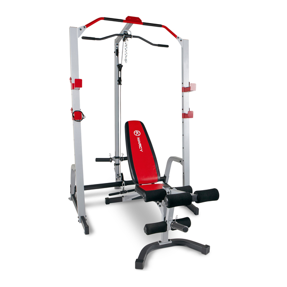
- Page 1 NOTE: Please read all instructions carefully before using this product ® MARCY DELUXE CAGE & BENCH Table of Contents MD-8851R Safety Notice Hardware Pack Assembly Instruction Parts List Warranty Ordering Parts Model MD-8851R Retain This Manual for Reference 170301 OWNER'S...
-
Page 2: Table Of Contents
MD-8851R Deluxe Cage & Bench. For your safety and benefit, read this manual carefully before using the machine. As the official representative for Marcy, we are committed to providing complete customer satisfaction. If you have any questions, or find missing or damaged parts, we guarantee you complete satisfaction through direct assistance from our factory. -
Page 3: Important Safety Notices
IMPORTANT SAFETY NOTICE PRECAUTIONS This exercise machine is built for optimum safety. However, certain precautions apply whenever you operate a piece of exercise equipment. Be sure to read the entire manual before you assemble or operate your machine. In particular, note the following safety precautions: 1. -
Page 4: Warning Label Placement
WARNING LABEL PLACEMENT... -
Page 5: Free And Training Area
FREE AND TRAINGING AREA REQUIREMENTS... -
Page 6: Cage Hardware Pack
CAGE HARDWARE PACK NOTE: The following parts are not drawn to scale. Please use your own ruler to measure the size. - Page 7 CAGE HARDWARE PACK NOTE: The following parts are not drawn to scale. Please use your own ruler to measure the size.
-
Page 8: Cage Assembly Instructions
CAGE ASSEMBLY INSTRUCTION Tools Required for Assembling the Machine: One Adjustable Wrench and Allen Wrenches. NOTE: It is strongly recommended that two or more people assemble this machine to avoid possible injury. STEP 1 (See Diagram 1) A.) Do not tighten Nuts and Bolts until instructed to do so. B.) Attach the Left Vertical Frame (#1) onto a Base Frame (#3). - Page 9 DIAGRAM 1...
- Page 10 STEP 2 (See Diagram 2) A.) Do not tighten the Nuts and Bolts until instructed to do so. B.) Attach the Lower Pulley Frame (#11) to the Cross Brace (#5). Secure it with two M10 x 2 ½” Carriage Bolts (#45), one 4 3/8” x 1 ¾” Bracket (#19), two Ø ¾” Washers (#55), and two M10 Aircraft Nuts (#57).
- Page 11 DIAGRAM 2...
- Page 12 CABLE LOOP DIAGRAM...
- Page 13 STEP 3 (See Diagram 3) A.) Attach the 92” Upper Cable (#42) to the open bracket under the Upper Frame (#13). B.) Attach a Pulley (#41) to the bracket. Secure it with one M10 x 1 ¾” Allen Bolt (#52), one Cable Retainer (#36), one cable Retainer Bushing(#37), two Ø...
- Page 14 DIAGRAM 3...
- Page 15 STEP 4 (See Diagram 4) A.) Attach the 110” Lower Cable (#43) to the open Pulley bracket on Lower Pulley Frame (#11). Secure it with one M10 x 1 ¾” Allen Bolt (#52), two Ø ¾” Washers (#55), and one M10 Aircraft Nut (#57).
- Page 16 DIAGRAM 4...
- Page 17 STEP 5 (See Diagram 5) A.) Attach the Left & Right Safety Catch (#7 & #8), the Left & Right Bar Catch (#9 & #10) onto the Left & Right Vertical Frame (#1 & #2). B.) Attach two Olympic Sleeves (#35) onto the Sliding Weight Post (#14). Attach a Spring Clip (#61) onto each Olympic Sleeve.
- Page 18 DIAGRAM 5...
- Page 19 MD-8851R WEIGHT RESISTANCE CHART Weight Plate Lat Pull Low Pulley Load even weights on each side of Sliding Weight Post Numbers are approximate. Actual weights may vary.
-
Page 20: Exploded Diagram
CAGE EXPLODED DIAGRAM... -
Page 21: Cage Parts List
CAGE PARTS LIST Q’ty KEY NO. DESCRIPTION M10 x 2” Allen Bolt Left Vertical Frame M10 x 1 ¾” Allen Bolt Right Vertical Frame M10 x 1” Allen Bolt Base Frame Diagonal Support Rivet Ø ¾” Washer Cross Brace Ø 1 ½” x Ø ½” Spacer Chin-up Bar Left Safety Catch M10 Aircraft Nut... -
Page 22: Multi-Purpose Bench Hardware Pack
MULTI-PURPOSE BENCH HARDWARE PACK NOTE: The following parts are not drawn to scale. Please use your own ruler to measure the size:... - Page 23 MULTI-PURPOSE BENCH HARDWARE PACK NOTE: The following parts are not drawn to scale. Please use your own ruler to measure the size.
-
Page 24: Multi-Purpose Bench Assembly Instructions
MULTI-PURPOSE BENCH ASSEMBLY INSTRUCTION Tools Required for Assembling the Machine: Two Adjustable Wrenches and Allen Wrenches. NOTE: It is strongly recommended that this machine be assembled by two or more people to avoid possible injury. STEP 1 (See Diagram 1) A.) Do not tighten Nuts and Bolts until instructed to do so. - Page 25 STEP 2 (See Diagram 2) A.) Attach the Incline Support (#8) to the middle side holes on the two Backrest Supports (#7). Secure it with one M10 x 6 7/8” Allen Bolt (#26), two Ø ¾” Washers (#35), and one M10 Aircraft Nut (#37). Do not tighten the Nut and Bolt yet.
- Page 26 STEP 3 (See Diagram 3) A.) Place the Backrest Board (#11) onto the Backrest Supports (#7). Secure it with four M8 x 1 5/8” Allen Bolts (#32) and 5/8” Washers (#36). B.) Place the Seat Pad (#10) onto the two Seat Brackets (#4). Secure it with four M8 x 1 1/8”...
- Page 27 STEP 4 (See Diagram 4) A.) Attach the Leg Developer (#5) to the open bracket on the Front Post (#2). Secure it with one M10 x 3” Allen Bolt (#29), two ¾” Washers (#35), and one M10 Aircraft Nut (#37). B.) Insert the Leg Developer Weight Post (#6) into the hole on Leg Developer.
-
Page 28: Exploded Diagram
BENCH EXPLODED DIAGRAM... -
Page 29: Multi-Purpose Bench Parts List
MULTI-PURPOSE BENCH PARTS LIST Q’ty KEY NO. DESCRIPTION Main Frame Front Post Rear Stabilizer Seat Bracket Leg Developer Leg Developer Weight Post Backrest Support Incline Support Front Stabilizer Seat Pad Backrest Board 5/8” x 1 1/8” End Cap Foam Tube Foam Roll Olympic Sleeve Foam Roll End Cap... -
Page 30: Warranty
LIMITED WARRANTY Pure-Tec. warrants this product to be free from defects in workmanship and material, under normal use and service conditions. Please refer to www.puretecfitness.com for warranty conditions. This warranty extends only to the original purchaser and is valid for home use only.
Need help?
Do you have a question about the MD-8851R and is the answer not in the manual?
Questions and answers