Industrial Scientific Ventis MX4 Product Manual
Hide thumbs
Also See for Ventis MX4:
- Operation manual (33 pages) ,
- Reference manual (21 pages) ,
- User manual (2 pages)

Related Manuals for Industrial Scientific Ventis MX4


Summary of Contents for Industrial Scientific Ventis MX4
- Page 1 Multi-gas Monitor Product Manual Set-up Operation Service Part Number: 17152357-1 Version 15...
-
Page 2: Table Of Contents
Hazardous Conditions, Poisons, and Contaminants ................4 General Usage ............................5 Agency-issued Conditions of Use and Warnings ..................5 Recommended Practices .......................... 6 ►Ventis MX4 Resources ..........................6 ►Ventis MX4 Capabilities ..........................7 ►Unpacking the Monitor ..........................7 Contents ..............................7 Hardware Features and Functions ...................... - Page 3 Diffusion Monitor ............................. 39 Sensor, Sensor Barrier, LCD, and vibrating motor replacement ............40 Battery Configuration ..........................45 ►Products, Specifications, and Certifications .................... 47 Ventis MX4 Accessories and Parts ......................47 Monitor Specifications ..........................47 Battery Specifications ..........................48 Operating Conditions ..........................48 Cold-weather Operation ..........................
-
Page 4: Copyright Notice
The information contained herein is believed to be accurate and reliable. Industrial Scientific Corporation accepts no responsibility for its use by any means or in any way whatsoever. Industrial Scientific Corporation shall not be liable for any expenses, costs by damage that may result from the use of the information contained within this document. -
Page 5: General Usage
(e.g., iNet Control or Accessory Software) or by manually configuring the instrument settings after docking. The Ventis MX4 is CSA certified according to the Canadian Electrical Code for use in Class I, Division 1 and Class I, Zone 1 Hazardous Locations within an ambient temperature range of T : -20°C to +50°C. -
Page 6: Recommended Practices
Contact your service representative immediately if you suspect that the Ventis MX4 is working abnormally. ►Ventis MX4 Resources The Ventis MX4 Product Manual is the primary resource, within a full suite of learning tools, developed for the monitor user. Its step-by-step “walk through” format covers everything from unpacking to set-up, operation, and service. All Ventis MX4 users should read and understand the Product Manual prior to unpacking or using the monitor. -
Page 7: Ventis Mx4 Capabilities
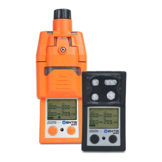
The Ventis MX4 is a portable multi-gas monitor. Offered as a diffusion monitor, it detects and measures gas(es) present in open space. To enable monitor use within confined space locations, the Ventis MX4 is also offered as an aspirated monitor. A pump module and battery accessories enable the conversion of either monitor for dedicated use in either confined or open spaces. -
Page 8: Hardware Features And Functions
*Some factory set sensor values subject to user changes. Warranty Card After unpacking, if any item is missing or appears to have been damaged, contact a local distributor of Industrial Scientific products or Industrial Scientific Corporation (for contact information, please see the manual’s last page). Monitor Overview ►... -
Page 9: Display Screen
Display Screen The Ventis MX4 Boot-up Screen, as shown below, serves to introduce all icons and the alpha-numeric items (e.g., 8.8.8) that can appear on the display when the monitor is in use, docked, or charging. Each display item is stationary, communicates unique information, and appears only when relevant to the task being performed. - Page 10 Peak: displayed when peak detection values are viewed. Alpha-numeric Definition display values Carbon Monoxide (CO) Methane (CH Sulfur Dioxide (SO Lower Explosive Limit. Display variations: “LEL” (English) “LIE” (French) “UEG” (German) Oxygen (O Nitrogen Dioxide (NO © 2018 Industrial Scientific Corporation...
-
Page 11: Alarms
→ When the latch alarm feature is enabled and the monitor goes into alarm, it will remain in alarm until the alarm condition no longer exists and the monitor user presses the ENTER button for one second. This applies only to gas-related alarms. © 2018 Industrial Scientific Corporation... - Page 12 Ventis™ MX4 Product Manual It is practical for the monitor user to be aware of the possible alarms prior to monitor set-up and use. The Ventis MX4 has four alarm and warning levels. A “system level” alarm generates the highest frequency tone and highest level visual and vibration signals.
- Page 13 Error codes 4XX to 5XX (404 shown here) indicate the monitor has detected a malfunction. The unit is not operational and and should be examined by a qualified technician or reported to Industrial Scientific for service or repair information. Critical Error Screen © 2018 Industrial Scientific Corporation...
-
Page 14: Monitor Set-Up
Three beeps sound every 30 seconds and the calendar and alarm icons display. The gas cylinder icon flashes. * The numeric mode display shows gas concentration values; the text mode display shows gas type names in place of gas values. ►Monitor Set-up © 2018 Industrial Scientific Corporation... -
Page 15: Batteries
*X indicates color and Y indicates approvals. Docking Stations, Chargers, and other Accessories Fully charge the monitor before first use. The lithium-ion equipped Ventis MX4 can be charged using any of the products listed below. Part Number Product... -
Page 16: Battery Charging
Power-on and -off To power-on the Ventis MX4, press ON/OFF/MODE and hold for three to five seconds. During the first ten to15 seconds the monitor is on, its firmware completes internal tests and the user sees or hears what is described and shown below. - Page 17 Countdown Screen simultaneously press ON/OFF/MODE and Displays the 20 second countdown, one second at a time, from 20 ENTER, hold for three seconds, and release. to one. Options : Enter gas monitoring mode Enter configuration mode © 2018 Industrial Scientific Corporation...
-
Page 18: Configuration
Security Code Language Selection Always-on Setting Shutdown In Alarm Setting Alarm on Dock Setting The Ventis MX4 can be configured manually as instructed below. Any changes made take effect immediately upon exiting the configuration mode. © 2018 Industrial Scientific Corporation... -
Page 19: Instructions
Zero Initiate Screen. For complete calibration instructions, proceed to the manual section, Zero, Calibration, and Bump Testing. LEL Type Set Screen Options © 2018 Industrial Scientific Corporation... - Page 20 ON/OFF/MODE buttons, respectively, to edit and set each sensor’s sensors is NOT installed, its position on low alarm value. the display is blank. After the alarm value is set for each installed sensor, press ON/OFF/MODE to advance to the High Alarm Set-point Screen. © 2018 Industrial Scientific Corporation...
- Page 21 Press ON/OFF/MODE to set the value and advance to the STEL Alarm Set-point Screen. TWA Interval Set-point Screen Displays the existing TWA interval. The value can be set from one to 40 hours, in increments of one. © 2018 Industrial Scientific Corporation...
- Page 22 The year is displayed beneath the day. After all values are set, press ON/OFF/MODE and advance to the Display Mode Set Screen. © 2018 Industrial Scientific Corporation...
- Page 23 If Bump Test In-field is enabled, the Bump Due Warning Option Bump Test In-field Option Screen Screen displays. Options 0 = Disable/off If the Bump Test In-field is disabled, the Alarm Latch Set 1 = Enable/on Screen displays. © 2018 Industrial Scientific Corporation...
- Page 24 ENTER button for one second. Press ENTER to edit the value, if needed. Latch Alarm Set Screen Press ON/OFF/MODE to set the value and advance to the Zero In-field Screen. Options 0 = Normal mode 1 = Latching mode © 2018 Industrial Scientific Corporation...
- Page 25 Press ENTER to edit the value, if needed. Options Press ON/OFF/MODE to set the value and advance to the Security 0 = display days since last calibration Code Set Screen 1 = display days until next calibration © 2018 Industrial Scientific Corporation...
- Page 26 Disable or enable alarm indicators when the unit is docked. Press ENTER to edit the value, if needed. Press ON/OFF/MODE to set the value and advance to the next configuration mode screen. Alarm on Dock Screen Options 0 = Disable/off © 2018 Industrial Scientific Corporation...
-
Page 27: Monitor Use And Service
These recommendations are based on field data, safe work procedures, industry best practices, and regulatory standards to help ensure worker safety. Industrial Scientific is not responsible for setting safety practices and policies. These policies may be affected by the directives and recommendations of regulatory groups, environmental conditions, operating conditions, instrument use patterns and exposure to gas, and other factors. -
Page 28: General Information
Industrial Scientific calibration gas(es), to prepare the monitor for first time use, and monthly (at a minimum) thereafter, to help ensure monitor accuracy. → Industrial Scientific also recommends that each monitor be zeroed and bump tested before each use with a known certified concentration(s) of Industrial Scientific calibration gas(es). -
Page 29: Supplies
*Shipped with monitor. **Industrial Scientific recommends 1) the use of positive flow regulators with a flow rate of .5 LPM, and 2) the diffusion monitor be calibrated or bump tested using a positive flow regulator, NOT a demand flow regulator. - Page 30 If bump test in-field is enabled, the user advances to the Bump Test Initiate Screen. Zero Initiate Screen If bump test in-field is disabled, the user advances to the Options: Peak Readings Screen. Enter Zero Bypass Zero © 2018 Industrial Scientific Corporation...
- Page 31 Zero Initiate Screen and repeat the zero process. Zero Results (Fail) Screen Displays an “F” or “P”, respectively, for each failed or passed sensor. For O , if the sensor passed its calibration, the sensor reading displays. © 2018 Industrial Scientific Corporation...
- Page 32 Screen displays and a system level alarm turns on. span reserve percentage. A span reserve percentage of greater than 70% indicates a “good” sensor; 50%-70% indicates “marginal” sensitivity. When the span reserve percentage is less than 50%, the sensor will not pass calibration. © 2018 Industrial Scientific Corporation...
- Page 33 For a diffusion monitor with a positive flow regulator: • Place the calibration cup over the upper portion of the monitor’s case top (front of monitor). To attach properly, complete or observe the following. © 2018 Industrial Scientific Corporation...
- Page 34 Bump Test Results (Fail) Screen clear the bump test fail status. The “bF” displays under each gas type to indicate a bump test failure. The system level alarm turns on and the gas cylinder icon flashes. © 2018 Industrial Scientific Corporation...
-
Page 35: Remote Sampling
In confined space, an air sample should be taken in four foot (1.2192 m) intervals. Guidelines for using a motorized pump and sampling line When sampling with a motorized pump and sampling line, Industrial Scientific recommends the following: • Choose the tubing type based on the target gases. If the target gases are known, use Teflon-lined tubing when... -
Page 36: Cleaning
NEVER use solvents or cleaning solutions of any type. • When necessary, wipe the outside of the Ventis MX4 with a soft, clean cloth. • Make sure the sensor diffusion membrane, inside and out, is free of debris; wipe gently with a cloth or brush that is soft, clean, and dry. -
Page 37: Aspirated Monitor
Lower the pump door. Extended range battery— pump case; tighten* the Slide it into its fully label side up—into the four torx screws on the closed, clicked-shut lower receptacle of the back of the pump. position. pump case. © 2018 Industrial Scientific Corporation... - Page 38 Remove the water barrier Place the new water barrier inside the inlet barrel; the side with the larger filter surface should face the user. the pump cap, turn it in a from the inlet barrel. counterclockwise direction. © 2018 Industrial Scientific Corporation...
-
Page 39: Diffusion Monitor
(shown) or Next, align the battery cover with the instrument. battery cover to the instrument. *Torque value is .39 Newton-meters (55 ounce-force inch) © 2018 Industrial Scientific Corporation... -
Page 40: Sensor, Sensor Barrier, Lcd, And Vibrating Motor Replacement
NOTE: When a sensor is replaced, it is recommended that the sensor barrier/case top also be replaced. After reassembling the monitor, a full calibration should be completed. • The LCD is removed and attached as a single component. © 2018 Industrial Scientific Corporation... - Page 41 To properly place the new vibrating motor, its contact pins face the user and align with the left edge of the partition. (The motor’s movable component fits within the small section of the partition.) Press into place. © 2018 Industrial Scientific Corporation...
- Page 42 Dispose of the used sensor(s) according to company policy. Perform a full calibration following the addition or replacement of any sensor, or the replacement of the sensor water barrier or monitor case top. *Torque value is .39 Newton-meters (55 ounce-force inch). © 2018 Industrial Scientific Corporation...
- Page 43 Ventis™ MX4 Product Manual Ventis MX4 Monitor three-Dimensional Diagram © 2018 Industrial Scientific Corporation...
- Page 44 * Item in diagram is not user replaceable. The Ventis MX4 monitor must be sent to an authorized ISC Service Center for this item to be replaced. ** Available in a conversion kit – VTSB-2XY (orderable part number); when converting an aspirated monitor to a diffusion monitor with a rechargeable Extended range Li-ion battery or Alkaline battery.
-
Page 45: Battery Configuration
17150608 VTSB-3XY Color and approval options may vary for each battery item. For more information, contact Industrial Scientific or an authorized distributor of its products. The battery and cover may be ordered separately using these part numbers 17148313-Y (battery) 17151184-XY (cover). - Page 46 Ventis™ MX4 Product Manual Ventis MX4 Pump module three-Dimensional Diagram KEY FOR VENTIS MX4 PUMP MODULE THREE-DIMENSIONAL DIAGRAM Number Part Number (P/N) Description 17151150-X0 Ventis MX4 Pump Door Assembly X = Pump Door Assembly Color, where: 0 = Black, 1 = Orange (captive screw torque value: 55 oz.
-
Page 47: Products, Specifications, And Certifications
Captive Case Screw, Torx (torque value: 55 oz-in or .39 N.m +/- 10%) * Item is not user replaceable. The Ventis MX4 Pump Module must be sent to an authorized ISC Service Center for this item to be replaced. ►Products, Specifications, and Certifications... -
Page 48: Battery Specifications
0−25 ºC (32−77 ºF) Temperature range Humidity range 40–70% relative humidity (RH) noncondensing Pressure range 0.9–1.1 atm Maximum time Up to 6 months Note: Industrial Scientific recommends that infrequently used lithium-ion batteries be fully charged every four months. © 2018 Industrial Scientific Corporation... -
Page 49: Sensor Specifications
The specified cross-interference numbers apply to new sensors only, and may vary with time as well as from sensor to sensor. “—” means no data available. This table is given as a reference only and is subject to change. © 2018 Industrial Scientific Corporation... -
Page 50: Lel, And Lel Correlation Factors For Combustible Gases
Multiply the cell's value (2.02) by the unit's LEL reading (10%) to calculate the actual concentration of 20.2% LEL. * The combustible gas list is not a comprehensive list of all combustible gases that can be detected by the Ventis MX4. For additional information about combustible gas detection and the Ventis MX4, contact the ISC Technical Service department. -
Page 51: Certifications
MSHA requires the monitor be calibrated according to the procedures in the Product Manual only. MSHA also requires the monitor display methane in the percent-by-volume mode (0-5%) for compliance determinations required by 30 CFR Part 75, subpart D. © 2018 Industrial Scientific Corporation... - Page 52 Alkaline Battery Pack, P/N 17150608 Do Not Recharge or Replace battery in Hazardous Locations. Only approved for use with three (3) AAA battery types Duracell MN2400 and Energizer EN92. Replace all batteries at the same time. © 2018 Industrial Scientific Corporation...
-
Page 53: Warranty
Buyer acknowledges that it alone has determined the intended purpose and suitability of the goods purchased. It is expressly agreed by the parties that any technical or other advice given by Industrial Scientific with respect to the use of the goods or services is given without charge and at Buyer’s risk;... -
Page 54: Contact Information
Product documentation. Online training. And more! www.indsci.com/ventis Contact Information To locate a nearby distributor of our Industrial Scientific Corporation products or an Industrial Scientific service 1 Life Way center or business office, visit us at Pittsburgh, PA 15205-7500 www.indsci.com. Web: www.indsci.com...