Advertisement
Quick Links
Warning Symbols
CAUTION
E5CD
Minor injury due to electric shock may occasionally occur.
Digital Controller
Do not touch the terminals while power is being supplied.
Electric shock, fire, or malfunction may occasionally occur. Do not allow metal objects, conductors,
debris (such as cuttings) from installation work, moisture, or other foreign matter to enter the Digital
Controller, the Setup Tool ports, or between the pins on the connectors on the Setup Tool cable.
EN
Do not use the product where subject to flammable or explosive gas. Otherwise, minor injury from
INSTRUCTION MANUAL
explosion may occasionally occur.
Never disassemble, modify, or repair the product or touch any of the internal parts. Minor electric
Thank you for purchasing the OMRON E5CD Digital Controller.
shock, fire, or malfunction may occasionally occur.
This manual describes the functions, performance, and
CAUTION - Risk of Fire and Electric Shock
application methods needed for optimum use of the product.
a) This is the product UL listed as Open Type Process Control Equipment. It must be mounted in an enclosure
that does not allow fire to escape externally.
Please observe the following items when using the product.
b) More than one disconnect switch may be required to de-energize the equipment before servicing.
• This product is designed for use by qualified personnel with
c) Signal inputs are SELV, limited energy.
a knowledge of electrical systems.
d) Caution: To reduce the risk of fire or electric shock, do not interconnect the outputs of different Class 2 circuits.
If the output relays are used past their life expectancy, contact fusing or burning may occasionally
• Before using the product, thoroughly read and understand
occur. Always consider the application conditions and use the output relays within their rated load
this manual to ensure correct use.
and electrical life expectancy. The life expectancy of output relays varies considerably with the
• Keep this manual in a safe location so that it is available for
output load and switching conditions.
reference whenever required.
The maximum terminal temperature is 75°C. Use wires with a heat resistance of 75°C min to wire the terminals.
Loose screws may occasionally result in fire. Tighten the terminal screws to the specified torque of 0.43 to 0.58 N•m.
裏面は日本語です
Set the parameters of the product so that they are suitable for the system being controlled. If they
OMRON Corporation
are not suitable, unexpected operation may occasionally result in property damage or accidents.
©All Rights Reserved
A malfunction in the Digital Controller may occasionally make control operations impossible or prevent
alarm outputs, resulting in property damage. To maintain safety in the event of malfunction of the Digital
Controller, take appropriate safety measures, such as installing a monitoring device on a separate line.
Refer to the E5 D Digital Controllers User's Manual (Cat. No. H224)
for detailed application procedures.
Suitability for Use
Omron Companies shall not be responsible for conformity with any standards, codes or regulations which
Safety Precautions
apply to the combination of the Product in the Buyer's application or use of the Product.
At Buyer's request, Omron will provide applicable third party certification documents identifying ratings
Key to Warning Symbols
and limitations of use which apply to the Product. This information by itself is not sufficient for a
complete determination of the suitability of the Product in combination with the end product, machine,
Indicates a potentially hazardous situation which, if
system, or other application or use. Buyer shall be solely responsible for determining appropriateness of
not avoided, is likely to result in minor or moderate
the particular Product with respect to Buyer's application, product or system. Buyer shall take application
injury or property damage. Read this manual
responsibility in all cases.
CAUTION
carefully before using the product.
NEVER USE THE PRODUCT FOR AN APPLICATION INVOLVING SERIOUS RISK TO LIFE OR
PROPERTY WITHOUT ENSURING THAT THE SYSTEM AS A WHOLE HAS BEEN DESIGNED TO
3106402-8B (Side-A)
CD21
ADDRESS THE RISKS, AND THAT THE OMRON PRODUCT(S) IS PROPERLY RATED AND
INSTALLED FOR THE INTENDED USE WITHIN THE OVERALL EQUIPMENT OR SYSTEM.
Wiring
Dimensions
Installation
Dimensions (mm)
Individual mounting (mm)
(66)
In the pack:
Crimp Terminal Sizes: M3
4
62
• Main unit
48
1
44.8
• Instruction manual
• Terminal cover (E53-COV23):
• Watertight packing (Y92S-P8):
• Adapter (Y92F-49):
Sold Separately
• Terminal cover (E53-COV23)
• USB-Serial Conversion Cable
(E58-CIFQ2)
• Draw-out Jig (Y92F-58)
•
You can remove only the interior body of the Digital Controller from the case with the Draw-out Jig to perform maintenance without removing
• Insert the main unit through the mounting hole in the panel (1 to 5 mm thickness). Insert the
the terminal leads. Refer to the E5 D Digital Controllers User's Manual (Cat. No. H224) for instructions.
mounting brackets (supplied) into the fixing slots located on the top and bottom of the rear case.
•
Do not remove the terminal block. Doing so may result in failure or malfunction.
• Tighten the two mounting screws on the top and bottom of the adapter to keep them
•
A Setup Tool port is provided on the upper of the product. Use this port to connect a personal computer to the product when using the Setup
balanced, and finally tighten them to a torque of between 0.29 and 0.39 N·m.
Tool. E58-CIFQ2 USB-Serial Conversion Cable is required to connect the personal computer to the product. (Do not use the product with
• When more than one machine is installed, make sure that the ambient temperature does
the USB-Serial Conversion Cable left permanently connected.)
not exceed the specified limit.
Refer to the instruction manual provided with the USB-Serial Conversion Cable for details on connection methods.
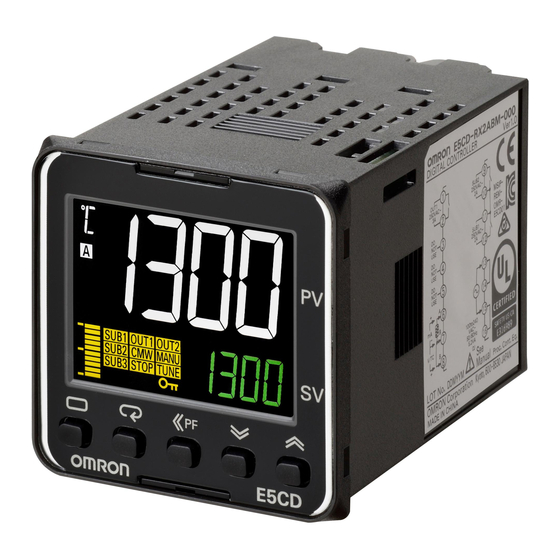
Names of Parts on Front Panel
• °C / °F : temperature unit
Operation indicators
The temperature unit is displayed when the displayed value
•
No.1 display
• SUB1: Auxiliary output 1 indicator
is a temperature. Either C or F is displayed according to
• SUB2: Auxiliary output 2 indicator
Process value or set data
the set value of the temperature unit.
type
• OUT1: Control output 1 indicator
•
Level key
Use this key to change levels:
•
TUNE:
•
No.2 display
•
Mode key
Set point, set data read-out value or
Press this key to change the contents of the display.
•
changed input valu
Press this button for 1 s or longer for reverse scroll.
e
•
Up and Down keys
• Press the O key and the M key together for at
Each press of U key increments or
least 3 seconds to switch to protect level.
advances the values displayed on the
• Shift key (PF key)
No.2 display.
The default PF Setting parameter is for shifting the digit.
Each press of D key decrements or
•
A:
This is a function key. When it is pressed, the function
returns the values displayed on the No.2
set for the PF Setting parameter will operate.
display.
Operation Menu
Operation stopped.
Input Type
Initial Setting Level
(Both control and auxiliary outputs are stopped.)
Input type
Input
Setting
Setting range
°C
°F
Platinum
0
-200 to 850
-300 to 1500
ptrn
resistance
Pt100
1
-199.9 to 500.0
-199.9 to 900.0
in-t
Program Pattern
Input Type *2
thermometer
2
0.0 to 100.0
0.0 to 210.0
off
5
3
-199.9 to 500.0
-199.9 to 900.0
M
JPt100
M
Control Period (Heating)
4
0.0 to 100.0
0.0 to 210.0
Scaling Upper Limit
cp
in-h
(Unit: Seconds)
Thermocouple
K
5
-200 to 1300
-300 to 2300
(only when setting
*Voltage output
20
6
-20.0 to 500.0
0.0 to 900.0
100
analog input)
(for driving SSR): 2
J
7
-100 to 850
-100 to 1500
M
M
Control Period (Cooling)
8
-20.0 to 400.0
0.0 to 750.0
Scaling Lower Limit
c-cp
in-l
(Unit: Seconds)
T
9
-200 to 400
-300 to 700
(only when setting
*Voltage output
20
0
analog input)
10
-199.9 to 400.0
-199.9 to 700.0
(for driving SSR): 2
E
11
-200 to 600
-300 to 1100
M
Decimal Point
M
Direct/Reverse Operation
L
12
-100 to 850
-100 to 1500
dp
(only when setting
orev
In Reverse operation
U
13
-200 to 400
-300 to 700
(Heating) =
0
analog input)
14
-199.9 to 400.0
-199.9 to 700.0
or-r
In Direct operation
M
N
15
-200 to 1300
-300 to 2300
(Cooling) =
Temperature
°C=
c
R
16
0 to 1700
0 to 3000
d-u
M
Unit
°F=
f
S
17
0 to 1700
0 to 3000
c
alt1
Alarm 1 to 4
B
18
0 to 1800
0 to 3200
M
Type
C/W
19
0 to 2300
0 to 3200
2
sl-h
PL II
20
0 to 1300
0 to 2300
SP Upper Limit
M
Infrared
10 to 70°C
21
0 to 90
0 to 190
1300
alh1
Alarm 1 to 4
Thermosensor
60 to 120°C
22
0 to 120
0 to 240
M
Hysteresis
0.2
ES1B
115 to 165°C
23
0 to 165
0 to 320
sl-l
SP Lower Limit
140 to 260°C
24
0 to 260
0 to 500
M
-200
4 to 20mA
25
Current input
ev-1
Event Input
0 to 20mA
26
Use the following ranges for scaling: -1999
M
PID•ON/OFF
Assignment 1
1 to 5V
27
to 9999, -199.9 to 999.9, -19.99 to 99.99,
cntl
msp0
In ON/OFF control =
onof
Voltage input
-1.999 to 9.999
0 to 5V
28
M
pid
In 2-PID control =
pid
0 to 10V
29
ev-2
M
Event Input
*The default is"5".
Standard or Heating/Cooling
Assignment 2
stop
s-hc
*s.err will be displayed when a platinum resistance thermometer is mistakenly connected while
Standard control =
stnd
M
input type is not set for it. To clear the s.err display, correct the wiring and cycle the power supply.
stnd
Heating and cooling control
Extraction of Square
h-c
sqr
Alarms
M
=
Root Enable
(Alarms are output from auxiliary outputs.)
(Only when analog
off
Adaptive Control
adpt
input is set)
Alarm output function
Disabled =
off
M
Alarm type
Setting
Fixed =
fix
off
Positive alarm value (X) Negative alarm value (X)
p-on
Notification =
info
M
Startup Operation
0
No alarm function
Output off
Automatic update =
auto
cont
Vary with
M
*1
1
Deviation upper/lower limit
m-pv
"L", "H" values
Model Creation
bar
PV Amplitude
Bar Display Data
X
X
0.0
mv
2
Deviation upper limit
ON
ON
M
OFF
OFF
SP
SP
M
m-mv
Model Creation
X
X
3
Deviation lower limit
ON
ON
barh
MV Amplitude
Bar Display Scaling
OFF
OFF
0.0
SP
SP
100.0
Upper Limit
L H
Vary with
M
Deviation upper/lower range
ON
*1
4
M
OFF
"L", "H" values
m-on
SP
Model Creation
ON Time
barl
Deviation upper/lower limit
L H
Vary with
Bar Display Scaling
0
*1
5
ON
Lower Limit
standby sequence ON
"L", "H" values
0.0
OFF
SP
M
X
X
M
Deviation upper limit
ON
ON
6
m-of
Model Creation
OFF
Move to Advanced
standby sequence ON
OFF
amov
SP
SP
OFF Time
0
Function Setting
X
X
Deviation lower limit
0
7
ON
ON
Level
standby sequence ON
M
OFF
OFF
SP
SP
M
X
X
8
Absolute value upper limit
ON
ON
Initial setting level enables users to specify their preferred
OFF
OFF
0
0
operating conditions (input type, alarm type, control method, etc.)
X
X
9
Absolute value lower limit
ON
ON
OFF
OFF
*2: Refer to the adjoining tables for details of input types and alarm types.
0
0
*3: Operation is stopped when moved to the initial setting level.
Absolute value upper limit
X
X
10
ON
ON
(Both control and auxiliary outputs are stopped.)
standby sequence ON
OFF
OFF
0
0
*4: The grayed-out setting items are not displayed for some models and some settings of
Absolute value lower limit
X
X
other setting items.
11
ON
ON
standby sequence ON
OFF
OFF
Typical example: The parameters are not displayed under the following conditions.
0
0
• AT Execute/Cancel: Not displayed if PID ON/OFF is set to ON/OFF.
12
LBA (only for alarm 1)
• Alarm 1 Type: The default setting is for Controllers that are not equipped with HB/HS alarms.
For a Controller equipped with HB/HS alarms, the Auxiliary Output 1 Assignment
parameter (Advanced Function Setting Level) is set to a heater alarm. If you set
13
PV Change Rate Alarm
alarm 1, the Alarm 1 Type parameter will be displayed.
X
Refer to the E5 D Digital Controllers User's Manual (Cat. No. H224) for the setting method.
X
14
SP absolute value upper limit
ON
ON
*5: The four numeric digits of the product code are displayed in the No. 2 display. The
OFF
OFF
0
0
setting cannot be changed and there is nothing that you need to set.
X
X
15
SP absolute value lower limit
ON
ON
OFF
OFF
0
0
X
X
ON
ON
16
MV absolute value upper limit
OFF
OFF
0
0
X
X
ON
17
MV absolute value lower limit
ON
OFF
OFF
Conformance to EN/IEC Standards
0
0
*1: Upper and lower limits can be set for parameters 1, 4 and 5 to provide for different
This is a class A product.
types of alarm. These are indicated by the letter "L" and "H".
• The default alarm type is "2"
In residential areas it may cause radio interference, in which case the user
may be required to take adequate measures to reduce interference.
Conformance to Safety Standard
Due to UL Listing requirements, use the E54-CT1L or E54-CT3L current
transformer with the factory wiring (internal wiring).
Use a UL category XOBA or XOBA7 current transformer that is UL Listed
for field wiring (external wiring) and not the factory wiring (internal wiring).
Always externally connect the recommended fuse that is specified in the
Instruction Manual before you use the Digital Controller.
Analog Input
• If you input an analog voltage or current, set the Input Type parameter to
the correct input type.
• Do not use the Digital Controller to measure a circuit with Measurement
Category II, III, or IV.
• Do not use the Digital Controller to measure an energized circuit to which
a voltage that exceeds 30 Vrms or 60 VDC is applied.
The protection provided by the Digital Controller may be impaired if the Digital
Controller is used in a manner that is not specified by the manufacturer.
Precautions for Safe Use
Be sure to observe the following precautions to prevent operation failure, malfunction, or adverse affects on the
performance and functions of the product. Not doing so may occasionally result in unexpected events.
Use the product within specifications.
(1) The product is designed for indoor use only. Do not use the product outdoors. Do not use or store the product
in any of the following locations.
• Places directly subject to heat radiated from heating equipment. • Places subject to intense temperature change.
• Places subject to splashing liquid or oil atmosphere.
• Places subject to icing and condensation.
• Places subject to direct sunlight.
• Places subject to vibration and large shocks.
• Places subject to dust or corrosive gas (in particular, sulfide gas and ammonia gas).
(2) Use and store the Digital Controller within the rated ambient temperature and humidity. Provide forced-cooling
if required.
(3) To allow heat to escape, do not block the area around the product. Do not block the ventilation holes on the product.
(4) Be sure to wire properly with correct signal name and polarity of terminals.
(5) Use the specified size of crimped terminals (M3, width 5.8 mm or less) for wiring. To connect bare wires to the
terminal block, use copper braided or solid wires with a gage of AWG24 to AWG18 (equal to a crosssectional
2
area of 0.205 to 0.823 mm
). (The stripping length is 6 to 8 mm.). Up to two wires of same size and type, or
two crimped terminals can be inserted into a single terminal.
(6) Do not wire the terminals which are not used.
(7) Allow as much space as possible between the controller and devices that generate a powerful high- frequency
or surge. Separate the high-voltage or large-current power lines from other lines, and avoid parallel or
common wiring with the power lines when you are wiring to the terminals.
(8) Use the Digital Controller within the rated load and power supply.
(9) Make sure that the rated voltage is attained within two seconds of turning ON the power using a switch or relay
contact. If the voltage is applied gradually, the power may not be reset or output malfunctions may occur.
(10) Make sure that the Digital Controller has 30 minutes or more to warm up after turning ON the power before
starting actual control operations to ensure the correct temperature display.
(11) When using adaptive control, turn ON power for the load at the same time as or before supplying power to the
Digital Controller.
(12) During tuning, ensure that the power for the load (e.g., heater) is ON. Otherwise, the correct tuning result
cannot be calculated and optimal control will not be possible. Tuning is used in the following functions:
AT, adaptive control, automatic filter adjustment, and water-cooling output adjustment.
(13) A switch or circuit breaker should be provided close to this unit. The switch or circuit breaker should be within
easy reach of the operator, and must be marked as a disconnecting means for this unit.
(14) Wipe off any dirt from the Digital Controller with a soft dry cloth. Never use thinners, benzine, alcohol, or any
cleaners that contain these or other organic solvents. Deformation or discoloration may occur.
(15) Design system (control panel, etc) considering the 2 second of delay that the controller's output to be set after power ON.
(16) The output will turn OFF when you move to the Initial Setting Level. Take this into consideration when performing control.
(17) The number of non-volatile memory write operations is limited. Therefore, use RAM write mode when
frequently overwriting data during communications or other operations.
(18) When disassembling the Digital Controller for disposal, use suitable tools.
(19) Do not exceed the communications distance that is given in the specifications and use the specified
communications cable. Refer to the E5 D Digital Controllers User's Manual (Cat. No. H224) for the
communications distance and cable specifications.
(20) Do not turn the power supply to the Digital Controller ON or OFF while the USB-Serial Conversion Cable is
connected. The Digital Controller may malfunction.
(21) Always turn OFF the power supply before pulling out the interior of the product, and never touch nor apply
shock to the terminals or electronic components.
When inserting the interior of the product, do not allow the electronic components to touch the case.
When you insert the interior body into the case, confirm that the hooks on the top and bottom are securely
engaged with the case.
If the terminals are corroded, replace the rear case as well.
(22) Do not use the Temperature Controller if the front sheet is peeling.
Connections
(The applicability of the electric terminals varies with the type of machine.)
Side-by-side mounting (mm)
+1.0
(48 x number of units - 2.5)
0
Control output 1
Auxiliary outputs 1and 2
Waterproofing is impossible
Relay output
with side-by-side
Relay outputs
250 VAC, 3 A
installation. When
250 VAC: 3 A
(resistive load)
(resistive load)
waterproofing is required, fit
Voltage output
watertight packing on the
(for driving SSR)
+0.6
backside of front panel.
45
12 VDC, 21 mA
0
Control Output 1
RX
QX
One relay output
One voltage output
(for driving SSR)
1
OUT1
1
+
OUT1
−
2
R
2
Q
Sensor Temperature/Analog Input
TC
Pt
I
V
A
4
4
+
4
4
−
B
mA
−
5
5
5
5
−
B
V
6
6
6
6
+
+
•
CMW: Communications writing
enabled/disabled indicator
The E5CD is set for a K thermocouple (input type of 5) by default.
Lit when communications writing is enabled
If a different sensor is used, an input error (s.err) will occur.
and not lit when it is disabled.
Check the setting of the Input Type parameter.
•
:Protection indicator
Lit when Setting Change Protect is ON
Lit during auto-tuning.
(disables the Up and Down Keys).
STOP: Control stopped indicator
*1. When complying with EMC standards, the line connecting the
•
MANU: Manual output indicator
Lit when "Run/Stop" is stopped during
sensor must be 30 m or less.
operation.
Lit when the Auto/Manual Mode is set to
If the cable length exceeds 30 m, compliance with EMC
During control stop, functions other
Manual Mode.
standards will not be possible.
than control output are valid.
*2. Use non-voltage inputs for the event inputs. The polarity for a
•
Bar Display:
non-contact input is indicated by "(-)."
Displays the MV or heater current in
Flashing or lit during adaptive control.
10 steps.
Check the wiring before turning ON the power supply.
Adjustment Level
*3
POWER ON
*5
Adjustment Level
l.adj
Displayed only once when
Operation Level
entering Adjustment Level.
M
AT Execute / Cancel
at
Process Value/Set Point
at-2
25
sktr
100%AT Execute
s.err is displayed when
off
Soak Time Remain
at-1
40%AT Execute
connected sensor is
0
0
M
different from input type.
M
M
RUN/STOP
cmwt
Hold O down
Communications Writing
r-s
When control start
Press O
a-m
Auto/Manual Switch
for at least
run
off
=
PID control only.
(less than
3 seconds
run
When control stop
M
1 second)
M
=
stop
or-r
(No.1 display flashes,
M
ct1
Heater Current 1 Value
then the control stops.)
m-sp
Multi-SP
al-1
Alarm Value
Monitor (Unit: A)
or-d
0.0
Set Point Selection
1 to 4
0
0
M
M
Hold O down
M
hb1
Heater Burnout Detection 1
sp-m
Alarm Value
(Unit: A)
*2
for at least
Set Point During
al1h
0.0
SP Ramp
Upper Limit 1 to 4
0
1 second
0
M
M
lcr1
Leakage Current 1 Value
M
ct1
Heater Current 1
Monitor (Unit: A)
al1l
Alarm Value
0.0
Value Monitor
Lower Limit 1 to 4
0.0
(Unit: A)
0
M
M
hs1
HS Alarm 1
Leakage Current 1
M
lcr1
(Unit: A)
50.0
Value Monitor
o
MV Monitor
0.0
(Unit: A)
M
(Heating)
0.0
M
sp-0
M
SP 0 to 7
prst
0
Program Start
c-o
MV Monitor
rset
(Cooling)
M
0.0
M
M
ins
PV
0.0
Input Shift
Operation level should normally be used during operations.
M
inrt
PV input
Hold O and M keys
Hold O and M keys
Slope Coefficient
1.000
down for at least
down for at least
M
1 second
3 seconds
fa
Automatic Filter
Protect Level
Adjustment
off
M
inf
Move to Protect Level
Input Digital Filter
pmov
Displayed only when a password is set.
0.0
0
Restricts moving to Protect Level.
M
a-ud
PID Update
M
Operation / Adjustment Protect
off
(Adaptive Control)
PF Key Protect
oapt
Restricts displaying and
pfpt
Restricts PF
modifying menu items in
M
Operation, Adjustment,
off
key operation.
0
w-ht
Water-cooling
and Manual Control Levels.
M
M
Output Adjustment
Parameter
off
Initial Setting / Communication Protect
pmsk
icpt
Restricts movement to the Initial
Mask Enable
M
Setting, Communications Setting,
on
Water-cooling
1
and Advanced Function Setting
w-il
M
Levels.
Proportional Band
M
prlp
Password to
1.4
Increase Threshold
Move to
Setting Change Protect
wtpt
Protect Level
M
0
Restricts changes to settings
w-dl
Water-cooling
off
M
by operating the front panel keys.
Proportional Band
M
0.6
Decrease Threshold
M
Restricts which settings can be displayed or changed, and
restricts change by key operation.
Press and hold the M Key to cycle through the parameters in reverse.
Only the value set to the ins: Temperature Input Shift parameter is applied to the entire
temperature input range. When the process value is 200°C, the process value is treated as
201.2°C after input shift if the input shift value is set to 1.2°C. The process value is treated
as 198.8°C after input shift if the input shift value is set to -1.2°C.
Error Display (troubleshooting)
Other functions
When an error has occurred, the No.1 display shows the error code. Take necessary measure
Refer to the E5 D Digital Controllers User's Manual (Cat. No. H224) for information on the
according to the error code, referring the table below.
Advanced Function Setting Level, Monitor/Setting Item Level, Manual Control Level, and other
functions.
Status at error
No.1 display
Meaning
Action
Refer to the E5 D Digital Controllers Communications Manual (Cat. No. H225) for information on
Control
Alarm
communications.
output
Check the setting of the Input Type parameter,
Operates
Input error
s.err
check the input wiring, and check for broken or
OFF
as above the
(S. Err)
*6
shorts in the temperature sensor.
upper limit.
OMRON EUROPE B.V. (Importer in EU)
After the check of input error, turn the power OFF
then back ON again. If the display remains the
Wegalaan 67-69, NL-2132 JD Hoofddorp The Netherlands
e333
A/D converter error
same, the controller must be repaired. If the
(E333)
OFF
OFF
display is restored to normal, then a probable
*6
Phone 31-2356-81-300
cause can be external noise affecting the control
FAX 31-2356-81-388
system. Check for external noise.
OMRON ELECTRONICS LLC
Turn the power OFF then back ON again. If the
display remains the same, the controller must be
2895 Greenspoint Parkway, Suite 200 Hoffman Estates, IL 60169 U.S.A.
e111
Memory error
OFF
OFF
(E111)
repaired. If the display is restored to normal, then
Phone 1-847-843-7900
a probable cause can be external noise affecting
FAX 1-847-843-7787
the control system. Check for external noise.
OMRON ASIA PACIFIC PTE. LTD.
If the input value exceeds the display limit (-9999 to 9999), though it is within the control
No. 438A Alexandra Road # 05-05/08 (Lobby 2),
range, [[[[ will be displayed under -1999 and ]]]] above 9999.
Alexandra Technopark, Singapore 119967
Under these conditions, control outputs and alarms will operate normally.
Refer to the E5 D Digital Controllers User's Manual (Cat. No. H224) for the controllable ranges.
Phone 65-6835-3011
FAX 65-6835-2711
*6: Error shown only for "Process value / Set point". Not shown for other status.
OMRON Corporation (Manufacturer)
Shiokoji Horikawa, Shimogyo-ku, Kyoto 600-8530 JAPAN
Specifications
Power supply voltage
100 to 240 VAC, 50/60 Hz or
24 VAC, 50/60 Hz / 24 VDC
E5CD
Operating voltage range
85 to 110% of the rated voltage
Power consumption
Option 000:
5.2 VA max. (100 to 240 VAC)
3.1 VA max. (24 VAC)/1.6 W max. (24 VDC)
All other specifications:
6.5 VA max. (100 to 240 VAC)
4.1 VA max. (24 VAC)/2.3 W max. (24 VDC)
Indication accuracy
Thermocouple:
(Ambient temperature: 23°C)
(±0.3 % of indication value or ±1°C,
CHN
whichever is greater) ±1 digit max.
Platinum resistance thermometer:
(±0.2 % of indication value or ±0.8°C,
E5CD
whichever is greater) ±1 digit max.
Analog input:
±0.2 % FS ±1 digit max.
Event input
Output current: approx. 7 mA per contact.
Contact input
ON:1 k
k
No-contact input
ON: residual voltage 1.5 V max.,
OFF: leakage current 0.1 mA max.
Control output 1
Relay output :SPST-NO
250VAC, 3A(resistive load)
Electrical life of relay: 100,000 operations
Voltage output (for driving SSR):
12 VDC ±20%, 21 mA
Control method
ON/OFF or 2-PID control
Auxiliary outputs
Relay outputs:SPST-NO, 250 VAC,
3 A (resistive load),
Electrical life of relay: 100,000 operations
Ambient temperature
-10 to 55°C
(Avoid freezing or condensation)
Ambient humidity
25 to 85%
©All Rights Reserved
Storage temperature
-25 to 65°C
(Avoid freezing or condensation)
Altitude
Max. 2,000m
E5 D
Recommended fuse
T2A, 250 VAC, time-lag, low-breaking capacity
Cat. No. H224
Weight
Approx. 120 g (Digital Controller only)
Degree of protection
Front panel: IP66
Rear case: IP20, Terminal section: IP00
Installation environment
Overvoltage category II, pollution
degree 2 (as per IEC61010-1)
Memory protection
Non-volatile memory
(Number of write operations: 1,000,000)
mm
(66)
Do not connect anything to the terminals that are shaded gray.
4
62
48×48
1
E5CD-
6M-
Options
Input Power Supply
Auxiliary Outputs
Control Output 1
Auxiliary Outputs
Auxiliary outputs 1 and 2
7
Auxiliary output 2
8
Cat. No. H224
1
13
7
9
Auxiliary output 1
2
14
8
10
3
15
9
E58-CIFQ2 USB
USB
4
16
10
USB
Input Power Supply
5
17
11
A
D
6
18
12
100 to 240 VAC
24 VAC/DC
11
11
°C / °F
12
12
°C °F
(no polarity)
Options
001
002
Event inputs 1 and 2,
Communications
and CT1
(RS-485) and CT1
(−)
B(+)
13
13
RS-485
1
14
14
EV1
A(−)
O
M
15
15
3
EV2
16
16
CT1
CT1
PF
17
17
PF
18
18
PF
°C
0
-200 850
Pt100
1
-199.9 500.0
2
0.0 100.0
3
-199.9 500.0
JPt100
p
Proportional
hys
4
0.0 100.0
Hysteresis (Heating)
Band
K
5
-200 1300
8.0
1.0
6
-20.0 500.0
M
M
J
7
-100 850
i
chys
Integral Time
Hysteresis (Cooling)
8
-20.0 400.0
(Unit: Seconds)
233
1.0
T
9
-200 400
M
M
10
-199.9 400.0
d
E
11
-200 600
Derivative Time
soak
(Unit: Seconds)
Soak Time
L
12
-100 850
40
1
U
13
-200 400
M
M
14
-199.9 400.0
c-p
Proportional Band
wt-b
N
15
-200 1300
Wait Band
(Cooling)
R
16
0 1700
8.0
off
S
17
0 1700
M
M
B
18
0 1800
c-i
Integral Time
(Cooling)
mv-s
C/W
19
0 2300
MV at Stop
II
233
(Unit: Seconds)
PL
20
0 1300
0.0
M
10 70°C
21
0 90
M
Derivative Time
60 120°C
22
0 120
c-d
ES1B
mv-e
(Cooling)
23
0 165
MV at PV Error
115 165°C
40
(Unit: Seconds)
0.0
24
0 260
140 260°C
M
M
4 20mA
25
sp-p
SP Response
sprt
0 20mA
26
SP Ramp Set Value
Proportional Band
1 5V
27
-199.9
999.9
-19.99
8.0
off
0 5V
28
9.999
M
M
0 10V
29
SP Response
sp-i
sprl
∗
SP Ramp Set Value
"5"
Integral Time
(SP Ramp Fall Value)
∗
233
(Unit: Seconds)
same
M
M
sp-d
SP Response
ol-h
MV Upper Limit
Derivative Time
40
(Unit: Seconds)
100.0
M
M
sp-n
ol-l
SP Response
X
MV Lower Limit
Coefficient Number
0
0.0
0
M
M
∗1
orl
1
/
d-p
Disturbance
MV Change
Proportional Band
Rate Limit
8.0
0.0
X
2
ON
M
M
OFF
SP
Disturbance
sqrp
Extraction of Square
X
d-i
3
ON
Integral Time
Root Low-cut Point
0.0
OFF
233
(Unit: Seconds)
SP
L H
M
M
∗1
/
ON
4
OFF
d-d
Disturbance
SP
w1on
Work Bits 1 to 8
Derivative Time
L H
ON Delay
∗1
ON
40
(Unit: Seconds)
5
/
ON
0
OFF
SP
M
M
X
ON
6
ON
c-db
w1of
Work Bits 1 to 8
OFF
Dead Band
OFF Delay
SP
0.0
0
X
ON
7
ON
M
OFF
SP
M
of-r
Manual Reset Value
X
Clears the offset
plcm
8
ON
Communications
50.0
during P or PD control.
OFF
Monitor
0
0
X
9
ON
M
M
OFF
0
X
ON
Adjustment level is for entering set values and shift
10
ON
OFF
0
values for control.
X
ON
11
ON
OFF
0
12
LBA
1
13
PV
X
14
SP
ON
OFF
0
X
15
SP
ON
OFF
0
X
ON
16
MV
OFF
0
X
ON
17
MV
OFF
0
∗1:
1 4 5
L H
•
"2"
1
2
3
a
UL Listing
4
b
AWG18
c
SELV
d
2
6
7
8
9
75
75
10
11
0.43 0.58 N•m
12
AT
13
14
15
16
17
18
19
20
21
mm
mm
M3
48
- 2.5
44.8×44.8
E53-COV23
Y92S-P8
Y92F-49
+0.6
45
0
E53-COV23
USB
E58-CIFQ2
夹
Y92F-58
E5 D
1 5mm
0.29
0.39N m
CMW
/
SUB1
1
SUB2
2
OUT1
1
ON
TUNE
MANU
STOP
/
"
/
"
U
10
MV
D
A
∗3
°F
-300 1500
ptrn
in-t
∗2
-199.9 900.0
off
5
0.0 210.0
M
M
-199.9 900.0
in-h
cp
0.0 210.0
-300 2300
20
100
∗
0.0 900.0
M
M
SSR
2
/
25
-100 1500
in-l
0.0 750.0
c-cp
0
s.err
0
-300 700
20
∗
M
O
-199.9 700.0
M
SSR
2
a-m
/
M
3
-300 1100
PID
dp
/
-100 1500
orev
0
M
-300 700
or-r
= or-r
-199.9 700.0
M
m-sp
SP
-300 2300
d-u
M
°C= c
= or-d
0
0 3000
°F= f
c
M
O
0 3000
M
alt1
∗2
sp-m
0 3200
1
sl-h
SP
0 3200
2
0
SP
0 2300
1300
M
M
0 190
M
alh1
ct1
1
0 240
sl-l
0.2
0 320
0.0
SP
A
0 500
-200
M
M
M
ev-1
lcr1
1
-1999 9999
cntl
PID ON/OFF
1
ON/OFF
=onof
msp0
0.0
99.99
-1.999
A
pid
2 PID
=pid
M
M
M
ev-2
prst
/
2
s-hc
stop
rset
=stnd
s.err
s.err
stnd
= h-c
M
M
M
sqr
adpt
off
off
off
fix
M
info
O M
1
M
p-on
auto
X
cont
m-pv
M
L H
PV
bar
0.0
M
mv
X
ON
m-mv
M
pmov
OFF
SP
MV
barh
X
0.0
0
ON
M
100.0
OFF
SP
m-on
M
M
L H
/
ON
barl
oapt
0
0.0
0
L H
M
M
m-of
M
/
icpt
X
OFF
amov
ON
0
OFF
SP
1
M
0
X
M
M
ON
OFF
wtpt
SP
X
off
ON
OFF
0
M
X
ON
OFF
0
X
ON
OFF
0
*2:
M
X
ON
*3:
OFF
0
*4:
・AT
/
PID ON/OFF
ON/OFF
・
X
ON
OFF
0
E5 D
(Cat. No. H224)
X
ON
OFF
*5:
0
X
ON
OFF
0
X
ON
OFF
0
EN/IEC
A
s.err
S. Err
∗6
A/D
UL
E54-CT1L E54-CT3L
e333
E333
∗6
UL
XOBA XOBA7
e111
E111
II III IV
[[[[
9999
]]]]
30Vrms 60VDC
∗6
100 240 VAC 50/60 Hz
24 VAC 50/60 Hz/24 VDC
85 110%
000:
5.2 VA 100-240 VAC
3.1 VA 24 VAC /
1.6 W 24 VDC
6.5 VA 100-240 VAC
4.1 VA 24 VAC /
2.3 W 24 VDC
23°C
±0.3%
±1°C
±1
±0.2%
±0.8°C
±1
±0.2 % FS
±1
7 mA
M3
5.8mm
AWG24
ON
1 kΩ OFF
100 kΩ
0.205 0.823mm
2
6 8mm
ON
1.5 V
OFF
0.1 mA
1
SPST-NO
250 VAC 3 A
100,000
SSR
12 VDC ±20% 21 mA
ON/OFF 2 PID
SPST-NO 250 VAC
3 A
30
100,000
-10 55°C
RH 25 85%
-25 65°C
2,000
T2A 250 VAC
2
120 g
IP66
RAM
IP20
IP00
2 IEC61010-1
E5 D
Cat. No. H224
1,000,000
USB
+1.0
0
1
1 2
E5CD- @@ @ @ 6M - @ @ @
250 VAC 3 A
250 VAC 3 A
SSR
12 VDC 21 mA
RX
QX
1
1
1 2
SSR
7
1
1
+
2
OUT1
OUT1
8
−
2
R
2
Q
1
13
7
9
1
2
14
8
10
3
15
9
/
4
16
10
5
17
11
A
D
TC
Pt
I
V
A
+
4
4
4
4
6
18
12
100 240 VAC
24 VAC/DC
−
B
mA
−
5
5
5
5
11
11
B
−
V
6
6
6
6
+
12
12
+
E5CD
K
5
s.err
001
002
/
1 2 CT1
RS-485
CT1
(−)
B(+)
13
13
RS-485
14
14
EV1
A(−)
*1.
15
15
EMC
30
EV2
30
EMC
16
16
*2.
CT1
CT1
17
17
18
18
∗5
p
l.adj
hys
8.0
1.0
M
M
M
i
chys
sktr
at
AT
/
233
1.0
100%AT
at-2
0
off
M
40%AT
at-1
M
M
M
d
soak
r-s
RUN/STOP
cmwt
O
1
40
=run
run
=stop
off
M
M
M
wt-b
M
c-p
1
ct1
al-1
8.0
off
1
1
A
M
0.0
M
0
c-i
mv-s
M
M
hb1
0.0
al1h
1
233
A
M
M
0
1
0.0
mv-e
M
c-d
M
PV
al1l
lcr1
40
0.0
1
A
M
1
0.0
M
0
sprt
M
sp-p
SP
M
hs1
SP
off
HS
1
8.0
o
MV
A
M
50.0
M
0.0
sprl
M
sp-i
SP
M
SP
SP
sp-0
same
233
c-o
SP 0
7
M
MV
0
M
0.0
ol-h
M
sp-d
MV
M
SP
100.0
ins
40
PV
M
0.0
M
ol-l
sp-n
M
MV
O M
3
SP
0.0
inrt
0
PV
M
1.000
M
orl
M
d-p
MV
0.0
fa
8.0
M
M
off
sqrp
M
d-i
Low-cut
0.0
inf
233
M
0.0
M
w1on
M
d-d
1
8
pfpt
PF
a-ud
0
40
ON
PF
PID
off
M
off
M
M
M
w1of
M
c-db
1
8
pmsk
w-ht
0
0.0
OFF
on
off
M
M
M
M
of-r
plcm
prlp
P PD
w-il
50.0
0
0
1.4
M
M
M
M
w-dl
0.6
M
ins
1.2°C
200°C
201.2°C
-1.2°C
198.8°C
E5 D
Cat. No. H224
E5 D
Cat. No. H225
OFF
(86)21-50509988
OFF
OFF
(86)21-5307-2222
OFF
OFF
-1999
9999
-1999
400-820-4535
E5 D
Cat. No. H224
http://www.fa.omron.com.cn
/
MV
MV
Advertisement

Subscribe to Our Youtube Channel
Related Manuals for Omron E5CD


Summary of Contents for Omron E5CD
- Page 1 (17) The number of non-volatile memory write operations is limited. Therefore, use RAM write mode when IP66 Degree of protection Front panel: IP66 Omron Companies shall not be responsible for conformity with any standards, codes or regulations which frequently overwriting data during communications or other operations. Safety Precautions Rear case: IP20, Terminal section: IP00...
- Page 2 携帯電話 ・ PHS ・ IP電話な ど ではご利用いただけませんので、 下記の電話番号へおかけ く だ さ い。 e111 055-982-5015 ■営業時間 : 8:00∼21:00 電話 (通話料がかかり ます) ■営業日 : 365日 [[[[ ]]]] ●FAXやWebページでもお問い合わせいただけます。 OMRON Corporation FAX 055-982-5051 / www.fa.omron.co.jp [[[[ ]]]] • • Shiokoji Horikawa, Shimogyo-ku, Kyoto 600-8530 JAPAN ●その他のお問い合わせ 納期・価格・サンプル・仕様書は貴社のお取引先、 または貴社担当オムロン販売員にご相談く ださい。 オムロン制御機器販売店やオムロン販売拠点は、 Webページでご案内しています。...
Need help?
Do you have a question about the E5CD and is the answer not in the manual?
Questions and answers