Table of Contents
Advertisement
Quick Links
Advertisement
Table of Contents

Related Manuals for IntesisBox DK-RC-MBS-1


Summary of Contents for IntesisBox DK-RC-MBS-1
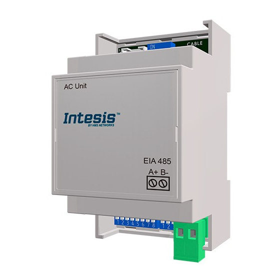
- Page 1 IntesisBox ® DK-RC-MBS-1 v.1.6 Modbus RTU (EIA-485) Interface for Daikin air conditioners. Compatible with VRV and SKY line air conditioners commercialized by Daikin. User Manual Issue Date: 12/2017 r3.3 EN Order Codes: DK-RC-MBS-1: Modbus RTU Interface for Daikin air conditioners...
- Page 2 DK-RC-MBS-1 User’s Manual r3.3 EN © Intesis Software S.L.U. 2017. All Rights Reserved. Information in this document is subject to change without notice. No part of this publication may be reproduced, stored in a retrieval system or transmitted in any form or any means electronic or mechanical, including photocopying and recording for any purpose other than the purchaser’s personal use without the written permission of Intesis Software S.L.U.
-
Page 3: Table Of Contents
DK-RC-MBS-1 User’s Manual r3.3 EN INDEX Presentation ......................4 Connection ......................5 Connect to the AC indoor unit ................5 Connection to the EIA-485 bus ................6 Quick Start Guide ....................6 Modbus Interface Specification ................7 Modbus physical layer..................7 Modbus Registers .................... -
Page 4: Presentation
Controller • DK-RC-MBS-1 Up to 63 IntesisBox devices can be installed in the same Modbus RTU bus. However, depending on the configured speed, the installation of Modbus Repeaters may be required 4/23 © Intesis Software S.L.U. - All rights reserved http://www.intesisbox.com... -
Page 5: Connection
Modbus RTU EIA-485 network. 2.1 Connect to the AC indoor unit The DK-RC-MBS-1 connects directly to the Daikin P1P2 Bus, which is not provided within the interface. Depending on which controllers are available, the recommended connection’ methods are the following ones (details in Figure 2. -
Page 6: Connection To The Eia-485 Bus
4. Connect the EIA-485 bus to the connector EIA485 of the interface. 5. Close the AC indoor unit. 6. Check the DIP-Switch configuration of the IntesisBox interface and make sure it matches the current installation’s parameters (see section 4.3). By default, the interface is set to: Modbus Slave Address ... -
Page 7: Modbus Interface Specification
4. Modbus Interface Specification 4.1 Modbus physical layer DK-RC-MBS-1 implements a Modbus RTU (Slave) interface, to be connected to an EIA-485 line. It performs 8N2 communication (8 data bits, no parity and 2 stop bit) with several available baud rates (2400 bps, 4800 bps, 9600 bps -default-, 19200 bps, 38400 bps, 57600 bps, 76800 bps and 115200 bps). - Page 8 Error Code 0: No error present ▪ 65535(-1 if it is read as signed value): Error ▪ in the communication of DK-RC-MBS-1 with the AC unit. Any other error present, see the table at the ▪ end of this document.
-
Page 9: Configuration Registers
This register allows us to provide an external temperature’s sensor from the Modbus side. Daikin indoor unit does not allow on devices like DK-RC-MBS-1 to provide directly temperature to be used as a reference of the control loop of the AC indoor unit. In order to overcome this limitation and enable the usage of an external temperature sensor (i.e.from Modbus side), DK-RC-MBS-1 applies the following mechanism (only if “external... - Page 10 24ºC in the indoor unit, it will apply a final setpoint of 24ºC + 2ºC = 26ºC). At this moment, each time that DK-RC-MBS-1 detects a change on the ambient temperature reported by the indoor unit (register 5/6), it will also change the required setpoint, in order to keep the temperature required by the user at any time.
-
Page 11: Dip-Switch Configuration Interface
(~22ºC). 4.3 DIP-switch Configuration Interface All the configuration values on DK-RC-MBS-1 can be written and read from Modbus interface. Otherwise, some of them can also be setup from its on-board DIP-switch interface. The device has DIP-switches SW1, SW3 and SW4 on the following locations:... - Page 12 DK-RC-MBS-1 User’s Manual r3.3 EN The following tables apply to the interface´s configuration through DIP-switches: SW1 – AC indoor unit’s features SW1-P1..4 Description Slave - A Daikin BRC Controller must be present in P1P2 bus, configured as Master (Default value) Master –...
- Page 13 DK-RC-MBS-1 User’s Manual r3.3 EN SW4 – Degrees/Decidegrees (x10), temperature magnitude (ºC/ºF) and EIA-485 termination resistor. SW4-P1..2-4 Description Temperature values in Modbus register are represented in degrees (x1) (Default value) Temperature values in Modbus register are represented in decidegrees (x10)
- Page 14 DK-RC-MBS-1 User’s Manual r3.3 EN SW3 – Modbus Slave address SW3-P1..6 SW3-P1..6 SW3-P1..6 SW3-P1..6 SW3-P1..6 Table 4.4 SW3: Modbus slave address 14/23 © Intesis Software S.L.U. - All rights reserved http://www.intesisbox.com This information is subject to change without notice Email info@intesisbox.com...
-
Page 15: Implemented Functions
DK-RC-MBS-1 User’s Manual r3.3 EN 4.4 Implemented Functions DK-RC-MBS-1 implements the following standard Modbus functions: 3: Read Holding Registers ▪ 4: Read Input Registers ▪ 6: Write Single Register ▪ 16: Write Multiple Registers (Despite this function is allowed, the interface does not ▪... -
Page 16: Eia-485 Bus. Termination Resistors And Fail-Safe Biasing Mechanism
This mechanism must be supplied by the Modbus Master. The DK-RC-MBS-1 device includes an on-board terminator resistor of 120Ω that can be connected to the EIA-485 bus by using DIP-switch SW4. Some Modbus RTU EIA-485 Master devices can provide also internal 120Ω terminator resistor and/or fail-safe biasing mechanism (check the technical documentation of the Master device connected to the EIA-485 network in each case). -
Page 17: Electrical And Mechanical Features
DK-RC-MBS-1 User’s Manual r3.3 EN 5. Electrical and Mechanical features Plastic, type PC (UL 94 V-0) Net dimensions (dxwxh): Operation Enclosure 0ºC to +60ºC 93 x 53 x 58 mm / 3.7” x 2.1” x 2.3” Temperature Color: Light Grey. RAL 7035... -
Page 18: List Of Supported Ac Unit Types
DK-RC-MBS-1 User’s Manual r3.3 EN 6. List of supported AC Unit Types. A list of Daikin indoor unit model’s references compatible with DK-RC-MBS-1 and its available features can be found on this link: https://www.intesisbox.com/intesis/support/compatibilities/IntesisBox_DK-RC-xxx-1_AC_Compatibility.pdf 18/23 © Intesis Software S.L.U. - All rights reserved http://www.intesisbox.com... -
Page 19: Error Codes
Error Remote Error Description Modbus category Controller DK-RC-MBS-1 No active error External protection devices activated Indoor unit PCB assembly failure Interlock error for fan Drain level system error Temperature of heat exchanger (1) error Temperature of heat exchanger (2) error... - Page 20 DK-RC-MBS-1 User’s Manual r3.3 EN Compressor motor over current sensor is abnormal Overload or over current sensor of fan motor is abnormal Sensor system of over-current of AC input Outdoor air thermistor system error Discharge air thermistor system error Pump motor sensor system of over current is abnormal...
- Page 21 DK-RC-MBS-1 User’s Manual r3.3 EN Capacity setting error (outdoor) Low pressure drop due to insufficient refrigerant or electronic expansion valve error, etc. Reverse phase, Open phase Power voltage failure / Instantaneous power failure System Failure to carry out check operation, transmission error...
- Page 22 Centralized remote control devices inappropriate combination Centralized remote controller address setting error 65535 Error in the communication of DK-RC-MBS-1 with the DK-RC-MBS-1 (-1) AC unit In case to detect an error code not listed, contact your closest Daikin technical support service.
-
Page 23: Annex 1: Master/Slave Of Operation Mode
Remote Controller of Daikin. The unit which controls the Operation mode must have installed a Remote Controller. When a DK-RC-MBS-1 is configured as Master of Mode via the Remote Controller of its indoor unit, it can control all the modes of the system. The Mode selection of the gateways remaining and remote controllers installed in the indoor units remaining is going to be affected by the one chosen as Master of Mode.
Need help?
Do you have a question about the DK-RC-MBS-1 and is the answer not in the manual?
Questions and answers