Table of Contents
Advertisement
THE FOLLOWING SERVICING INSTRUCTIONS ARE
FOR USE BY QUALIFIED PERSONNEL ONLY. TO
AVOID PERSONAL INJURY, DO NOT PERFORM ANY
SERVICING OTHER THAN THAT CONTAINED IN
OPERATING
QUALIFIED TO DO SO. REFER TO THE OPERATORS
Safety SUMMARY AND THE SERVICE SAFETY
SUMMARY PRIOR TO PERFORMING ANY SERVICE.
Tektronix, Inc.
P.O. Box 500
Beaverton, Oregon
070-4204-00
Product Group 46
WARNING
INSTRUCTIONS
PLEASE CHECK FOR CHANGE INFORMATION
AT THE REAR OF THIS MANUAL.
INSTRUCTION
97077
Tektronix
COMMITTED TO EXCELLENCE
UNLESS
2236
Serial Number
YOU
ARE
MANUAL
First Printing MAR 1983
Revised NOV 1986
Advertisement
Table of Contents
Troubleshooting

Subscribe to Our Youtube Channel
Related Manuals for Tektronix 2236


Summary of Contents for Tektronix 2236
- Page 1 UNLESS QUALIFIED TO DO SO. REFER TO THE OPERATORS SAFETY SUMMARY AND THE SERVICE SAFETY SUMMARY PRIOR TO PERFORMING ANY SERVICE. PLEASE CHECK FOR CHANGE INFORMATION AT THE REAR OF THIS MANUAL. 2236 OSCILLOSCOPE SERVICE INSTRUCTION MANUAL Tektronix, Inc. P.O. Box 500...
- Page 2 Copyright © 1983 Tektronix, Inc. All rights reserved. Contents of this publication may not be reproduced in any form without the written permission of Tektronix, Inc. Products of Tektronix, Inc. and its subsidiaries are covered by U.S. and foreign patents and/or pending patents. TEKTRONIX, TEK, SCOPE-MOBILE, and registered trademarks of Tektronix, Inc.
-
Page 3: Table Of Contents
2236 Service TABLE OF CONTENTS Page Page LIST OF ILLUSTRATIONS ........SECTION 3 THEORY OF OPERATION LIST OF TABLES ............. INTRODUCTION ......OPERATORS SAFETY SUMMMARY ...... SECTION ORGANIZATION ..SERVICING SAFETY SUMMARY......INTEGRATED CIRCUIT DESCRIPTIONS ......GENERAL DESCRIPTION ....SECTION 1 SPECIFICATION OSCILLOSCOPE ...... -
Page 4: Table Of Contents
2236 Service TABLE OF CONTENTS (cont) Page Page SECTION 3 THEORY OF OPERATION (cont) THEORY OF OPERATION (cont) SECTION 3 HORIZONTAL ......3-14 SCOPE SWEEP SYSTEM Horizontal Preamplifier ..3-14 3-28 INTERFACE ......3-15 X-Y Amplifier ...... - Page 5 2236 Service TABLE OF CONTENTS (cont) Page Page SECTION 5 ADJUSTMENT PROCEDURE SECTION 6 MAINTENANCE (cont) INTRODUCTION ......OBTAINING REPLACEMENT PURPOSE ........PARTS ........6-22 STRUCTURE ......MAINTENANCE AIDS ....6-22 TEST EQUIPMENT ....INTERCONNECTIONS ....6-22 LIMITS AND TOLERANCES ..
-
Page 6: Table Of Contents
Typical waveforms for the Delta Time func- 3-13 OR Y.and EXT INPUT connectors .... 1-17 tion with Valt HI ........3-31 Physical dimensions of the 2236 Oscillo- 3-14 Typical waveforms for the Delta Time func- scope ............1-18 tion with Valt L O ........ -
Page 7: Table Of Contents
2236 Service LIST OF TABLES Page Page Table Table Deflection Accuracy Limits ...... . 5-9 Electrical Characteristics......1-2 Settings for Bandwidth Checks ....5-12 Environmental Characteristics..... 1-16 Settings for Timing Accuracy Checks ..5-17 Physical Characteristics ...... - Page 8 2236 Service OPERATORS SAFETY SUMMARY The general safety information in this part of the summary is for tooth operating and servicing personnel. Specific warnings and cautions will be found throughout the manual where they apply and do not appear in this summary.
- Page 9 2236 Service SERVICING SAFETY SUMMARY FOR QUALIFIED SERVICE PERSONNEL ONLY Refer also to the preceding Operators Safety Summary. Disconnect power before removing protective panels, sol Do Not Service Alone dering, or replacing components. Do not perform internal service or adjustment of this prod...
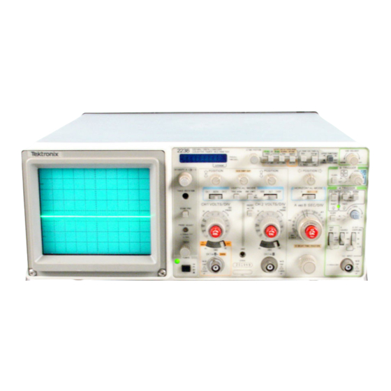
- Page 10 2236 Service The 2236 Oscilloscope. viii...
-
Page 11: Introduction
A and B SEC/DIV switch is set to 0.05 ns. PERFORMANCE CONDITIONS The following electrical characteristics (Table 1-1) are valid for the 2236 when it has been adjusted at an ambient The Counter Timer section of the CTM measures fre temperature between +18°C and +28°C, has had a warm... - Page 12 Specification— 2236 Service Table 1-1 Electrical Characteristics Performance Requirements Supplemental Information Characteristics VERTICAL DEFLECTION SYSTEM 5 mV per division to 5 V per division Deflection Factor gain is adjusted with VOLTS/DIV switch 2 mV per division to 5 V per division set to 10 mV per division.
- Page 13 Specification— 2236 Service Table 1-1 (cont) Performance Requirements Supplemental Information Characteristics VERTICAL DEFLECTION SYSTEM (cont) Bandwidth (cont) 10 Hz or less at —3 dB.a AC Coupled Lower Limit Upper limits (—3 dB) bandpass at Bandwidth Limiter 20 MHz ±10%. 500 kHz ±30%.®...
- Page 14 Specification— 2236 Service Table 1-1 (cont) Characteristics Performance Requirements Supplemental Information TRIGGER SYSTEM A TRIGGER Sensitivity External trigger signal from a 50 0 source driving a 50 0 coaxial cable P-P AUTO and NORM Modes terminated in 50 0 at the input connector.
- Page 15 Specification— 2236 Service Table 1-1 (cont) Characteristics Supplemental Information Performance Requirements TRIGGER SYSTEM (cont) LEVEL Control Range (cont) Trigger View System Deflection Factor Internal Same as vertical. External 100 mV per division. AC and DC DC ± 10 1 V per division.
- Page 16 Specification— 2236 Service Table 1-1 (cont) Characteristics Supplemental Information Performance Requirements HORIZONTAL DEFLECTION SYSTEM >nt) (C< Sweep Length Greater than 10 division. A/B SWP SEP Range ± 3.5 divisions or greater. Delay Time Applies to 0.5 its per division and slower Dial Control Range <0.5 +300 ns to >...
- Page 17 Specification— 2236 Service Table 1-1 (cont) Supplemental Information Characteristics Performance Requirements COUNTER-TIMER Frequency Ranges Maximum Resolution® 100 Hz 0.00001 Hz 1 kHz 0.0001 Hz 10 kHz 0.001 Hz 100 kHz 0.01 Hz 1 MHz 0.1 Hz 10 MHz 1 Hz...
- Page 18 Specification— 2236 Service Table 1-1 (cont) Supplemental Information Characteristics Performance Requirements COUNTER-TIMER (cont) Period Ranges Maximum Resolution* 1 M S 100 ns 100 ms 10ns 10 ms 1 ns 1 ms 100 ps 10 ps Minimum Input Period See trigger specifications.
- Page 19 Specification— 2236 Service Table 1-1 (cont) Characteristics Performance Requirements Supplemental Information COUNTER-TIMER (cont) Width (cont) Minimum Input Width 5 ns.a Maximum Displayable Width 5 seconds.3 Nongated Mode (seconds) Resolution Error ± - 4 - (TJE of leading edge L v N 10 nslac ±...
- Page 20 Specification— 2236 Service Table 1-1 (cont) Characteristics Performance Requirements Supplemental Information COUNTER-TIMER (cont) Delay Time (cont) Minimum Displayable Delay 500 ns.a Time Maximum Displayable Delay 2.5 seconds.3 Time B Triggered After Delay (seconds) ± —7 — (TJE of leading edge ±TJE...
- Page 21 Specification— 2236 Service Table 1-1 (cont) Characteristics Supplemental Information Performance Requirements COUNTER-TIMER (cont) Delta Time (cont) B Runs After Delay (cont) B Triggered After Delay With VERTICAL MODE Switch in CH 1, CH 2, ADD, and CHOP (seconds) Resolution Error ±...
- Page 22 Specification— 2236 Service Table 1-1 (cont) Performance Requirements Supplemental Information Characteristics MULTIMETER (cont) DC Volts (cont) Accuracy ±(0.1% of reading + 1 LSD). + 18°C to +28°C ±(0.2% of reading + 4 LSDs).a 0°C to +18°C and +28°C to +40°C.
- Page 23 Specification— 2236 Service Table 1-1 (cont) Performance Requirements Supplemental Information Characteristics MULTIMETER (cont) Resistance (cont) Diode Detection (Fully Automatic) 0.15 volts to 2.0 volts.3 Detectable Forward Voltage Drop Resistance shunts detectable device. Minimum Shunt Resistance >2000 0 per volt of forward drop.3...
- Page 24 Specification— 2236 Service Table 1-1 (cont) Performance Reqi irements Characteristics Supplemental Information MULTIMETER cont) Multimeter Inputs Isolated from the oscillosc ape ground.® In all CTM functions and ranges. Input Impedance Resistance (DCV) 10 Mfi ±0.25%.a Capacitance (AC RMSV) 180 pF ±10%.a...
- Page 25 Specification— 2236 Service Table 1-1 (cont) Supplemental Information Performance Requirements Characteristics MULTIMETER (cont) CH 1 Volts (cont) Selected by setting the Channel 1 input AC RMS Volts coupling switch to AC RMSV. Display Update Rate s>2.5 per second. P6121 10X Probe...
- Page 26 Specification— 2236 Service Table 1-2 Environmental Characteristics Characteristics Description NOTE The instrument meets the requirements of MIL-T-28800C, paragraphs 4.5.5.1.3, 4.5.5.1.4, and 4.5.5.1.2.2 for Type III, Class 5 equipment, except for maximum operating temperature, and minimum storage temperature as indicated. Temperature Operating 0°...
- Page 27 Specification— 2236 Service Table 1-3 Physical Characteristics Description Characteristics Weight With Power Cord With Cover, Probes, and Pouch 7.3 kg (16 lb). Without Cover, Probes, and Pouch 6.0 kg (13.3 lb). Domestic Shipping Weight 10.1 kg (22.2 lb). 137 mm (5.4 in).
- Page 28 Specification— 2236 Service Figure 1-2. Physical dimensions of the 2236 Oscilloscope. ADD JAN 1985 1-18...
-
Page 29: Safety
1 2 0 V N E M A S -1 5 -P 1 2 0 V / considerations pertaining to the use of the 2236. Before IEC 8 3 1 5 A connecting the instrument to a power source, carefully read Universal the following about line voltages, power cords, and fuses. -
Page 30: Instrument Cooling
Operating Instructions— 2236 Service INSTRUMENT COOLING Always maintain adequate instrument cooling. The venti LINE lation holes on both sides of the equipment cabinet and the FUSE fan-exhaust holes in the rear panel must remain free of obstruction. POWER CORD 4205-02 Fig. -
Page 31: Vertical
Operating Instructions— 2236 Service 4205-03 Fig. 2-3. Power and display controls and indicators and PROBE ADJUST output. ( I T ) A and B INTENSITY Controls— Determine the bright ness of the A and B Sweep traces. VERTICAL Refer to Figure 2-4 for location of items 9 through 17. -
Page 32: Horizontal
Operating Instructions— 2236 Service settings of the VOLTS/DIV switches. In CH 1 V mode, CH 2— Selects only the Channel 2 input signal for the CH 1 VOLTS/DIV Variable control has no influ display. ence on the Channel 1 volts measurements. - Page 33 Operating Instructions— 2236 Service Fig. 2-5. Horizontal controls. 1-2-5 sequence. To obtain calibrated sweep speeds, SEC/DIV Variable knob to regain the XI sweep the A and B SEC/DIV Variable control must be in the speed. calibrated detent (fully clockwise). A SEC/DIV—The calibrated sweep speed is ( 2 n HORIZONTAL MODE Switch—Three-position switch...
-
Page 34: Trigger
Operating Instructions— 2236 Service the B SEC/DIV switch setting. The start of the B Sweep is delayed from the start of the A Sweep by a time determined by the settings of both the A SEC/DIV switch and the B DELAY TIME POSI... -
Page 35: Vert Mode Trigger Source
Operating Instructions— 2236 Service ( 2? ) Table 2-1 A TRIGGER LEVEL Control— Selects the amplitude point on the trigger signal at which the sweep is VERT MODE Trigger Source triggered. VERTICAL MODE Trigger Source (2 8 J SLOPE Switches— Select the slope of the signal that CH 1 CH 1 OR X &... -
Page 36: Counter, Timer, And Multimeter
Operating Instructions— 2236 Service WIDTH— Measures the width of the trigger signal COUNTER,TIMER, AND MULTIMETER from the output of the A Trigger circuit (instrument in A HORIZONTAL MODE) or the B Trigger circuit Refer to Figure 2-7 for location of items 35 through 38. -
Page 37: Right Side Panel
Operating Instructions— 2236 Service CH 1 V— Measures dc voltage or true ac rms volt press in any of the CTM front panel buttons to re age signals applied to the CH 1 OR X & DMM verti gain normal measurement mode. Repeated press... -
Page 38: Multimeter Right Side Panel Connectors
Operating Instructions— 2236 Service Fig. 2-9. Rear-panel connector. Fig. 2-8. Multimeter right side panel connectors. 2-10... -
Page 39: Operating Considerations
GROUNDING The most reliable signal measurements are made when the 2236 and the unit under test are connected by a common reference (ground lead), in addition to the signal CENTER RISE AN D lead or probe. -
Page 40: Power-Up Checks
If the noise is of sufficient amplitude, it can result in inaccurate, measurements due to false trig gering. The 2236 has a 20 MHz Bandwidth Limiter that is POWER-UP CHECKS helpful in removing or reducing the noise in the A and B Trigger systems. - Page 41 Operating Instructions— 2236 Service no b trig—When either the A TIME or DLY TIME “ProbE-?” to indicate that the temperature probe is mode and either ALT or B HORIZONTAL MODE is either faulty or disconnected from the Multimeter input selected with the A Sweep triggered and the B Trigger connectors.
-
Page 42: Operator's Adjustments
Operating Instructions— 2236 Service OPERATOR’S ADJUSTMENTS INTRODUCTION A TRIGGER NORM VAR HOLDOFF To verify the operation and accuracy of your instrument P-P AUTO Mode before making measurements, perform the following SLOPE adjustment procedures. Adjustments beyond the scope of LEVEL Midrange “Operator’s... -
Page 43: Probe Compensation
Operating Instructions— 2236 Service PROBE COMPENSATION Channel 1 and Channel 2 CO RR EC T (FLAT) Misadjustment of probe compensation is one of the source of measurement error. Most attenuator probes are equipped with a compensation adjustment. To ensure opti... -
Page 44: Equipment Required For 10X Probe
Operating Instructions— 2236 Service Table 2-3 Adjust the generator output to produce a 400 mV, 10 Equipment Required for 10X Probe Compensation kHz display. Vertically center the display. Description Minimum Specification Set UPPER FUNCTIONS-LOWER FUNCTIONS switch to OUT and press in the CH 1 V button. -
Page 45: Theory Of Operation Introduction
Section 3— 2236 Service THEORY OF OPERATION INTRODUCTION SECTION ORGANIZATION INTEGRATED CIRCUIT DESCRIPTIONS Digital Logic Conventions This section of the manual contains a general summary of instrument functions followed by a detailed description of Digital logic circuits perform many functions within the each major circuit. -
Page 46: General Description
B trace with respect to the A trace when Alt Hori zontal Mode is selected. When reading this general circuit description of the 2236 Oscilloscope, refer to the block diagrams (Fig ures 9-4 through 9-7) located in the “Diagrams" sec The A Trigger circuitry uses either an Internal Trigger sig... - Page 47 Horizontal mode displays and includes the B Miller Sweep Generator and B Sweep Logic circuitry. In addition to pro The CTM (Counter-Timer-Multimeter) section of the 2236 viding the B Sweep sawtooth waveform, signals are gener Oscilloscope utilizes input signals from the three front-panel...
-
Page 48: Detailed Circuit Description
OSCILLOSCOPE The oscilloscope part of the 2236 Oscilloscope functions as a conventional oscilloscope. In addition, signals are produced by the circuitry for use by the CTM when making front-panel voltage and timing measurements. -
Page 49: Buffer Amplifier And Gain Switching Network
Theory of Operation— 2236 Service A probe coding ring on the CH 1 OR X & DMM input the circuitry is switching that provides extra gain for the 2 connector is used by the CTM Probe Decoder circuit. See mV position of the VOLTS/DIV switch, adjustments for am... -
Page 50: Channel Switch And Vertical Output
Theory of Operation— 2236 Service When TRIG VIEW push button S200 is pressed in, -8.6 V Common-base transistors Q102 and Q103 convert dif is applied to R138 and R188 to turn off the transistors in ferential current from the Paraphase Amplifier into level- U130 and U180 with ungrounded collectors. -
Page 51: Delay Line Driver
Theory of Operation— 2236 Service CHANNEL1 DISPLAY ONLY. The CH ^position of S550 from U537B will be LO. Input signals to U537A will be the HI grounds the S input of U540A while the R input is held HI from U537C and the Alt Sync signal from the Holdoff cir... -
Page 52: A/B Sweep Separation Circuit
Theory of Operation— 2236 Service BEAM FIND switch S390 adjusts output-amplifier bias drive one input transistor in U310, and the collectors of the ing to limit the voltage swing at the crt plates. This keeps U310 input transistors in turn supply emitter current to two the vertical trace within the graticule area for locating off... -
Page 53: Internal Trigger Amplifier
Theory of Operation— 2236 Service A External Trigger Amplifier When Channel 1 is selected (VERTICAL MODE switch set to CH 1), the input to U565C will be HI. The gate output The A External Trigger Amplifier buffers signals applied will be LO and the Channel 1 signal will be selected. The LO to the EXT INPUT connector to drive the A Trigger Genera... -
Page 54: A Trigger Level Comparator
Theory of Operation— 2236 Service current mirror that converts the differential output to a sin In the P-P Auto and TV Field modes, Q413 is off and CR414 and CR415 are reverse biased. Trigger signals se gle-ended current to drive amplifier U480C. Slope Balance lected by the A SOURCE switch are applied to peak detec... -
Page 55: A Miller Sweep Generator
Theory of Operation— 2236 Service Figure 3-3. Block diagram of the A Sweep Generator and Logic circuitry. A Miller Sweep Generator When the output reaches approximately 12 V, the Sweep Logic circuitry will initiate the holdoff period in which Q701 is The A Miller Sweep Generator produces a linear voltage turned on and the A Sweep Generator is reset. -
Page 56: B Miller Sweep Generator
Theory of Operation— 2236 Service SGL SWP. In the Sgl Swp Mode, both the P-P AUTO DS518. The output state of U502 is used in the Auto Base and NORM buttons are out. This results in a LO at the out... -
Page 57: B Trigger Level Comparator
Theory of Operation— 2236 Service The inputs to the comparator, U655, are the Delay signal B Trigger Level Comparator (SN B014886 & UP) from the Analog Section of the Delay/Delta Time Controller The B Trigger Level Comparator is composed of transis... -
Page 58: Alternate Display Switching Logic
Theory of Operation— 2236 Service functions as described above. When the output of U660F INTENSITY controls determine the intensity of the A and B goes HI, U670A is no longer held reset and the first B trigger Sweeps. The B Gate signal is applied through R679 to the... -
Page 59: X-Y Amplifier
Theory of Operation— 2236 Service When the X-Y mode is selected, Q737 is biased on to The A and B Sweeps are applied to the emitters of establish a HI on U760 pin 12 so that the A and B Sweeps Q732 and Q742, through Sweep Gain potentiometers are disconnected from the Preamplifier outputs. -
Page 60: Z-Axis Amplifier
Theory of Operation— 2236 Service The base voltages of Q770 and Q780 are at nearly the same External Z-Axis input voltages establish proportional in dc level due to forward-biased diodes CR765 and CR768 put currents through R822 and R823, and Amplifier sensitiv... -
Page 61: Dc Restorer
Theory of Operation— 2236 Service Dc Restorer The Dc Restorer is referenced to the -2 -k V crt cathode voltage through R858 and CR854. Initially, both C855 and The Dc Restorer circuit produces the crt control-grid bias C854 will charge up to a level determined by the difference and couples both dc and ac components of the Z-Axis Am... -
Page 62: Power Supply And Probe Adjust
Theory of Operation— 2236 Service During periods that C854 is charging, the crt control-grid emitter of Q928 and by the voltage divider consisting of voltage is held constant by the long time-constant discharge R925 and R927. The zener diode will keep Q928 off until the path of C855 through R860. -
Page 63: Inverter
Theory of Operation— 2236 Service R938, and R939. The error amplifier, composed of Q938 Once the supply is running, power to U930 will be sup and Q939, is a differential amplifier that compares the refer plied from the winding connected to pins 6 and 7 of T906. -
Page 64: Probe Adjust
-0 .5 V. The CTM (Counter-Timer-Multimeter) circuitry of the 2236 Oscilloscope utilizes input signals from the three front-panel BNC connectors, the DMM leads, or the temperature probe to calculate and display CTM parameter results. Measurements that are a function of time use additional control signals from the oscilloscope. -
Page 65: Buffered Data Bus Latch
Theory of Operation— 2236 Service Buffered Data Bus Latch Display and Filament Driver The Buffered Data Bus Latch, U1409, is an 8-bit trans The display panel V9900 is a vacuum-fluorescent type parent latch used to buffer data from the CPU that is being and functions like a crt. -
Page 66: Time Counter Read Ports
Theory of Operation— 2236 Service Time Counter Read Ports quad flip-flop, and is clocked by the Dmmlink control line. Resistors R1521, R1522, and R1523 perform a TTL-to-ECL The Time Counter Read Ports, composed of U1203, level conversion of the least-significant output bit of the... -
Page 67: Synchronizer
Theory of Operation— 2236 Service Synchronizer CR1001 to cause the gate to function as a noninverting buffer. The output of the Input Multiplexer drives the clock The Synchronizer circuitry is used for gating signals from input of U1001A, and since Q1012 is biased on by U1006A, the Input Multiplexer and the 100 MHz reference clock to it also drives one input of U1003B. -
Page 68: Typical Waveforms For The Nongated Period
Theory of Operation— 2236 Service place a LO on pin 5 of U1004A. The output of U1004A will NONGATED WIDTH. In this mode, the Width signal is HI, which results in Q1012 being biased off and Q1011 being therefore be the Delay End signal and will be applied to pin biased on. -
Page 69: Typical Waveforms For The Gated Period
Theory of Operation—2236 Service Figure 3-8. Typical waveforms for the Gated Period function. U1003B U1002B INPUT SIGNAL ENABLE ENABLE 4204-26 Figure 3-9. Simplified diagram of the Width measurement circuitry. 3-25... - Page 70 Theory of Operation— 2236 Service ENABLE INPUT SIGNAL n n n p r 100MHz j u U ■ ■ u ' U U1001A t a -q U10 01B-D U1001B-Q ____ i u 1 _ ___ ____ i u L 4 2 0 4 - 2 7 Figure 3-10.
-
Page 71: Oscillators
100-MHz output. Oscillators The 2236 is equipped with either the standard crystal FREQUENCY DIVIDER. The frequency divider consists oscillator or an optional temperature-compensated crystal of U1302, U1303B, Q1301, and Q1302. Bi-quinary counter oscillator. -
Page 72: Scope Sweep System Interface
Theory of Operation— 2236 Service shift the reset signal to reset U1103, and CR1100 is used to The Q output of U1602B is applied to the circuit consist ing of R1609, Cl 600, R1607, and R1608, which converts reset U1100. -
Page 73: Delay/Delta Time Controller Analog Section
Theory of Operation— 2236 Service Intensified Zone Controller gate an interval only when pin 14 of U1002C is HI. This is the shorter of the two delay periods. When the firmware Controller 1C U1603 selects the proper signal for control... - Page 74 Theory of Operation— 2236 Service 3-30...
-
Page 75: Typical Waveforms For The Delta Time Func Tion With Valt Hi
Theory of Operation—2236 Service Figure 3-13. Typical waveforms for the Delta Time function with Valt HI. 3-31... -
Page 76: Input Switching Network
Theory of Operation— 2236 Service high-impedance input. If the input voltage is ac, an rms ac Input Switching Network converter is used to produce a corresponding dc-output Input signals to the DMM are selected and conditioned voltage. by the Input Switching Network. The position of the UPPER... -
Page 77: Input Filter
Theory of Operation— 2236 Service when one end each of Cl 807 and Cl 808 are grounded. Ac compensation of the divider network is provided by C l827. See the “Ac Compensation” section for circuit Switch leakage is prevented by guarding RT1806. -
Page 78: Rms Converter
Theory of Operation— 2236 Service With pin 6 of U1803 at ground potential, there is nomi divider compensation upon which the effective capacitance nally no offset voltage supplied to U1802 and no current changes of Cl 827 are added. flows through R1813. Should an offset develop, current will flow through R1813 and Cl 811 to either charge or dis... -
Page 79: Ohms Reference
Theory of Operation— 2236 Service Input signals to the V/F Converter from the Multiplexer age at that pin is established by the divider network are applied to unity-gain buffer U1900D. The divider at the composed of R1931 and R1932. The voltage to this divider... -
Page 80: Overload Protection
Theory of Operation— 2236 Service When a DMM control word is received which enables Thermistor RT1915 heats due to the power it is dissipat U1904, U1907B and U1907C switch at a 400 Hz rate and ing until it reaches 80 °C. Its resistance then rises dramati... -
Page 81: Dmm Power Supply
Theory of Operation— 2236 Service DMM Power Supply full-wave rectified by the bridge composed of CR1801, CR1802, CR1803, and CR1804, and capacitors Cl 903 and The DMM power supply provides supply voltages while Cl 904 provide filtering for the +12-V and -1 2 -V supplies maintaining circuit isolation from chassis ground. -
Page 82: Purpose
Section 4— 2236 Service PERFORMANCE CHECK PROCEDURE INTRODUCTION TEST EQUIPMENT PURPOSE The “Performance Check Procedure" is used to verify the The test equipment listed in Table 4-1 is a complete list of the equipment required to accomplish both the “Perfor... -
Page 83: Preparation For Checks
Performance Check Procedure— 2236 Service PREPARATION FOR CHECKS Before performing any procedure in this section, set the POWER switch to ON and allow a 30-minute warm-up period. It is not necessary to remove the instrument cover to accomplish any subsection in the “Performance Check Pro... - Page 84 Performance Check Procedure— 2236 Service Table 4-1 (cont) Item No. and Examples of Suitable Purpose Description Minimum Specification Test Equipment Signal termination. 9. Termination Impedance: 50 0. Connectors: BNC. Tektronix Part Number 011-0049-01. (2 required) Tektronix Part Number 067-0525-02. 10. Dual-Input...
-
Page 85: Index To Performance Check Steps
Performance Check Procedure— 2236 Service INDEX TO PERFORMANCE CHECK STEPS Trigger 1. Check Internal Triggering ........4-12 2. Check External Triggering ........ 4-13 Vertical 3. Check External Trigger Ranges ......4-14 4. Check Single Sweep Operation ......4-14 1. Check Deflection Accuracy and Variable Range 2. - Page 86 Performance Check Procedure— 2236 Service VERTICAL Equipment Required (see Table 4-1): Dual-Input Coupler (Item 10) Calibration Generator (Item 1) Leveled Sine-Wave Generator (Item 2) 10X Attenuator (Item 11) BNC T-Connector (Item 12) Two 50-fi BNC Cables (Item 8) 10X Probe (provided with instrument)
- Page 87 Performance Check Procedure— 2236 Service c. Adjust the CH 2 VOLTS/DIV Variable control to pro j. Set the A EXT COUPLING switch to DC -= - 10. duce a 4.4-division display. Set the CH 2 VOLTS/DIV switch to 10 mV.
-
Page 88: Settings For Bandwidth Checks
Performance Check Procedure— 2236 Service j. Connect the cable to the CH 2 OR Y input connector 6. Check Bandwidth Limit Operation and set the VERTICAL MODE switch to CH 2. a. Set: BW LIMIT On (button in) k. Repeat parts c through h using the Channel 2... - Page 89 Performance Check Procedure— 2236 Service i. Set the generator to produce a 50-kHz, 6-division g. Set: display. VERTICAL MODE CH 1 Channel 1 Input Coupling Channel 2 Input Coupling j. Set the VERTICAL MODE switch to BOTH. h. CHECK— Display amplitude is 0.05 division or less.
- Page 90 Performance Check Procedure— 2236 Service HORIZONTAL Equipment Required (see Table 4-1): 50-fl BNC Cable (Item 8) Calibration Generator (Item 1) 50-fl BNC Termination (Item 9) Leveled Sine-Wave Generator (Item 2) Time-Mark Generator (Item 3) Select 50-ns time markers from the time-mark INITIAL CONTROL SETTINGS generator.
- Page 91 Performance Check Procedure— 2236 Service 2. Check Variable Range and Sweep Separation Table 4-4 Settings for Timing Accuracy Checks a. Set: HORIZONTAL MODE SEC/DIV Time-Mark Generator Setting A and B SEC/DIV 0.2 ms Switch Setting Normal X10 Magnified SEC/DIV Variable...
- Page 92 Performance Check Procedure— 2236 Service Select 10- time markers from the time-mark Connect the standard-amplitude generator output via generator. a 50-0 cable to the CH 1 OR X input connector. CHECK— Start of the sweep can be positioned to the Set the generator to produce a 50-mV signal.
- Page 93 Performance Check Procedure— 2236 Service TRIGGER Equipment Required (see Table 4-1): 50-0 BNC Termination (Item 9) Leveled Sine-Wave Generator (Item 2) 50-0 BNC Cable (Item 8) INITIAL CONTROL SETTINGS c. Set the generator to produce a 10-MHz, 3.5-division display. Vertical (Both Channels) d.
- Page 94 Performance Check Procedure— 2236 Service aa. Repeat parts i through k. k. CHECK—The readout is stable and accurately dis plays the input signal frequency. ab. Move the cable from the CH 1 OR X input connector to the CH 2 OR Y input connector. Set the VERTICAL .
- Page 95 Performance Check Procedure— 2236 Service l. Repeat parts c and d. g. CHECK— Display is triggered along the entire nega tive slope of the waveform as the A TRIGGER LEVEL con trol is rotated. m. Increase the generator output voltage to 300 mV.
- Page 96 Performance Check Procedure— 2236 Service Equipment Required (see Table 4-1): Adapter (Item 15) Pulse Generator (Item 4) Dc and Ohms Calibrator (Item 5) Adapter (Item 16) Ac Calibration System (Item 6) Resistor (Item 17) WWV Receiver (Item 7) Resistor (Item 18)
- Page 97 Performance Check Procedure— 2236 Service 3. Check Width g. Set the A and B SEC/DIV switches to 0.5 a. Set: h. Align the start of the A Sweep with the 1st vertical HORIZONTAL MODE graticule line using the Horizontal POSITION control.
- Page 98 Performance Check Procedure— 2236 Service c. Disconnect the test equipment from the instrument. CHECK— Reading is between .99949 ns and 1.00051 8. Check Ac Volts Zero f. Disconnect the test equipment from the instrument. a. Select the AC RMSV function.
- Page 99 Performance Check Procedure— 2236 Service b. Connect the ac volts calibrator via a female-to-dual e. CHECK— Reading is between -.0 0 1 2 V and .0012 V. banana adapter and a 50-0 cable to the CH 1 OR X & DMM input connector.
- Page 100 Performance Check Procedure—2236 Service NOTE 12. Check Ohms The next two checks use two high-resistance preci a. Select the S ) function. sion resistors. To preserve the accuracy of these re sistors, store them in a dean, dry environment and do not allow finger contact or other forms of contamina...
- Page 101 Performance Check Procedure— 2236 Service 14. Check Temperature b. Set the calibrator to produce a 50-Hz, 10-V output. a. Set the Channel 1 Input Coupling switch to AC RMSV and push the SGL SWP button once. c. CHECK— Reading is between —.0316 V and .0316 V.
-
Page 102: Test Setup For Dmm Common Mode Check
Performance Check Procedure— 2236 Service Figure 4 -1 . Test setup for DM M common mode check. 4-21... - Page 103 Section 5— 2236 Service ADJUSTMENT PROCEDURE INTRODUCTION that recommended, utilize the ‘ Minimum Specification’ col PURPOSE umn to determine whether available test equipment will suffice. The “Adjustment Procedure’ is a set of logically se quenced instructions intended to return the instrument to conformance with the Performance Requirement state...
- Page 104 Adjustment Procedure— 2236 Service All test equipment items listed in Table 4-1 are required an internal adjustment setting if a Performance Characteris to accomplish a complete Adjustment Procedure. At the be tic cannot be met with the original setting. If it is necessary...
- Page 105 Adjustment Procedure— 2236 Service Horizontal INDEX TO ADJUSTMENT PROCEDURE STEPS Adjust Horizontal Amplifier Gain...... 5-15 2. Adjust X I0 Horizontal Amplifier G ain....5-15 3. Adjust Magnifier Registration......5-16 4. Check Sweep Length........5-16 Power Supply and CRT Display 5. Check Position Range........
- Page 106 Adjustment Procedure— 2236 Service POWER SUPPLY AND CRT DISPLAY Equipment Required (see Table 4-1): Leveled Sine-Wave Generator (Item 2) Digital Voltmeter (Item 22) Time-Mark Generator (Item 3) DC Voltmeter (Item 24) Screwdriver (Item 25) 50-12 BNC Cable (Item 8) 50-12 BNC Termination (Item 9) ADJUSTMENT LOCATIONS 1 at the back of this manual for test point and adjustment locations.
- Page 107 Adjustment Procedure— 2236 Service d. ADJUST— Astig (R874) and the front-panel FOCUS 2. Check High-Voltage Supply control for the best defined waveform. e. Disconnect the test equipment from the instrument. Instrument must be turned off when removing or re placing the crt cover and cap.
- Page 108 Adjustment Procedure— 2236 Service VERTICAL Equipment Required (See Table 4-1): Calibration Generator (Item 1) BNC T-Connector (Item 12) Leveled Sine-Wave Generator (Item 2) Adapter (Item 13) Ac Calibration System (Item 6) Normalizer (Item 21) Two 50-12 BNC Cables (Item 8)
- Page 109 Adjustment Procedure— 2236 Service Repeat parts a through d until there is no trace shift Repeat parts b through e until there is no trace shift when changing the CH 2 VOLTS/DIV switch from 5 mV to 2 when switching the INVERT button between the On and Off positions.
- Page 110 Adjustment Procedure— 2236 Service 6. Adjust Attenuator Compensation (C l2, C62, C55, n. Connect the high-amplitude square wave output via a 50-0 cable, a 10X attenuator, a 50-0 termination, and the C5, C51, C61, C54, C l, C11, and C4) precision normalizer to the CH 2 OR Y input connector.
-
Page 111: Deflection Accuracy Limits
Adjustment Procedure— 2236 Service ad. ADJUST—Ch 1 Input Standardizer (C l) for the same j. Set both Input Coupling switches to GND. display reading as that noted in part ab. CHECK— That no trace shift occurs when switching ae. Set the CH 1 VOLTS/DIV switch to 0.1 V and in... - Page 112 Adjustment Procedure— 2236 Service c. Move the cable from the CH 1 OR X input connector to 11. Check Chop Operation the CH 2 OR Y input connector. Set the VERTICAL MODE a. Set: switch to CH 2. VERTICAL MODE...
- Page 113 Adjustment Procedure— 2236 Service f. Repeat parts b through d for Channel 1, adjusting Ch 1 g. Repeat parts e and f until no further improvement is noted. 2-mV Peak Comp (C26) in part d. h. Set the CH 1 VOLTS/DIV switch to 5 mV.
- Page 114 Adjustment Procedure— 2236 Service 15. Check Position Range c. Set the generator to produce a 50-kHz, 6-division display. a. Set: VOLTS/DIV (both) 50 mV Input Coupling (both) d. Increase the generator output frequency until the dis A SOURCE play amplitude decreases to 4.2 divisions.
- Page 115 Adjustment Procedure— 2236 Service 18. Check Channel Isolation e. Set the VERTICAL MODE switches to BOTH and ADD. a. Set: VOLTS/DIV (both) Channel 1 Input Coupling f. CHECK— Display amplitude is 0.6 division or less. A SEC/DIV 0.1 tis g. If the check in part f meets the requirement, skip to Set the generator to produce a 50-MHz, 5-division part p.
- Page 116 Adjustment Procedure— 2236 Service c. Set the generator to produce a 5-V, 50-kHz signal. 22. Check Input Gate Current a. Set: d. CHECK— For noticeable intensity modulation. The VOLTS/DIV (both) 2 mV positive part of the sine wave should be of lower intensity Input Coupling (both) than the negative part.
- Page 117 Adjustment Procedure— 2236 Service HORIZONTAL Equipment Required (see Table 4-1): Calibration Generator (Item 1) 50-52 BNC Termination (Item 9) Leveled Sine-Wave Generator (Item 2) Test Oscilloscope (Item 23) Time-Mark Generator (Item 3) Screwdriver (Item 25) 50-52 Cable (Item 8) Low-Capacitance Alignment Tool (Item 26)
- Page 118 Adjustment Procedure— 2236 Service 3. Adjust Magnifier Registration (R749) CHECK—The 11th time marker can be positioned to the left of the center vertical graticule line by rotating the a. Set the A SEC/DIV switch to 0.2 ms. Horizontal POSITION control fully counterclockwise.
-
Page 119: Settings For Timing Accuracy Checks
Adjustment Procedure— 2236 Service d. Set: Use the Horizontal POSITION control to align the sec ond time marker with the second vertical graticule line. HORIZONTAL MODE A SEC/DIV B SEC/DIV CHECK—Timing accuracy is within 2% (0.16 division at the 10th vertical graticule line), and linearity is within 5% (0.1 division over any 2 of the center 8 divisions). - Page 120 Adjustment Procedure— 2236 Service g. Set: 11. Check Sweep Separation A SEC/DIV 0.05 a. Set: X I0 Magnifier On (knob out) HORIZONTAL MODE A and B SEC/DIV 0.5 ms h. Select 10-ns time markers from the time-mark generator. b. Use the Channel 1 POSITION control to set the A Sweep at the center horizontal graticule line.
- Page 121 Adjustment Procedure— 2236 Service c. CHECK—The A-Sweep holdoff is greater then 3 ms 14. Check A-Sweep Holdoff but less than 7 ms. a. Set: HORIZONTAL MODE d. Rotate the VAR HOLDOFF control to the maximum A SEC/DIV 1 ms clockwise position (MAX).
- Page 122 Adjustment Procedure— 2236 Service TRIGGER Equipment Required (see Table 4-1): Leveled Sine-Wave Generator (Item 2) Digital Voltmeter (Item 22) 50-fi BNC Cable (Item 8) Screwdriver (Item 25) 50-Si BNC Termination (Item 9) a t the back o f the m anual fo r...
- Page 123 Adjustment Procedure— 2236 Service 4. Adjust P-P Auto Trigger Centering (R434 and 2. Adjust Trigger Sensitivity (R479 and R627) R435) a. Set: a. Set: VERTICAL MODE CH 1 CH 1 VOLTS/DIV 0.1 V A TRIGGER SLOPE Input Coupling (both) A TRIGGER LEVEL...
-
Page 124: Switch Combinations For A Triggering Checks
Adjustment Procedure— 2236 Service Table 5-6 s. Increase the generator output to produce a 1.5-divi Switch Combinations sion display. for A Triggering Checks t. Repeat parts j through I. A TRIGGER Mode A TRIGGER SLOPE NORM u. Set: NORM VERTICAL MODE CH 1 A&B INT... - Page 125 Adjustment Procedure— 2236 Service c. Push in and hold the TRIG VIEW button. Set the generator to produce a 50-kHz, 6.4-division display. d. CHECK— Stable display can be obtained by adjusting CHECK— Display is triggered along the entire positive the A TRIGGER LEVEL control for each switch combination slope of the waveform as the A TRIGGER LEVEL control is given in Table 5-6.
- Page 126 Adjustment Procedure—2236 Service Equipment Required (see Table 4-1): Pulse Generator (Item 4) Resistor (Item 17) Dc and Ohms Calibrator (Item 5) Resistor (Item 18) Ac Calibration System (Item 6) Resistor (Item 19) WWV Receiver (Item 7) Two Adapters (Item 20)
- Page 127 Adjustment Procedure—2236 Service b. Set: i. Select the FREQ function. HORIZONTAL MODE 0.1 ms A and B SEC/DIV j. ADJUST—Tcxo Cal for a reading of 999.9999 kHz. A TRIGGER Mode P-P AUTO Then slowly change the adjustment setting until the display...
- Page 128 Adjustment Procedure— 2236 Service p. Rotate the B DELAY TIME POSITION control fully h. Disconnect the test equipment from the instrument. counterclockwise. 6. Adjust Dc Volts Zero (R1817 and R1819) q. CHECK— Intensified portion of the trace starts within a. Select the DCV function.
-
Page 129: Dc Voltage Readout Checks
Adjustment Procedure— 2236 Service Table 5-7 g. ADJUST—50 V Comp (R1966) for a reading of Dc Voltage Readout Check 39.97 V. Calibrator Dc Display Readout h. Change the calibrator output voltage to 300 V. Voltage (V) Limits (V) 3.997 to 4.003 i. -
Page 130: Dc Probe Readout Checks
Adjustment Procedure— 2236 Service 11. Adjust Channel 1 Ac Volts h. Set the calibrator to produce a 400-mV output. a. Set: i. ADJUST— Ch 1 Volts Cal (R1922) for a reading of CH 1 VOLTS/DIV 50 mV .4000 V. Channel 1 Input Coupling... -
Page 131: Ac Probe Readout Checks
Adjustment Procedure— 2236 Service q. ADJUST—The probe compensation (see the” Operat e. Connect the ohms calibrator via a female-to-dual ba ing Instructions” section of this manual) for a reading of nana adapter, a 50-fl cable, and a female-to-dual banana adapter to the MULTIMETER INPUTS connector. - Page 132 Adjustment Procedure— 2236 Service b. Select the TEMP function. j. Disconnect the 150 MO resistor and connect the 1.5 GO precision resistor to the test leads. c. Connect the ohms calibrator via a female-to-dual ba nana adapter, a 50-0 cable, and a female-to-dual banana k.
- Page 133 Section 6— 2236 Service MAINTENANCE This section of the manual contains information for conducting preventive maintenance, troubleshooting, and corrective maintenance on the 2236 Oscilloscope. STATIC-SENSITIVE COMPONENTS Pick up components by their bodies, never by their The following precautions are applicable when perform...
-
Page 134: Preventive Maintenance
Overheating usually indicates other mild detergent with 95% water. Before using any trouble in the instrument; therefore, it is important that the other type of cleaner, consult your Tektronix Service cause of overheating be corrected to prevent recurrence of Center or representative. - Page 135 Maintenance— 2236 Service Table 6-2 External Inspection Checklist Repair Action Inspect For Item Touch up paint and replace defective parts. Cracks, scratches, deformations, and Cabinet and Front Panel damaged hardware or gaskets. Repair or replace missing or defective items. Missing, damaged, or loose knobs, Front-panel Controls buttons, and controls.
- Page 136 Maintenance— 2236 Service CLEANING OSCILLOSCOPE CIRCUIT BOARDS. To C A U T I O N clean the interior, blow off dust with dry, low-pressure air (approximately 9 psi). Remove any remaining dust with a soft brush or a cloth dampened with a solution of mild deter...
-
Page 137: Troubleshooting
Maintenance— 2236 Service 4. Allow the CTM board assembly to air dry. PERIODIC READJUSTMENT To ensure accurate measurements, check the perfor mance of this instrument after every 2000 hours of opera LUBRICATION tion, or if used infrequently, once each year. In addition,... - Page 138 Guide. This chart will help identify a particular problem area stripes identifies three digits of the Tektronix Part Number, for further troubleshooting. using the resistor color-code system (e.g., a diode having...
- Page 139 Maintenance— 2236 Service Sem iconductor Lead Configurations Figure 9-2 in the “Diagrams” section shows the lead con figurations for semiconductor devices used in the instru ment. These lead configurations and case styles are typical of those available at completion of the design of the instru...
- Page 140 Table 6-4 The 2236 performs automatic verification for much of the Power Supply Limits and Ripple CTM circuitry when power is applied. If the power-up checks fail, the area of failure can be identified by the error message on the readout.
- Page 141 TEKTRONIX 576 Curve Tracer. If values less than these are obtained, either the device is DIODES. A diode can be checked for either an open or a shorted or no current is flowing in the external circuit.
- Page 142 Maintenance— 2236 Service nal source current, such as the R X 1 kfi range. The diode serve the following symptom on the readout to identify resistance should be very high in one direction and very low which procedure to use: when the meter leads are reversed.
- Page 143 Routines are started by pressing the SGL SWP RESET but Power-Up Checks and Diagnostic Routines ton once. The 2236 CTM Power-Up Checks and Diagnostic Routines modes are used to facilitate the troubleshooting of the CTM circuitry. These checks and routines are used as...
- Page 144 Maintenance— 2236 Service The readout will display “CX PX AXX” where “C” repre 2. The readout will display “SELF-tESt”. The instrument sents the Channel 1 Input Coupling switch, “P” represents is now ready to perform the Diagnostic Routine. the probe, and “A” represents the CH 1 VOLTS/DIV switch (attenuator).
- Page 145 Maintenance— 2236 Service Test 2— Counter Set: This test is equivalent to the Power-Up Counter check Channel 1 Input Coupling and starts by resetting the counter circuitry. If the counter UPPER FUNCTIONS- circuitry resets successfully, a sequence of pulses (internally...
- Page 146 Maintenance— 2236 Service Table 6-8 Test 2-Counter Error Messages Explanation Error Code Possible “ZZZZ” Cause F-01 BUSY line stuck high after resetting the counter. Bad Q1008 and Q1009 circuitry. Treset sig nal line shorted to ground. F-02 U1100 did not reset after resetting the counter.
- Page 147 Maintenance— 2236 Service Table 6-8 (cont) Error Code Explanation Possible “ZZZZ” Cause F-26 U1100 did not reset after resetting the counter. With each error code (F-26 through F-33) F-27 U1101A did not reset after resetting the counter. suspect the listed 1C and its associated tri-state buffer for open or shorted connections.
- Page 148 Maintenance— 2236 Service Table 6-9 Test 3— DMM Test Error Codes Measurement Explanation DCV Ref OHMS Ref -f- 5 signal from voltage-to-frequency Error Codes F-01 F-04 F-07 F-10 converter. Voltage-to-frequency converter frequency ex “ZZZZ” F-02 F-05 F-08 F-11 ceeds the upper limit.
- Page 149 Maintenance— 2236 Service Table 6-10 Test 4— Extended Counter Error Messages Explanation Possible Error Code “ZZZZ” Cause For error code “F-01", check that P I000, F-01 Bit 0 of Time counter stuck LO. F-02 Bit 1 of Time counter stuck LO.
- Page 150 Maintenance— 2236 Service Test 5— Display Verification test signal. See Figure 6-3 for width test waveforms and their location. The positive-going pulse at TP1500 The Display Verification test exercises the display digits (TRESET) can be used as a trigger signal.
- Page 151 Maintenance— 2236 Service • 2 3 6 0 |j« TP1500 (TRESET) DIAGRAM < 8 > U1006C PIN 7 (ENABLE) DIAGRAM <10> U1001A PIN 6 DIAGRAM < 0 > UI00IA PIN 3 DIAGRAM < ^ > U1003B PIN 3 (Cl ) DIAGRAM <...
- Page 152 Maintenance— 2236 Service £ 3 6 0 J J 8 - T P 1 5 0 0 ( T R E S E T ) D IA G R A M < 1 3 U 1 0 0 6 C...
- Page 153 Maintenance— 2236 Service TP 1500 (TRESET) DIAGRAM < $ > U1805 PIN 2 (OPTOE CLK) DIAGRAM STIMULUS LOOP 3 55 HEX STIMULUS LOOP 4 AA HEX STIMULUS LOOP 5 FI HEX 4204-33 Fig. 6-4. DMM serial interface loops test waveforms.
- Page 154 If it is necessary to by Tektronix, Inc. Order all special parts directly from your ship your instrument to a Tektronix Service Center for repair local Tektronix Field Office or representative.
- Page 155 Maintenance— 2236 Service Table 6-11 Maintenance Aids Usage Example Specifications Description 15 to 25 W. General soldering and Antex Precision Model C. 1. Soldering Iron unsoldering. Assembly and disassembly. Tektronix Part Numbers Torx tips #T7, #T9, #T10, 2. Torx Screwdrivers (#T7) 003-1293-00 #T15, and #T20.
- Page 156 Maintenance— 2236 Service Use rosin-core wire solder containing 63% tin and 37% TRANSISTORS AND INTEGRATED lead. Contact your local Tektronix Field Office or represen CIRCUITS tative to obtain the names of approved solder types. Transistors and integrated circuits should not be re...
- Page 157 Maintenance— 2236 Service To remove the instrument cabinet, perform the following C A U T I O N steps: Disconnect the power cord from the instrument. For instruments with a power-cord securing clamp; remove the Excessive heat can cause the etched-circuit conduc...
- Page 158 Maintenance— 2236 Service P2900, a two-wire connector located on the left side of Disconnect the following connectors from the Display the CH 1 VOLTS/DIV switch assembly under the top shield. circuit board. Remove the cable strap from the Alt Sweep circuit a.
- Page 159 Maintenance— 2236 Service 19. Reinstall three screws securing the CTM circuit 2. Remove four screws located on the right side behind board to the instrument (removed in step 4). the CTM plastic cover. 20. Reconnect two connectors to the Display circuit 3.
- Page 160 Maintenance— 2236 Service Gently replace the Multimeter Control circuit board, Unplug the crt anode lead connector from the High- aligning the interconnecting pins with their respective sock Voltage Multiplier lead located on left side of Power-Supply ets (removed in step 3).
- Page 161 Maintenance— 2236 Service Power-Supply Shield Reinstall the plastic power-supply cover on the bot tom of the Main circuit board and secure both the shield and To remove the Power-Supply shield, perform the follow the cover with one screw (removed in step 2).
- Page 162 Maintenance— 2236 Service Attenuator and CH 1 Logic Switch Circuit Boards Disconnect the following connectors from the Alt Sweep circuit board: To remove the Attenuator and CH 1 Logic Switch circuit a. P2100, a four-wire connector located at the top of the boards, perform the following steps: circuit board.
- Page 163 Maintenance— 2236 Service Reinstall two screws securing the Attenuator board P9103, a four-wire connector located behind the CH 1 VOLTS/DIV switch assembly. to the subpanel (removed in step 3). P9108, a four-wire connector located behind the CH 2 Reinstall the two VOLTS/DIV knobs at the positions VOLTS/DIV switch assembly.
- Page 164 Maintenance— 2236 Service Perform steps 2 through 5 of the “Timing Circuit Pull the Timing circuit board straight back from the Board” removal procedure. front of the instrument until the circuit board interconnecting pins are disengaged and the switch shaft is clear of the Front-Panel circuit board.
- Page 165 Maintenance— 2236 Service 3. Remove the Bottom shield, Attenuator and Timing cir NOTE cuit-board module (see the preceding removal procedure). At this point, any component on the Front-Panel cir cuit board may be accessed for removal and replace ment. Skip to step 12 of this procedure after 4.
- Page 166 Maintenance— 2236 Service Resolder the resistor to the EXT INPUT center con Remove the FOCUS control shaft assembly by pulling nector and the wire strap to the EXT INPUT ground lug it straight out from the front panel. (unsoldered In step 5).
- Page 167 14. REPACKAGING FOR SHIPMENT Resolder two sets of crt socket wires at the loca If the instrument is to be shipped to a Tektronix Service tions noted in step 13. Center for service or repair, attach a tag showing; owner (with address) and the name of an individual at your firm that can be contacted.
- Page 168 Maintenance— 2236 Service inside dimensions of no less than six inches more than the Table 6-12 instrument dimensions. Cushion the instrument by tightly Trigger Bandwidth Alternation packing three inches of dunnage or urethane foam between carton and instrument, on all sides. Seal carton with ship...
- Page 169 OPTION 14 INTRODUCTION Option 14 replaces the internal 10 MHz time base (clock) There is presently only one option available for the 2236. circuit with a self-contained temperature-compensated crys A brief description of this option is given in the following tal oscillator for increased accuracy and stability.
- Page 170 C h a n g e in fo rm a tio n , if any, is lo c a te d a t th e re ar o f th is m anual. TEKTRONIX PART NO. (column two of the LIST OF ASSEMBLIES...
- Page 171 Replaceable Electrical Parts - 2236 Service CROSS INDEX - M FR. CODE NUM BER TO MANUFACTURER M fr . C o d e M a n u fa c tu re r___________________________ A d d re s s _________________________ _ C ity .
- Page 172 Replaceable Electrical Parts - 2236 Service MANUFACTURER CROSS INDEX - MFR. CODE NUMBER TO M fr . C itv . S ta te . Z ip C o d e ___________ C o d e M a n u fa c tu re r...
- Page 173 Replaceable Electrical Parts - 2236 Service T e k tro n ix S e r ia l/A s s e m b ty N o . M fr . C o rrtD o n e n t N o .
- Page 174 R e p la c e a b le E le c tric a l P a r ts - 2 2 3 6 S e r v ic e T e k tro n ix S e r ia l/A s s e m b ly N o . M fr .
- Page 175 a a a a q [1333 a a Q d S ------n - a* IlSsl* gg|g§ o n o n ft ft i l S f * O O « N. O O » « § O O O NO flf>...
- Page 176 23933 s s c l ? i l l l s l s j f $ 1000)00 § § § f i s O r N e ■ r ’ r r N r r | N o l U U Q N U O m U N •...
- Page 177 R e p la c e a b le E le c tric a l P a rts - 2 2 3 6 S e r v ic e T e k tro n ix S e r ia l/A s s e m b ly N o . M fr .
- Page 178 Replaceable Electrical Parts - 2236 Service Tektronix Serial/Assembly No. M fr. C o d e M f r . P a r t N o . C o m D o n e n t N o . P a r t N o .
- Page 179 Replaceable Electrical Parts - 2236 Service T e k tro n ix S e r ia l/A s s e m b ly N o . M fr . P a r t N o . E ffe c tiv e D s c o n t C o m D o n e n t N o .
- Page 180 Replaceable Electrical Parts - 2236 Service T e k tro n ix S e r ia l/A s s e m b ly N o . M fr . C p tp p p n e n t N fi, P a r t N 9 .______E ffe c tiv e...
- Page 181 £ B B S o o o o o o o o p u . i t ib ii.p o u )in < u . u » m r g i s s s ? ^ 0 T f f r r §...
- Page 182 ? 5 s s ; i g a y s i r r i o Q S S ! ? Q g g T coco m JJ «'l w 1> > ; jm m ■---------- § § | r :8 : s s i iS S S u >...
- Page 183 > 0 D D D D D D P D O O O D D S O D O P D D D D ^ ^ ^ a a ^ a ^ a 2 © 30 2 0 3 D 20 3 0 20 2 0 2 0 2 0 2 0 2 0 7 0 2 0 20 3 P P D ;...
- Page 184 0 0 O D D S > D D D D D O D O D O O D D D O D O D D « ^ k « ^ k « k 7 0 g S f 7 0 7 0 70 t T O 9 0 9 0 90 9 ©...
- Page 185 § U J U J U J I W * 7 S 2 2 S S U l L l l O l : j g g » « o - rs- is- ‘ U -u.u.rs.rs> _____ o o fie ©...
- Page 186 o ui ui in in ? S 8 S ? ¥ U U N N U g i L p u - c p n i k b . N N U IL IL U o o A « o o £...
- Page 187 u. is - "9 O U J - 9 g s s ,. g t u g s g u . ? i s l s ^ S S S i i i l^u iQ i s u s s s ^ <T>...
- Page 188 g C S S S i s ^ g g E C D C S j C M I I I I I * * * * * „fias8s .. aa m m m s ig n s gsisss gggggs s i i i i i s i i i C D C P 0 0 C D v ~ 0 0 0 0 0 0 0 0 0 0 ;...
- Page 189 £ . e e . a c : e ; : & s e £ © o . . , . . R s u : < M < : W ^ is. a a f i o u , ----------- , J N N g §...
- Page 190 u. u u in § § e o x B S S S S S ■ n » N i « o«- « “ N <n «S (A » SSSSSfeC 3 S S S R S 8 8 S C S S I I - I I I I I I I ! $ $ $ $ } §...
- Page 191 C M C M e p p o o o S S S S k S 9 S m # S 8 K ! N M N M S N o e o r @ 5 i m i i i u i I3Q) i £...
- Page 192 U l U I © U i u f e S g g I s s T T g S - ** I I L U . M J . § § § § I ^ i i w S S S ui u ) £:&...
- Page 193 o c o t UJU.OU.O X X O I U . U . § U . o o c to x in to x m r o o i N N r N f f ) C D O r f s j i C «r ^ (M ©...
- Page 194 o > ( n o o ___ p o S S o S 5 r 5 O § ? 5 S ? § S 5 ? J-S i ffi T S S g S S ? UJ 2 i Sin U ) N I M I I UJ Cu in i - in...
- Page 195 OQQ-9MUI S S S l g S o u i n m u j g S g i g j r f w j r W « r r W I r o I I SSSfia sees c S S Q S 3 S £...
- Page 196 S u- 8 cn g ^ i - <T * S S S S AO^SNI s r s i i s i i 5 »-Rk I ID I I X s a a a s s s ; a a ? S B A T ^ X I T I T T N N ^m m cD...
- Page 197 Replaceable Electrical Parts - 2236 Service S e r ia l/A s s e m b ly N o . M fr . T e k tro n ix E ffe c tiv e ___ D a c o n t C o d e M fr .
- Page 198 Replaceable Electrical Parts - 2236 Service M fr . T e k tro n ix S e r ia l /A s s e m b ly N o . E ffe c tiv e D s c o n t N a m e &...
- Page 199 Replaceable Electrical Parts - 2236 Service Tektronix Serial/Assembly No. Mfr. P a r t N o . E ffe c tiv e D s c o n t N a m e & D e s c rip tio n C o d e M fr .
- Page 200 Replaceable Electrical Parts - 2236 Service M fr . T e k tro n ix S e r ia l/A s s e m b ly N o . C o m p o n e n t N o .
- Page 201 _ _ _ S O u. I ? 3 » gc ao ^ tft t- u. : S u u S S r © <- s g g a c s 8 ui S p S 8 § g g S f c I 0 )B 0 ) G 5 C D §...
- Page 202 “ 5 UJ w w w ub ib O O O o «r e ( O N S S T S S o ( 0 UJ UJ X ( 0 < I «- I « - «r- - UJ ♦ — X ’...
- Page 203 Replaceable Electrical Parts - 2236 Service Tektronix Serial/Assembly No. M fr. N a m e & D e s c rio tio n C o m rx m e n t N o . C o d e M fr .
- Page 204 Replaceable Electrical Parts - 2236 Service Tektronix Serial/Assembly No. Mfr. C o m o o n e n t N o . P a r t N o . E ffe c tiv e D s c o n t M fr .
- Page 205 Replaceable Electrical Parts - 2236 Service Tektronix Serial/Assembly No. M fr. P a r t N o . E ffe c tiv e D s c o n t N a m e & D e s c rip tio n C o d e M fr .
- Page 206 a a K S a o > CO ^ § s l . l i i . i i ■ c ? ? ? ? ¥ e s s s C Q IM K tf ^ ^ * o e a o d i A >...
- Page 207 3 U J -9 3 U i 1 I I 0 r* O o i S o S S n a c r o S r O ^ f £ l£ > s s r g e ? ? 0 9 g g «...
- Page 208 £ $ £ £ £ § i i l S i S S 0 ? I s l I ® ' I s l i i ' J = 3 - e ? R g § § P i £ R T H R<vr*^ I a K ~ »...
- Page 209 5 * 3 - . 3 'H * » ^ I S I S ^ S 3 C 3 M l-N M j f lN t A t n v i a S f a ' s ' s 5!” M M M o l a B M N M S S S 0.
- Page 210 tO to V * T * S S S S S 3 3 3 3 O r i D Q N d d d O Q X Q O O p r * f r * T - - - - - - - - - - - - - - - - - - - - - - “irO Nh# <...
- Page 211 » S l s s s s g s s s s S S S r N B N m o u . 8 co K o ( N o o m S m S v Y S p g a s a ^ s C i x <...
- Page 212 Replaceable Electrical Parts - 2236 Service M fr . T e k tro n ix S e r ia l/A s s e m b ly N o . M f r . P a r t N o .
- Page 213 Replaceable Electrical Parts - 2236 Service Tektronix Serial/Aseembly No. M fr. M fr . P a r t N a m e * D e s c rio tio n C o d e C o m o o n e n t N o .
- Page 214 Replaceable Electrical Parts - 2236 Service Tektronix Serial/Assembly No. M fr. N a m e A D e s c rio tio n C o d e P a r t N o . E ffe c tiv e D s c o n t M f r .
- Page 215 Replaceable Electrical Parts - 2236 Service Tektronix Serial/Assembly No. M fr. Comoonent No. Part No. Effective Dscont Name & Descriotion Code M fr. Part No. 6 7 0 - 7 4 2 1 - 0 0 8 0 1 0 1 0 0...
- Page 216 Replaceable Electrical Parts - 2236 Service Tektronix Serial/Assembly No. M fr. C o m p o n e n t N o . P a r t N o . E ffe c tiv e D s c o n t N a m e &...
- Page 217 Replaceable Electrical Parts - 2236 Service T e k tro n ix S e r ia l/A s s e m b ly N o . M fr . C o m o o n e n t N o .
- Page 218 i f c f c f c ! ; i i i ? ? ! ? ? ! s s f i e e s 9 3 ® © 3 § § o ^ o 8 S 8 8 | , U ±isffiffi585g * - *■* jgCSSi...
- Page 219 S 0 > UJ UJ ■ — i l i i s i l i i k j i i i i i s ? r * O U r I ^ S ° i i S j ' i i j- i l A I O v * I I A S2 '...
- Page 220 -5 ^ S S S 2 O W fc £ • 9 o m N m S ^ o ) S x gggSsI o o o © o © S ^ g m «- < ■ ■ g<P¥? o o o ^ f f g svrss v ^ ^ ro O...
- Page 221 “> - o g s e s t S g K P S g § S m q o N N t f s g g g g ; ■ o § O O 9- O N - r x t f a a e ^ : <...
- Page 222 o) o> o - * » • 9 0 U I U ■ j U O ^ r N Q p K Q M k 8 8 8 S g g § S § e k z « s s s s k s f i N m S o r ?5 O C M o o u u j p C S...
- Page 223 O ) Q ) ( T ) m u> p p 3 2 3 o i 8 S g ^ i | s § ? g § i K j f g s i g Q K K k O ©...
- Page 224 R e p la c e a b le E le c tric a l P a r ts - 2 2 3 6 S e rv ic e T e k tro n ix S e r ia l/A s s e m b ly N o . M fr . C o m p o n e n t N o .
- Page 225 Replaceable Electrical Parts - 2236 Service M fr . T e k tro n ix S e r ia l/A s s e m b ly N o . M fr . P a r t N o . C o m o o n e n t N o .
- Page 226 Replaceable Electrical Parts - 2236 Service T e k tro n ix S e r ia l/A s s e m b ly N o . M fr . C o m o o n e n t N o .
- Page 227 Replaceable Electrical Parts - 2236 Service M fr . S e r ia l /A s s e m b ly N o . T e k tro n ix C o d e M fr . P a r t N o N a m e &...
- Page 228 R e p la c e a b le E le c tric a l P a r ts - 2 2 3 6 S e r v ic e T e k tro n ix S e r ia l/A s s e m b ly N o . M fr . C o d e M f r .
- Page 229 n » i . i i i s s s s ; oMiiSCJRL !!fS S 5 SuSaSB £ ii§ lg i p g p | £ £ £ 5j J § § i ! § § rr> o i i i i i i s S o t r l : »...
- Page 230 “ ¥ CM -O U- Q ^ U .S S S S S £ S S S l i l l x . . x x fM x o u j ® i S p f c s s c g g c s g s - •...
- Page 231 Replaceable Electrical Parts - 2236 Service T e k tro n ix S e r ia l/A s s e m b ly N o . M fr . N a m e & D e s c riD tio n C o m o o n e n t N o .
- Page 232 Replaceable Electrical Parts - 2236 Service T e k tro n ix S e r ia l/A s s e m b ly N o . M fr . C o m o o n e n t N o .
- Page 233 Replaceable Electrical Parts - 2236 Service Tektronix S erial/A ssem b ly N o. M fr. M fr. Part No. C om ponent N o . P art N o . E ffective D s c o n t_______ N am e A Description___________________ Code...
- Page 234 Replaceable Electrical Parts - 2236 Service M fr . T e k tro n ix S e r ia l /A s s e m b ly N o . C o d e M fr . P a r t N o .
- Page 235 R e p la c e a b le E le c tric a l P a rts - 2 2 3 6 S e rv ic e T e k tro n ix S e r ia l/A s s e m b ly N o . M fr .
- Page 236 Values less than one are in microfarads Other ANSI standards that are used in the preparation GuF). of diagrams by Tektronix, Inc. are: Resistors = Ohms (Q). The information and special symbols below may appear in this manual. Assembly Numbers and Grid Coordinates The schematic diagram and circuit board component location illustration have grids.
- Page 237 COLOR CODE — 1st, 2nd, and 3rd significant figures ) —multiplier —tolerance (T ^ —temperature coefficient and/or ^ C ) color code may not be present ( 7 ) —polarity and voltage rating on somecapacitors DIPPED COLOR SIGNIFICANT RESISTORS CAPACITORS TANTALUM FIGURES MULTIPLIER...
- Page 238 |_ _ METAL CASE I____________________________________ PLASTIC CASE TRANSISTORS TRANSISTORS CATHODE IS FLAT SIDE WITH SHORT LEAD plugs into Pin 3 MICROPROCESSOR of socket ----------------------------------------------------------------------------INTEGRATED C IR C U IT S -------------------------------------------------------------- LEAD CONFIGURATIONS AND CASE STYLES ARE TYPICAL, BUT MAY VARY DUE TO VENDOR CHANGES OR INSTRUMENT MODIFICATIONS.
- Page 239 2236 Service i d e n t i f y a n y c o m p o n e n t L o cate th e C irc u it B oard Illu s tra tio n 3. Locate the Component on the Schematic Diagram 2 .
- Page 240 2236 Service IN TER FAC E S IG N A LS 4 2 9 4 -4 6 F ig u re 9 -4 . O s c illo s c o p e b a s ic b lo c k d ia g ra m .
- Page 241 ♦ VERT DEFL 2236 Service ( 4 2 0 6 - 3 5 ) 4 2 0 4 - 4 7 F ig u re 9 -5 . O s c illo s c o p e d e ta ile d b lo c k d ia g ra m .
- Page 242 2236 Service 4204-34 Figure 9-6. CTM basic block diagram.
- Page 243 2236 Service DMM POWER S U P P L IE S F ig u re 9 -7 . C T M d e ta ile d b lo c k d ia g ra m .
- Page 244 2236 Service TEST WAVEFORM AND VOLTAGE SETUPS WAVEFORM MEASUREMENTS DC VOLTAGE MEASUREMENTS On the left-hand pages preceding the schematic dia Typical voltage measurements, located on the schematic grams are test waveform illustrations that are intended to diagram, were obtained with the instrument operating under aid in troubleshooting the instrument.
- Page 245 POWER SUPPLY ISOLATION PROCEDURE Each regulated supply has numerous feed points to If a power supply comes up after lifting one of the main external loads throughout the instrument. The power jumpers from the power supply to isolate that supply, it is distribution diagram is used in conjunction with the very probable that a short exists in the circuitry on that sup...
- Page 246 C H A S S IS M O U N T E D PARTS C IR C U IT S C H E M C IR C U IT S C H E M S C H E M S C H E M L O C A T IO N N U M B E R N U M B E R...
- Page 247 W 9 0 0 0 [A 3 T O A 1 ) D IA G N O . D IA G N O . W IR E & G R ID W IR E & G R ID L IN E N A M E L IN E N A M E C O O R D IN A T E S N O .
- Page 248 W9400 (A1 TO A5) DIAG NO. DIAG NO. WIRE & GRID & GRID WIRE LINE NAME LINE NAME COORDINATES COORDINATES B SIGNAL 5,9F 14.6P B SLOPE 5,9F 14,6P 14,5P B RETRACE 5,7F 5,9F B LEVEL 14,6P A DISP 5,IS VALT 5,2F B ONLY 5,2F...
- Page 249 W 9 7 0 0 (A 1 T O A 4 ) P 9 7 0 0 (A 4 T O A 1 ) O IA G N O . D IA G N O . P IN & G R ID W IR E &...
- Page 250 2236 Service J 2 0 0 0 /P 2 0 0 0 (A 1 3 T O A 1 0 ) W 2 0 0 0 (A 1 0 T O A 1 3 ) D IA G N O .
- Page 251 W 2 0 0 0 (A 1 0 T O A 1 3 ) J 2 0 0 0 /P 2 0 0 0 (A 1 3 T O A 1 0 ) D IA G N O . D IA G N O . &...
- Page 252 P 2 2 0 0 (A 5 T O A 1 0 ) W 2 2 0 0 (A 1 0 T O A 5 ) D IA G N O . D IA G N O . P IN &...
- Page 253 A10—COUNTER/TIM ER /M U LTIM ETER BOARD F ig u re 9 -8 . C ir c u it b o a rd lo c a t io n Illu s tr a tio n .
- Page 254 S I 0 O I £ 5 1 S O i 4 2 0 4 -2 1 C IR C U IT BO ARD IN TE R C O N N E C TIO N S...
- Page 255 2 2 3 6 S e r v ic e A ll c o m p o n e n ts o n th e A 2 — A tte n u a to r b o a rd a re lo c a te d o n D ia g r a m ^ .
- Page 256 C 3 1 0 4 C 3 1 0 3 C O C O C O iC O C O ? ■ O • ^ P 2 8 0 0 P 2 9 5 0 F ig u re 9 -1 0 . A 1 5 — L o g ic S w itc h b o a rd . A ll c o m p o n e n ts o n th e A 1 5 —...
- Page 257 CH 1, CH 2 A TTE N U A TO R S & LOGIC SW ITC H < 1 * A S S E M B L Y A 2 B O A R D S C H E M B O A R D C IR C U IT S C H E M...
- Page 258 O i l S T E P BAL f ®.fev64 i J O .O O l/jF -8.6VC , .oei^F R6'’ 2001 C «"> OOI^P $ C * V . O O I * r— It— | H M : FROM. —...
- Page 259 j __ E_ _ j ____ F___ j____G___ j____ H___ j____ J___ j___ K____ j___ L _ ____ j___ M j ____ N ► ►...
- Page 260 Service ___ A____ |____B___ j____ C___ j____D___ j___ E____ y P___ j____G____ ____ H___ ____ jJ . ss Static Sensitive Devices Maintenance Section COMPONENT NUMBER EXAMPLE Component Number A23A2R1234 Schematic Assembly Circuit Number Subassembly Number 4 2 0 4 - 3 7 D Chassis-m ounted com ponents have no Assem bly N um ber •These components ere located on the reverse side of the circuit board.
- Page 261 A 1 - M A I N BOARD C IR C U IT S C H E M S C H E M C IR C U IT S C H E M C IR C U IT S C H E M C IR C U IT C IR C U IT S C H E M...
- Page 262 A 1 — M A IN BOA R D (cont) C IR C U IT S C H E M S C H E M C IR C U IT S C H E M C IR C U IT S C H E M C IR C U IT S C H E M...
- Page 263 Iv . e > *634 « * 0284 i S § £ § i l s s i l @ 1648 § e l l c n # R283 j» «233<SJS * • • « - — ’ C 237# ..
- Page 264 2236 CONTROL SETTINGS DC Voltages A C -G N D -D C ( b o t h ) V O L T S /D IV ( b o t h ) 0 . 1 V AC Waveforms V E R T IC A L MODE...
- Page 265 V E R TIC A L P REAM P & O UTPUT A M P L < 2 A S S E M B L Y A 1 C IR C U IT S C H E M C IR C U IT S C H E M B O A R D C IR C U IT...
- Page 266 VE R TIC A L P R E A M P & O UTPUT A M PLIFIER < 2 (c o n t) A S S E M B L Y A3 S C H E M B O A R D S C H E M B O A R D C IR C U IT...
- Page 267 M_ _ ,___ N___ _ P____ ► ► ► ► ►...
- Page 268 A 3 — FR O NT PANEL BOARD 2236 Service C IR C U IT S C H E M S C H E M C IR C U IT S C H E M C IR C U IT...
- Page 269 T R IG G E R IN G < 3 A S S E M B L Y A 1 S C H E M B O A R D C IR C U IT S C H E M B O A R D C IR C U IT S C H E M...
- Page 270 (cont) T R IG G E R IN G < 3 A S S E M B L Y A 3 C IR C U IT S C H E M B O A R D C IR C U IT S C H E M B O A R D C IR C U IT...
- Page 271 ► ► ► P 2 S O O A TRIGGER '/ — V ^ T O W 2500 5 A < & > ► ► ► ► 2 2 3 & R E V A P R W&G...
- Page 272 2236 Service A 4 —TIM IN G BOARD S C H E M C IR C U IT S C H E M C IR C U IT S C H E M C IR C U IT N U M B E R...
- Page 273 2236 CONTROL SETTINGS DC Voltages IN T E N S IT Y M id r a n g e H O R IZ O N T A L MODE A S E C /D IV 0 . 1 A TR IG G E R M o d e...
- Page 274 A SWEEP G EN ER A TO R & LOGIC A S S E M B L Y A 1 B O A R D C IR C U IT S C H E M B O A R D C IR C U IT S C H E M B O A R D...
- Page 276 2236 Service '£662 m e ei a es S M S i i & s s e a e 4204-40A F ig u re 9 -1 6 . A 5 — A ltn S w e e p L o g ic b o a rd .
- Page 277 2 2 3 6 CONTROL S E T T IN G S DC Voltages AC Woveforms A C -C N D -D C ( b o t h ) V E R T IC A L MODE CH 1 A TRIG G ER M ode NORM (s w e e p CH 1 V O L T S /D IV 5m V...
- Page 278 A 5 —ALTERNATE SWEEP BOARD C IR C U IT C IR C U IT S C H E M S C H E M S C H E M C IR C U IT S C H E M C IR C U IT N U M B E R N U M B E R...
- Page 279 B T IM IN G & ALTERNATE B SW EEP < 5 (cont) A S S E M B L Y A 3 S C H E M B O A R D C IR C U IT S C H E M B O A R D C IR C U IT S C H E M...
- Page 281 2236 CONTROL SETTINGS DC Voltages A C -G N O -D C ( b o t h ) H O R IZO N T A L MODE P -P AUTO A TR IG G ER M ode AC Waveforms A C -G N D -O C...
- Page 282 PROBE A D JU S T, XY A M PLIFIER & H O R IZO N TA L OUTPUT A S S E M B L Y A 1 B O A R D C IR C U IT S C H E M B O A R D B O A R D C IR C U IT...
- Page 283 » * •* ► > C-V4.<fa) ► ; R 7 4 & R 7 4 9 . M A f i R E G I S R T S O i i k ► ( ± 5 1 2 ) s w p ►...
- Page 284 2 2 3 6 S e r v ic e f____ C Figure 9-17. A6—Filter board. A 6 — FILTER BO A R D C IR C U IT S C H E M C IR C U IT S C H E M N U M B E R N U M B E R N U M B E R...
- Page 285 A 6 — F I L T E R B O A R D ( lo c a t e d u n d e r H V S h ie l d )
- Page 286 T P 9 4 0 a n d T P 9 5 0 . 2236 CONTROL SETTINGS AC Waveforms CH 1 V E R T IC A L MODE...
- Page 287 POWER SUPPLY, Z A X IS & CRT < 7 2236 Service A S S E M B L Y A1 C IR C U IT S C H E M B O A R D C IR C U IT...
- Page 288 POWER SUPPLY, Z A XIS & C RT < 7 (cont) A SS E M B LY A 3 B O A R D C IR C U IT C IR C U IT S C H E M B O A R D B O A R D C IR C U IT S C H E M...
- Page 289 ►- * ► ► ► ► ► NUMERAL AND LETTER AT SIGNAL UNES TO OR FROM OTHER DIAGRAMS INDICATES THE GRID COORDINATES ON ANOTHER SCHEMATIC (FOR EXAMPLE: 4E) SUPPLY, Z-AXIS 4-204-13 R E V 5 6 P 2 2 3 6...
- Page 290 R 1 9 7 0 F ig u re 9 -1 8 . A 1 2 — M u ltim e te r C o n tr o l b o a rd . 2236 CONTROL SETTINGS DC VOLTAGES 4 AC WAVEFORMS...
- Page 291 D M M LOGIC & A / D C O N V E R TO R < 8 * A S S E M B L Y A 1 2 S C H E M B O A R D C IR C U IT S C H E M B O A R D...
- Page 292 U I9 0 5 ( 0 V ~ ) C D ^ O S I BUP OUT U I 9 0 0 D T L 0 7 4 ► a u ^ E R O U T < — 912 , U 4 a FROM C I 4 ' 3...
- Page 293 » » ► ► ► ► ► COMPONENT NUMBER EXAMPLE Component Number A23 A 2 .R1234, 4204-76 i I . S ch em a tic A ssem b ly ^ _ j C ircu it N u m b er „...
- Page 294 A10— COUNTER/TIMER/MULTIMETER BOARD (SN B014070 & ABOVE) C IR C U IT S C H E M C IR C U IT S C H E M C IR C U IT S C H E M C IR C U IT S C H E M S C H E M C IR C U IT...
- Page 295 Service » 4 2 0 4 ^ 4 2 * A 1 4 — H o t S ig n a l S w itc h b o a rd . f These components are located on the reverse side of the circuit board. F ig .
- Page 296 COUNTER/TIMER/MULTIMETER BOARD A 1 0 — (SN B014069 & BELOW) B O A R D C IR C U IT S C H E M B O A R D S C H E M B O A R D C IR C U IT S C H E M B O A R D...
- Page 297 2236 Service D M M IN P U T C IR C U IT < 9 A S S E M B L Y A 1 0 C IR C U IT S C H E M B O A R D...
- Page 298 2236 CONTROL SETTINGS DC VOLTAGES 4 AC WAVEFORMS UPPER F U N C T IO N S - LOWER FU N C TIO N S F u n c t i o n S e l e c t +3BV -3B V + 4 .6 V...
- Page 299 ft/-*- UPPER FUNCTIONS j OHMS | W ID T 1 FREQ 1 DCV 1 SEE FUNCTION SWITCHING WIDTH * “■ pi 1 N □ □ DLY TIMEl A TIME LOW ER | t e m p r m s v CM \ v 1 □...
- Page 300 2236 CONTROL SETTINGS C O U N TER FR O N T EN D 2236 Service DC VOLTAGES 4 AC WAVEFORMS H O R IZO N TA L MODE A S E C /D IV 0 .1 m s A S S E M B L Y A 1 0...
- Page 301 CIRCUIT N O . TYPE lOlSi UIOOI 1,16 10107 UlOOZ. 1,16 UI003 10102 .,16 10105 UI0O4 l , i 4 5 56B 8,13,14,15 UlOOS 4048B UlOO fo 1,16 U1300 MC4044P I6 4SP UI30! 1 ,1 4 ~2,4,6,7,8,4)11,13 U10O2 I013B Ul3O0 7‘1L.S74 U1 6 0 0 74U573...
- Page 302 2236 Service 2236 CONTROL SETTINGS DC VOLTAGES & AC WAVEFORMS HORIZO NTAL MODE A TRIGGER MODE P - P AUTO A SOURCE L I N E UPPER F U N C T I O N S - LOWER FU N C TIO N S...
- Page 303 C O U N T C H A IN S A S S E M B L Y A 1 0 S C H E M B O A R D C IR C U IT S C H E M B O A R D C IR C U IT L O C A T IO N...
- Page 304 FROM [ m 4N<g>lciW* b u s y U U 0 4 U i 1 0 7 u n o s U H O G FROM QI009 7 4 L S 3 6 7 7 4 L S 3 6 7 7 4 L S 3 6 7 U 1 I0 2 A 7 4 L S 3 6 7...
- Page 305 2236 CONTROL SETTINGS DC VOLTAGES 4 AC WAVEFORMS H O R IZO N TA L MODE A TR IC G E R MODE P - P AUTO A SOURCE L IN E UPPER F U N C T IO N S -...
- Page 306 2236 Service CPU S Y STE M <1 A S S E M B L Y A 1 0 C IR C U IT S C H E M B O A R D C IR C U IT S C H E M...
- Page 307 A ______T B _____ T _ j ____ E T ______ F T ____ H ___ T_____ J f_____ K N ____T ____P _____T ____ S ► ► ► ► ► ► CPU S Y S T E M < 1 2 , 4 2 C H -IB R E V F £...
- Page 308 N U M B E R C l 5 0 0 R 1 5 0 2 U 1 5 0 3 2236 CONTROL SETTINGS C l 5 0 1 R 1 5 0 3 U 1 5 0 4 C l 5 0 3...
- Page 309 • t - S .O V i R ' 5 0 0 B - I 8 X IO K U l 5 0 9 A v a - ^ o o 4 0 2 7 & 1 5 0 4 R l 5 0 9 F &...
- Page 310 POWER D IS T R IB U T IO N A S S E M B L Y A 1 C IR C U IT S C H E M C IR C U IT S C H E M B O A R D C IR C U IT S C H E M...
- Page 311 F "___|____G____|___ H___ ____ J _j I—____ ___ N _ _ j___ P ► ► ► ► ► ►- ►...
- Page 312 TEST WAVEFORM FOR OPTION 14 4204-68 Figure 9-22. Partial A l l — Counter/Timer/Multimeter board with Option 14. "These components are located on the reverse side of the circuit board.
- Page 313 2236 Service U I 3 0 0 - 4 8 K ^ > UI300-II S K <0> 2 2 3 6 OPTION Z Z O A - Z 2...
- Page 314 C 2 3 7 R 2 4 0 P E A K R 8 7 4 R 8 7 0 C 7 8 5 5 - n s T I M IN G C 7 7 5 5 - n s T I M IN G R 8 5 1 G R ID...
- Page 315 C 2 6 C H 1 R IO R 2 6 R 2 5 C H 1 2236 Service C H 1 C H 1 C H 1 2 - m V M F / L F 2 - m V...
- Page 316 C 7 1 3 2236 Service H IG H R 7 3 0 R 7 4 0 B S W E E P A S W E E P S P E E D G A IN G A IN T I M IN G A 4 —...
- Page 317 A 1 0 — C O U N T E R /T IM E R /M U L T IM E T E R B O A R D A D J U S T M E N T L O C A T IO N S...
- Page 318 GENERAL NOTES U s e s c h e m a t i c d i a g r a m s , T h e o v e r a l l b l o c k d i a g r a m , c i r c u i t b o a r d i l l u s t r a t i o n s , a n d...
- Page 319 2236 Service TROUBLESHOOTING GUIDE (4206-99)4204-69A...
- Page 320 Section 10 - 2236 Service REPLACEABLE MECHANICAL PARTS PARTS ORDERING INFO RM ATIO N IN D E N TA TIO N SYSTEM T h i s m e c h a n i c a l p a r t s...
- Page 321 Replaceable Mechanical Parts - 2236 Service CRO SS IN D E X - M F R . C O D E N U M B E R TO M A N U F A C T U R E R Mfr.
- Page 322 Replaceable Mechanical Parts - 2236 Service F ig . & S e r ia l/A s s e m b ly N o . M f r . In d e x T e k tr o n ix E f f e c t iv e...
- Page 324 REV APR 1986...
- Page 325 2236 SERVICE...
- Page 327 Replaceable Mechanical Parts - 2236 Service Fig. & In d e x T e k t r o n ix M f r . S e r ia l/A s s e m b ly N o . P a r t N o .
- Page 328 Replaceable Mechanical Parts - 2236 Service Fig. & In d e x T e k tr o n ix S e r ia l/A s s e m b ly N o . M f r . N o .
- Page 329 Replaceable Mechanical Parts - 2236 Service Fig. « S e r ia l/A s s e m b ly N o . M f r . In d e x T e k tr o n ix q t y N o .
- Page 330 Replaceable Mechanical Parts - 2236 Service Fig. & In d e x T e k tr o n ix S e r ia l/A s s e m b ly N o . M f r . N o .
- Page 331 R e p la c e a b le M e c h a n ic a l P a r ts - 2 2 3 6 S e r v ic e F ig . & T e k t r o n ix S e r ia l/A s s e m b ly N o .
- Page 333 2236 SERVICE...
- Page 335 R e p la c e a b le M e c h a n ic a l P a r ts - 2 2 3 6 S e r v ic e F ig . & T e k tr o n ix In d e x S e r ia l/A s s e m b ly N o .
- Page 336 Replaceable Mechanical Parts - 2236 Service F ig . & In d e x T e k tr o n ix S e r ia l/A s s e m b ly N o . M f r . N o .
- Page 337 Replaceable Mechanical Parts - 2236 Service Fig. & M f r . In d e x T e k tr o n ix S e r ia l/A s s e m b ly N o . N o .
- Page 339 MANUAL CHANGE INFO RM ATION At Tektronix, we continually strive to keep up with latest electronic developments by adding circuit and component improvements to our instruments as soon as they are developed and tested. Sometimes, due to printing and shipping requirements, we can’t get these changes immediately into printed manuals.
- Page 340 Date: 11-10-86 Change Reference: M61199 COMMITTED TO EXCELLENCE PrnH.irt 2236 SERVICE Manual Part No.: 070-4204-00 D E S C R IP TIO N Product Group 46 E FFEC TIVE SER IA L NUMBER: B 022920 REPLACEABLE ELECTRICAL PARTS LIST CHANGES Add the following parts noting the appropriate serial numbers.
- Page 341 Date: 2-3-87 Change Reference: M61818 CO M M ITTED TO EXCELLENCE PrnH..Pt- 2236 SERVICE Manual Part No.: 070-4204-00 D ESC R IPTIO N Product Group 46 E FFE C TIV E SERIAL NUMBER: B 023785 REPLACEABLE ELECTRICAL PARTS LIST CHANGES...
- Page 342 T e k t r o n ix MANUAL change information Date: 1-26-87 Change Refp.rp.ncp~ M61549 committed TO excellence Product- 2236 SERVICE________________________________________ Manual Part No.: ____ 070-4204-00 D ESC R IPTIO N Product Group 46 EFFECTIVE SERIAL NUMBER: B023850 REPLACEABLE ELECTRICAL PARTS LIST CHANGES CHANGE TO: A1C210 283-0853-00 CAP,FXD,CER Dl: 2.2PF,200V...
- Page 343 Date: Change Reference M61300 2-2Z-Q7 committed to excellence Product: 2236 SERVICE Manual Part No.:_____ 070-4204-00 D E S C R IP TIO N Product Group 46 SEE BELOW FOR EFFECTIVE SERIAL NUMBERS REPLACEABLE ELECTRICAL PARTS LIST CHANGES...
- Page 344 Q 9 3 5 . Q 94 6 . Q 9 4 7 . OR Q 9070 REPLACEMENT (Q 9 3 3 , Q 9 3 5 . Q 940 OR Q 942 in 2 2 1 3 and 2 2 1 5 instrum ents) F o r tho following TEKTRONIX instrum ents:...
- Page 345 CAUTION STATIC SENSITIVE DEVICES Static d is c h a r g e c a n d a m a g e an y s e m ic o n d u c to r c o m p o n e n t this in s tru m e n t.
- Page 346 KIT PARTS LIST: D escrip tio n Part N u m b e r Ckt. N u m b e r Quantity D io d e - r e s is t o r network 1 1 9 - 3 5 1 1 - 0 0 A 1 C R 9 4 8 / R 9 4 8 1 ea Bus.
- Page 347 R em o ve the m etal power supply shield from the c o m p o n e n t side of the M a in circu it board as follows: ) a. R em o ve th e sc re w used to s e c u re the lower right fro n t c o rn e r of the power supply shield...
- Page 348 9. Refer to the P e r f o r m a n c e C h e c k P r o c e d u re Instruction M a n u a l an d verify p e rfo rm a n c e . ) 10.
- Page 349 M a k e th e following c h a n g e s on the A1 M a in c irc u it b o ard . R e p la c e Q 9 3 5 . Q 9 4 6 . Q 9 4 7 , an d Q 9 0 7 0...
- Page 350 C o r r e c l R e p la c e a b le E le c tric a l Parts list th e Power Supply. Z -A x is & CRT s c h e m a tic in the Instruction M a n u a l with...
Need help?
Do you have a question about the 2236 and is the answer not in the manual?
Questions and answers