Table of Contents
Advertisement
Quick Links
Advertisement
Table of Contents

Related Manuals for Balluff BNI IOL-802-000-Z036


Summary of Contents for Balluff BNI IOL-802-000-Z036
- Page 1 BNI IOL-802-000-Z036 Smart Light User’s Guide...
-
Page 2: Table Of Contents
Runlight mode, number of running segments 4Fhex Supply monitoring 50hex Brightness 51hex Blinking frequency 52hex Blinking mode 53hex 4.4 Errors 4.5 Events Technical Data 5.1 Dimensions 5.2 Mechanical data 5.3 Electrical data 5.4 Operating conditions 5.5 LED indicator Status LED Appendix www.balluff.com... - Page 3 Balluff / IO-Link BNI IOL-802-000-Z036 6.1 Product ordering code 6.2 Order information Included material www.balluff.com...
-
Page 4: Notes To The User
Notes to the user 1.1 About this guide This guide describes the Balluff BNI IOL-802-000-Z036 for the application as status light module. Hereby it is about an IO-Link device which communicates by means of IO-Link protocol with the superordinate IO-Link master assembly. -
Page 5: Safety
Balluff / IO-Link BNI IOL-802-000-Z036 Safety 2.1 Intended use This guide describes the Balluff BNI IOL-802-000-Z036 for the application as status light module. Hereby it is about an IO-Link device which communicates by means of IO-Link protocol with the superordinate IO-Link master assembly. -
Page 6: Getting Started
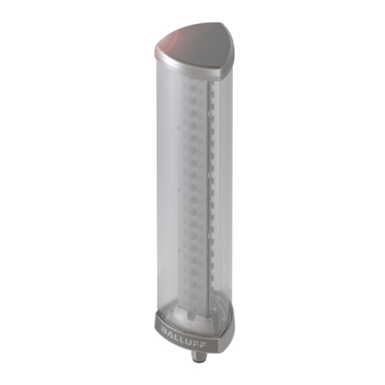
Getting Started 3.1 Overview Fig. 3-1: BNI IOL-802-000-Z036 1 Cap 6 Segment 5 2 Segment 1 7 Socket 3 Segment 2 8 M12 connector 4 Segment 3 9 M18 thread for mounting 5 Segment 4 10 Status LED www.balluff.com... -
Page 7: Mechanical Connection
Balluff / IO-Link BNI IOL-802-000-Z036 Getting Started 3.2 Mechanical The BNI IOL-802-000-Z036 modules are attached by using an M18 nut. connection 3.3 Electrical The BNI IOL-802-000-Z036 modules require no separate supply voltage connection. Power connection is provided through the IO-Link interface by the host IO-Link Master. -
Page 8: Short Description Of The Functionality
Getting Started 3.6 Short description The functionality of the Balluff status light module can be controlled through process data of the and SPDU registers. It has three main mode of functionality: functionality Segment mode Level mode Runlight mode With the help of these three modus various warning and indication signals can be indicated. - Page 9 Balluff / IO-Link BNI IOL-802-000-Z036 Getting Started The LED bar at increasing input data and no color dominance. (The virtual segments can be seen on the left side.) Of course the segment 2 or 4 does not have to be the same color as segment 3 or 5.
- Page 10 Getting Started The LED bar at increasing input data, all the colors are dominant. Seg. 1 Seg. 2 Seg. 3 Seg. 4 Seg. 5 www.balluff.com...
-
Page 11: Runlight Mode
Balluff / IO-Link BNI IOL-802-000-Z036 Getting Started By default the 20 LED are divided into equal virtual segments. The height of the virtual segments can be modified too. There are four SPDU register (Level mode limit x-y SPDU register), in which the limits of the virtual segments can be modified. For example: If the input level value is higher than the limit value of the 2. -
Page 12: Io-Link Interface
IO-Link Revision Frame typ Process data cycle time* 5 ms 30 ms * by min. cycle time 4.2 Process data / BNI IOL-802-000-Z036, Smart Light Mode Output data Byte Byte Bit definitions Bit 0-2 / 4-6 Bit 3 / 7 in segment 0 –... - Page 13 Balluff / IO-Link BNI IOL-802-000-Z036 IO-Link Interface BNI IOL-802-000-Z036, Level Mode Byte Level value Byte Level value: 8, 10, 12, 14 or 16 bit value for level indicator. The resolution can be set in Level resolution SPDU register. The Level value is always left justified.
- Page 14 IO-Link Interface BNI IOL-802-000-Z036, Runlight Mode Byte Byte In runlight mode the process data has no meanings, only SPDU registers are controlling the functionality. www.balluff.com...
-
Page 15: Parameter Data/Request Data
Balluff / IO-Link BNI IOL-802-000-Z036 IO-Link Interface 4.3 Parameter data/ SPDU Object name Length Range Default Value Request data Index Index Sub- index Vendor ID 2 Byte 0378 Device ID 3 Byte 050A01 Vendor name 7 Byte BALLUFF Vendor text 15 Byte www.balluff.com... - Page 16 1 Byte background color Runlight mode …7 1 Byte running color Runlight mode …3 number of running 1 Byte segments …3 Supply monitoring 1 Byte …7F7F7F Brightness 3 Byte 7F7F7F …5 Blinking frequency 1 Byte …1F Blinking mode 1 Byte www.balluff.com...
-
Page 17: Mode 40Hex
Balluff / IO-Link BNI IOL-802-000-Z036 IO-Link Interface Mode 40 The operating mode of the module. 0 = Segment mode 1 = Level mode 2 = Runlight mode Number of Number of the segments. Values from 1 to 5 can be set. -
Page 18: Runlight Mode, Background Color 4Dhex
011 = yellow 100 = blue 101 = reserved 110 = reserved 111 = white Runlight mode, Number of the running segments. Each segment contains 4 LED. Values between 1 and 3 number of can be set running segments www.balluff.com... -
Page 19: Supply Monitoring 50Hex
Balluff / IO-Link BNI IOL-802-000-Z036 IO-Link Interface Supply monitoring Index Under voltage Us 0: Us voltage is Ok 1: Low voltage on IO-Link pin 1 LED Voltage failure 0: LED Voltage is Ok 1: LED Voltage failure Brightness At three byte SPDU register sets the brightness for each channel (red, green, blue). Values from 0x00 to 0x7F are accepted. -
Page 20: Blinking Frequency 52Hex
Access Denied 0x8030 Parameter Value out of Range 0x8033 Paremeter length overrun 0x8034 Parameter length underrun 4.5 Events IO-Link Revision 1.0 Event Code Description 0x5112 Low sensor voltage (US) IO-Link Revision 1.1 Event Code Description 0x5111 Low sensor voltage (US) www.balluff.com... -
Page 21: Technical Data
Balluff / IO-Link BNI IOL-802-000-Z036 Technical Data 5.1 Dimensions 5.2 Mechanical data Housing Material Polycarbonate transparent - die-cast zinc housing IO-Link-Port M12, A-coded, male Enclosure rating IP67 (only when plugged-in and threaded-in) Weight ca. 500 g Dimensions 278 × 60 × 60 mm (L ×... -
Page 22: Led Indicator
It can be switched on, switched of and flashing. The flashing LED has the following timings. Communication error Communication ok LED is flashing Supply modul LED is static off undervoltage LED is flashing Supply module ok LED is static on www.balluff.com... -
Page 23: Appendix
Bus connection M12 external thread, Module fastening M18 external thread 6.2 Order information Type Order Code BNI IOL-802-000-Z036 BNI0072 Included material BNI IOL-802-000-Z036 consists of the following components: signal light M18x1 nut rubber foot screw M4 ... - Page 24 Notes www.balluff.com...
- Page 25 Balluff GmbH Schurwaldstrasse 9 73765 Neuhausen a.d.F. Germany Tel. +49 7158 173-0 Fax +49 7158 5010 www.balluff.com balluff@balluff.de...
Need help?
Do you have a question about the BNI IOL-802-000-Z036 and is the answer not in the manual?
Questions and answers