
Subscribe to Our Youtube Channel
Related Manuals for Balluff BNI IOL-802-000-Z036

Summary of Contents for Balluff BNI IOL-802-000-Z036
- Page 1 BNI IOL-802-000-Z036 BNI IOL-802-000-Z036-006 BNI IOL-802-000-Z037 BNI IOL-802-000-Z037-006 Smart Light User’s Guide...
-
Page 2: Table Of Contents
2.1 Intended use 2.2 Installation and startup 2.3 General safety instructions 2.4 Resistance to aggressive substances Hazardous voltage Getting Started 3.1 Overview BNI IOL-802-000-Z036 3.2 Overview BNI IOL-802-000-Z037 3.3 Mechanical connection 3.4 Electrical connection 3.5 Function ground 3.6 IO-Link connection... - Page 3 Balluff / IO-Link BNI IOL-802-000-Z03x Flexible mode, LEDxx settings A1hex…B4hex User color FChex Limit type FDhex Buzzer type FEhex 4.4 Errors 4.5 Events Technical Data 5.1 Dimensions 5.2 Mechanical data 5.3 Electrical data 5.4 Operating conditions 5.5 LED indicator Status LED Appendix 6.1 Product ordering code...
-
Page 4: Notes To The User
Cross-references indicate where additional information on the topic can be found. 1.3 Symbols Attention! This symbol indicates a security notice which must be observed. Note This symbol indicates general notes. Abbreviations Balluff Networking Interface Direct Parameter Page Electromagnetic Compatibility Function Earth IO-Link ISDU Indexed Service Data Unit 1.5 Deviating views... -
Page 5: Safety
Balluff / IO-Link BNI IOL-802-000-Z03x Safety 2.1 Intended use This guide describes the Balluff BNI IOL-802-000-Z03x for the application as status light module. Hereby it is about an IO-Link device which communicates by means of IO-Link protocol with the superordinate IO-Link master assembly. -
Page 6: Getting Started
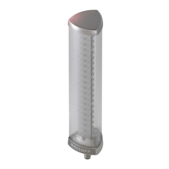
Getting Started 3.1 Overview BNI IOL- 802-000-Z036 Fig. 3-1: BNI IOL-802-000-Z036 1 Cap 9 M18 thread for mounting 17 LED14 25 LED06 2 Segment 1 10 Status LED 18 LED13 26 LED05 3 Segment 2 11 LED20 19 LED12 27 LED04... -
Page 7: Overview Bni Iol-802-000-Z037
Balluff / IO-Link BNI IOL-802-000-Z03x Getting Started 3.2 Overview BNI IOL- 802-000-Z037 Fig. 3-2: BNI IOL-802-000-Z037 1 Cap with buzzer 9 M18 thread for mounting 17 LED14 25 LED06 2 Segment 1 10 Status LED 18 LED13 26 LED05 3 Segment 2... -
Page 8: Mechanical Connection
Module versions Version Description Maximum 5 segment configurable signal light with BNI IOL-802-000-Z036 level meter, runlight mode and flexible mode. Maximum 5 segment configurable signal light with BNI IOL-802-000-Z036-006 level meter, runlight mode and flexible mode. In die- cast zinc housing with chrome finishing. -
Page 9: Short Description Of The Functionality
Balluff / IO-Link BNI IOL-802-000-Z03x Getting Started 3.7 Short description The functionality of the Balluff status light module can be controlled through process data of the and ISDU registers. It has four main mode of functionality: functionality Segment mode ... - Page 10 The LED bar at increasing input data and no color dominance. (The virtual segments can be seen on the left side.) Of course the segment 2 or 4 does not have to be the same color as segment 3 or 5. Seg. 1 Seg. 2 Seg. 3 Seg. 4 Seg. 5 www.balluff.com...
- Page 11 Balluff / IO-Link BNI IOL-802-000-Z03x Getting Started The LED bar at increasing input data, all the colors are dominant. Seg. 1 Seg. 2 Seg. 3 Seg. 4 Seg. 5 www.balluff.com...
-
Page 12: Runlight Mode
ISDU registers. One segment has a size of 4 LEDs. The number of the running segment can be set between 1 and 3. www.balluff.com... -
Page 13: Flexible Mode
3.12 Synchronisation In synchronisation mode you can syncronise functions (blinking, flashing, buzzer) of several Balluff SmartLights. The function is available in runlight- and segment mode. The synchronisation is controlled by 2 bits in the process data: (Sync Start and Sync Impluse). -
Page 14: Io-Link Interface
IO-Link Interface 4.1 IO-Link Data The BNI IOL-802-000-Z036 and BNI IOL-802-000-Z037 Smart Light modules have 3 byte output process data. The output process data has different meaning depending on the selected mode (segment mode, level mode, runlight mode or flexible mode). -
Page 15: Bni Iol-802-000-Z03X, Level Mode
Balluff / IO-Link BNI IOL-802-000-Z03x IO-Link Interface BNI IOL- Byte 802-000- Z03x, Level Mode 8 bit level value 10 bit level value 12 bit level value 14 bit level value 16 bit level value Byte Level value definitions The 8, 10, 12, 14 or 16 bit value for level indicator. The resolution can be set in Level resolution in level ISDU register. -
Page 16: Bni Iol-802-000-Z03X, Runlight Mode
Bit 7, Buzzer state Bit 5/6, Sync start/Sync impulse definitions (Only in case of BNI IOL-802-000-Z037) (available from software version 3.0) in runlight mode 0 – buzzer is off These bits are rising edge sensitive 1 – buzzer is on www.balluff.com... -
Page 17: Bni Iol-802-000-Z03X, Flexible Mode
Balluff / IO-Link BNI IOL-802-000-Z03x IO-Link Interface BNI IOL-802- Byte 000-Z03x, Flexible Mode Byte Bit 7, Buzzer state Bit 0-8/0-4, LEDxx state definitions (Only in case of BNI IOL-802-000-Z037) in flexible 0 – LED is off mode 0 – buzzer is off 1 –... -
Page 18: Parameter Data/Request Data
2 Byte 0378 050A01 Device ID 3 Byte 050A03 Vendor name 7 Byte BALLUFF Vendor text 15 Byte www.balluff.com BNI IOL-802-000-Z036 Product 20 Byte BNI IOL-802-000-Z036-006 name 24 Byte BNI IOL-802-000-Z037 BNI IOL-802-000-Z037-006 BNI007F Product ID 7 Byte BNI0072 Smart Light 5 segment... - Page 19 Balluff / IO-Link BNI IOL-802-000-Z03x IO-Link Interface ISDU Object name Length Range Default Value Index Sub- index Mode 1 Byte 0…3 Number of segments 1 Byte 1…5 Level type 1 Byte 0…1 Level resolution 1 Byte 0…4 Level mode 1 Byte …F...
- Page 20 0000FFFF01 LED20 settings**** 5 Byte …FFFFFFFFFF 0000FFFF01 User color*** 3 Byte …FFFFFF 008080 Limit type*** 1 Byte 0…1 Buzzer type** 1 Byte 0…3 **Only in case of BNI IOL-802-000-Z037 ***Available from software version 2.1 ****Available from software version 3.0 www.balluff.com...
-
Page 21: Mode 40Hex
Balluff / IO-Link BNI IOL-802-000-Z03x IO-Link Interface Mode The operating mode of the Smart Light can be selected in the Mode ISDU register. 0 = Segment mode 1 = Level mode 2 = Runlight mode 3 = Flexible mode* *Available from software version 3.0 Number of The number of the displayed segments can be set in this register. -
Page 22: Level Mode Limit X-Y 49Hex 4Ahex 4Bhex 4Chex
10 bit limit value 12 bit limit value 14 bit limit value 16 bit limit value Percent value: 0 – 100 Note Before changing the limit values, the Resolution and Limit type should be set to the desired value! www.balluff.com... -
Page 23: Runlight Mode, Background Color 4Dhex
Balluff / IO-Link BNI IOL-802-000-Z03x IO-Link Interface Runlight mode, Byte background color The background of the runlight effect can be set in this register. Bit 0-2, Background color 000 = Off 001 = Green 010 = Red 011 = Yellow... -
Page 24: Supply Monitoring 50Hex
0, 1, 2 or 3. Reading/writing the subindex 0 the whole 3 byte brightness data can be accessed. Subindex 1, 2 and 3 contains the brightness data for red, green and blue channels. Byte Index Brightness value for red Brightness value for green Brightness value for blue channel channel channel www.balluff.com... -
Page 25: Blinking Frequency / Runlight Speed 52Hex
Balluff / IO-Link BNI IOL-802-000-Z03x IO-Link Interface Blinking The frequency of the blinking in segment mode and the speed of the running segment in frequency / runlight mode can be set in this register. Values between 1 and 5 are accepted. One means the Runlight slowest and five means the fastest blinking or running speed. -
Page 26: User Color Fchex
Access Denied 0x8030 Parameter Value out of Range 0x8033 Parameter length overrun 0x8034 Parameter length underrun 4.5 Events IO-Link Revision 1.0 Event Code Description 0x5112 Low supply voltage (US) IO-Link Revision 1.1 Event Code Description 0x5111 Low supply voltage (US) www.balluff.com... -
Page 27: Technical Data
IP30 (only when plugged-in) BNI IOL-802-000-Z036-xxx: ca. 500 g Weight BNI IOL-802-000-Z037-xxx: ca. 570 g Dimensions BNI IOL-802-000-Z036-xxx: 309 × 60 × 60 mm (L × W × H, excluding connector) BNI IOL-802-000-Z037-xxx: 330.5 × 60 × 60 mm www.balluff.com... -
Page 28: Electrical Data
Ripple Current draw all segments off ≤ 40 mA @24V Current draw all segments white, BNI IOL-802-000-Z036-xxx: ≤ 400 mA @ 24V buzzer on BNI IOL-802-000-Z037-xxx: ≤ 410 mA @ 24V Volume of the buzzer module 100dB at 1m distance Tone frequency of the buzzer 2800 ±... -
Page 29: Led Indicator
Balluff / IO-Link BNI IOL-802-000-Z03x Technical Data 5.5 LED indicator Status LED Status LED Indicator Function Status LED Green, green flashing Status for supply and communication The status LED indicates the current status of the power supply and the communication. -
Page 30: Appendix
Appendix 6.1 Product ordering code BNI IOL-802-000-Z03x-xxx Balluff Networking Interface IO-Link Interface 802: Smart Light 5 Segment Standard version Mechanical design Die-cast zinc housing Polycarbonate transparent housing Bus connection M12 external thread, Module fastening M18 external thread Z036: Smart Light without buzzer... - Page 31 Balluff / IO-Link BNI IOL-802-000-Z03x Notes www.balluff.com...
- Page 32 Balluff GmbH Schurwaldstrasse 9 73765 Neuhausen a.d.F. Germany Tel. +49 7158 173-0 Fax +49 7158 5010 www.balluff.com balluff@balluff.de...
Need help?
Do you have a question about the BNI IOL-802-000-Z036 and is the answer not in the manual?
Questions and answers