Advertisement
Quick Links
User 's Ma nual
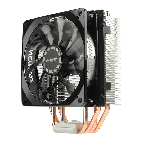
100% RAM compatibility Air CPU Cooler
©2017 ENERMAX TECHNOLOGY CORPORATION. All right reserved. Specifications are subject to
change without prior notice. Some trademarks may be claimed as the property of others.
Step 1-B
*Intel LGA 2011/2066
L
EN
Fasten the Intel LGA 2011/2066 screws to the motherboard.
Schrauben Sie die Montageschrauben für den Intel-LGA2011/2066-Sockel in die passenden
DE
Bohrungen Ihres Mainboards
FR
Fixez les vis Intel LGA 2011/2066 à la carte mère.
IT
Fissare le viti LGA 2011/2066 alla scheda madre
Wkręć śruby montażowe (platformy Intel LGA2011/2066) w odpowiednie otwory na płycie
PL
głównej.
ES
Fije los tornillos de Intel LGA 2011/2066 a la placa base.
RU
Затяните гайки «Intel LGA 2011/2066» на материнской плате.
TW
將LGA2011/2066螺絲固定於主板上。
CN
将LGA2011/2066螺丝固定在主板上。
KR
마더보드에Intel LGA 2011/2066 나사로 고정해주세요.
JP
Intel LGA 2011/2066用スクリューをマザーボード表面から挿し入れて下さい。
ID
Kencangkan sekrup Intel LGA 2011/2066 ke Motherboard.
FA
LGA 2011/2066
Part List
A
B
C
CPU Cooler
Fan
Back Plate
D
E
F
Position Screw
Intel Mounting Plate
G
H
I
AMD Mounting Plate
Washer
Insulating Pad
J
K
L
Mounting Plate
Spring Screw
Intel LGA 2011/2066
Screw
Screw
M
N
O
Pressure Mounting
Thermal Grease
Fan Bracket
Plate
P
Q
R
Bracket Screw
Vibration-absorbing
Pad
*
Notice: Actual specifications / product parts may vary according to different regions or countries.
Step 2
*For Intel installation
K
F
Install the Intel mounting plates with the arrow marks towards to the CPU, then fasten them with
EN
spring screws.
Richten Sie die Intel-Montagehalterungen mit den Pfeilsymbolen in Richtung der CPU aus und
DE
schrauben Sie sie mit den Federschrauben fest.
Installez les plaques de montage Intel avec les flèches vers le CPU, puis fixez-les avec des vis
FR
à ressort.
Installare le piastre di montaggio con il simbolo della freccia verso la CPU, successivamente
IT
fissarle con le viti a molla.
Ustaw wsporniki mocujące Intel-a z strzałką w kierunku do procesora i dokręć je do płyty
PL
głównej za pomocą srub sprężystych.
Instale el soporte de montaje de Intel con las flechas hacia la CPU, luego fíjelo con los tornillos
ES
correspondientes.
Установите крепёжные пластины Intel с стрелками в направлении к процессору, затем
RU
закрепите их пружинными винтами.
TW
將Intel支架,將刻印箭頭朝CPU方向,以彈簧螺絲安裝上主板。
CN
将Intel支架的刻印箭头朝CPU方向,用弹簧螺丝安装到主板上。
KR
Intel 마운팅 판을 화살표가 있는CPU쪽으로 설치해, 스프링 나사로 고정해주세요.
Intel用マウントプレートを図のような向きでポジションスクリューに挿し入れ、スプリングスクリューで固定してくださ
JP
い。
Pasang Mounting Plate Intel dengan tanda panah ke arah CPU. Kemudian kencangkan dengan
ID
sekrup spring.
Intel mounting plates
FA
Step 1-A-1
Installation
*LGA775/1150/1155/1156/1366
2
H
LGA1366
C
LGA115X
LGA775
1
D
Insert the position screws into the proper holes on the back plate. Then use the washers to fix
EN
the position screws.《 If your CPU platform is Intel LGA2011/2066, please skip to step 1-B》
Drehen Sie die Montageschrauben in die zu Ihrem Sockel passende Bohrung in der Backplate
DE
wie abgebildet an.《Wenn Sie einen LGA2011/2011-3/2066-Sockel verwenden, gehen Sie bitte
zu Schritt 1-B über》
Insérez les vis de position dans les trous correspondant à votre socket du CPU sur la plaque
FR
arrière. Puis fixez-les avec les rondelles.《S'il s'agit d'un processeur Intel LGA2011/2066,
passez à l'étape 1-B》
Inserire le viti di montaggio nel foro appropriato nella piastra posteriore come mostrato nella
IT
figura sotto.《Se la piattaforma CPU è Intel LGA2011/2066, si prega di passare al punto 1-B》
Włóż śruby pozycjonujące do odpowiednich otworów na płycie tylnej. Następnie użyj podkładek
PL
w celu zamocowania śrub pozycjonujących.《Platformy Intel LGA2011/2066: Proszę przejść do
punktu 1-B》
Inserte los tornillos de montaje en el agujero correspondiente en la placa trasera como se ve en
ES
la imagen abajo. 《Si su plataforma de CPU es Intel LGA2011/2066, por favor vaya
directamente al paso 1-B》
Установите винты для крепежной пластины в соответствующие отверстия для вашего
RU
процессора. Установите промежуточные стойки на винты.《 Если ваша CPU платформа
является Intel LGA2011/2011-3/2066, пожалуйста, перейдите к шагу номер 1-B》
在背板上依系統CPU腳位所標示的孔位插入定位螺絲並套上墊圈固定。《如果您的主機板是Intel
TW
LGA2011/2066,請直接跳至步驟1-B》
在背板上根据系统CPU脚位所标示的孔位插入定位螺丝并套上垫圈固定。《如果您的主板是Intel
CN
LGA2011/2066,请直接跳至步骤1-B》
브라켓 구멍에 알맞은 나사를 삽입 한 후 와셔를 사용하여 나사를 고정하세요. 《CPU 플랫폼이
KR
Intel LGA2011/2066 인경우,Step 1-B로 가세요》
ポジションスクリューをバックプレートの適切なネジ穴に挿入し、ワッシャーを使用してポジションスクリューを固定
JP
して下さい。 《 Intel LGA2011/2066をお使いの方はステップ1-Bに進んでください》
Masukkan sekrup ke dalam lubang yang tepat pada back plate. Kemudian gunakan
ID
washers/ring untuk mengencangkan sekrup. 《 Jika Platform CPU Anda Intel LGA 2011/2066,
lanjutkan ke langkah 1-B 》
ﭘﻴﭽﻬﺎی ﻣﺮﺑﻮﻃﻪ ﺭﺍ ﺩﺭﻭﻥ ﻣﺤﻠﺸﺎﻥ ﺭﻭی ﺑﮏ ﭘﻠﻴﺖ ﻗﺮﺍﺭ ﺩﻩﻴﺪ. ﺳﭙﺲ ﺍﺯ ﻭﺍﺷﺮﻩﺎ ﺑﺮ ﺗﺜﺒﻴﺘﺸﺎﻥ
FA
1-B
LGA2011/2066
《
Step 3-1
*For AMD installation
AM3(+) / AM2(+)
FM1 / FM2(+)
2
AM4
H
1
C
D
Insert the position screws into the proper holes on the back plate. Then use the washers to fix
EN
the position screws.
Drehen Sie die Montageschrauben in die zu Ihrem Sockel passende Bohrung in der Backplate
DE
wie abgebildet an.
Insérez les vis de position dans les trous correspondant à votre socket du CPU sur la plaque
FR
arrière. Puis fixez-les avec les rondelles.
Inserire le viti di montaggio nel foro appropriato nella piastra posteriore come mostrato nella
IT
figura sotto.
Włóż śruby pozycjonujące do odpowiednich otworów na płycie tylnej. Następnie użyj podkładek
PL
w celu zamocowania śrub pozycjonujących.
Inserte los tornillos de montaje en el agujero correspondiente en la placa trasera como se ve
ES
en la imagen abajo.
Установите винты для крепежной пластины в соответствующие отверстия для вашего
RU
процессора. Установите промежуточные стойки на винты.
TW
在背板上依系統CPU腳位所標示的孔位插入定位螺絲並套上墊圈固定。
CN
在背板上根据系统CPU脚位所标示的孔位插入定位螺丝并套上垫圈固定。
KR
브라켓 구멍에 알맞은 나사를 삽입 한 후 와셔를 사용하여 나사를 고정하세요.
JP
ポジションスクリューをバックプレートの適切なネジ穴に挿入し、ワッシャーを使用してポジションスクリューを固定
して下さい。
Masukkan sekrup ke dalam lubang yang tepat pada back plate. Kemudian gunakan
ID
washers/ring untuk mengencangkan sekrup.
FA
ﭘﻴﭽﻬﺎی ﻣﺮﺑﻮﻃﻪ ﺭﺍ ﺩﺭﻭﻥ ﻣﺤﻠﺸﺎﻥ ﺭﻭی ﺑﮏ ﭘﻠﻴﺖ ﻗﺮﺍﺭ ﺩﻩﻴﺪ. ﺳﭙﺲ ﺍﺯ ﻭﺍﺷﺮﻩﺎ ﺑﺮ ﺗﺜﺒﻴﺘﺸﺎﻥ ﺍﺳﺘﻔﺎﺩﻩ ﮐﻨﻴﺪ
Step 1-A-2
*LGA775/1150/1155/1156/1366
E
Install the back plate on to the back of the motherboard. Put the stand-offs into the back plate
EN
screws.
Schieben Sie die Montageschrauben mit der Backplate durch die passenden Bohrungen des
DE
Mainboards. Fixieren Sie die Backplate mit den Abstandshaltern.
Installez la plaque arrière à l'arrière de la carte mère. Mettez les entretoises dans les vis de la
FR
plaque arrière,
Installare il backplate nella parte posteriore della scheda madre. Posizionare i distanziatori sulle
IT
viti del backplate.
PL
Umieść płytę mocującą pod płytą główną i przykręć ją za pomocą śrub dystansowych.
Instale el back plate en la parte posterior de la placa base. Coloque los separadores en los
ES
tornillos del back plate.
Установите крепёжную пластину на обратной стороне материнской платы. Установите
RU
промежуточные стойки на винты.
TW
將套上定位螺絲的背板,裝於主機板背面,再將套筒放入定位螺絲內。
CN
将套上定位螺丝的背板,装在主机板背面,再将套筒放入定位螺丝内。
KR
마더보드 뒷면에 Back Plate을 설치해주세요. Back Plate 나사에 지지대를 넣으세요.
マザーボードの背面にバックプレートを設置し、表面にでたポジションスクリューにプラスチック製のスタン
JP
ドオフを装着してください
※スタンドオフには上面/下面の区別があります。
ID
Pasang back plate ke belakang motherboard. Masukkan stand-off ke sekrup back plate.
FA
stand-off
ﺍﺳﺘﻔﺎﺩﻩ ﮐﻨﻴﺪ
》
Step 3-2
*For AMD installation
I
EN
Stick the insulating pad on the appropriate position.
DE
Kleben Sie die Entkopplungsplatten an die vorgesehenen Stellen auf der Backplate.
FR
Collez le coussinet d'isolation à l'emplacement prévu à cet effet.
IT
Attaccare il foglio isolante nella posizione appropriata.
PL
Przyklej wkładkę izolującą w odpowiedniej pozycji.
ES
Pegue la hoja aislante en la posición adecuada.
RU
Наклейте изоляционную прокладку на соответствующую позицию.
TW
黏貼絕緣墊片於背板相對位置。
CN
将绝缘垫片粘贴到背板相对位置。
KR
알맞은 위치에 방음 패드를 부착하세요.
JP
インシュレーターパッ ドを適切な位置に取り付けてください。
ID
Tempelkan bantalan insulasi pada posisi yang tepat.
FA
ﭘﺪ ﻋﺎﻳﻖ ﺭﺍ ﺩﺭ ﻣﺤﻞ ﻣﻨﺎﺳﺐ ﻧﺼﺐ ﮐﻨﻴﺪ
Advertisement

Related Manuals for ENERMAX ETS-T40fit


Summary of Contents for ENERMAX ETS-T40fit
- Page 1 Pasang back plate ke belakang motherboard. Masukkan stand-off ke sekrup back plate. lanjutkan ke langkah 1-B 》 ﭘﻴﭽﻬﺎی ﻣﺮﺑﻮﻃﻪ ﺭﺍ ﺩﺭﻭﻥ ﻣﺤﻠﺸﺎﻥ ﺭﻭی ﺑﮏ ﭘﻠﻴﺖ ﻗﺮﺍﺭ ﺩﻩﻴﺪ. ﺳﭙﺲ ﺍﺯ ﻭﺍﺷﺮﻩﺎ ﺑﺮ ﺗﺜﺒﻴﺘﺸﺎﻥ stand-off ©2017 ENERMAX TECHNOLOGY CORPORATION. All right reserved. Specifications are subject to ﺍﺳﺘﻔﺎﺩﻩ ﮐﻨﻴﺪ LGA2011/2066 《...
- Page 2 Step 3-3 Step 3-4 Step 4 Step 5 *For AMD installation *For AMD installation Combine the AMD mounting plates on the Intel mounting plates (arrow marks on the Intel plates Install the back plate on to the back of the motherboard. Put the stand-offs into the back plate Apply the thermal grease evenly onto the CPU surface.
Need help?
Do you have a question about the ETS-T40fit and is the answer not in the manual?
Questions and answers