Advertisement
Quick Links
Advertisement

Subscribe to Our Youtube Channel
Related Manuals for ENERMAX LIQFusion Series


Summary of Contents for ENERMAX LIQFusion Series
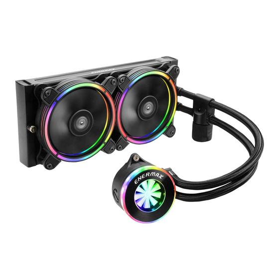
- Page 1 A l l - I N - O N E L I Q U I D C P U C O O L E R...
- Page 2 Index Limited Warranty Specification Part list Intel Installation Motherboard Sync RGB Control Box Refilling Coolant...
-
Page 3: Limited Warranty
This ENERMAX Technology Corporation product is warranted to be free from defects in material and workmanship for a period of two (2) years from the date of purchase. ENERMAX Technology Corporation agrees to repair or replace the product, at its own option and at no... -
Page 4: Specification
Specification ELC-LF240-RGB ELC-LF360-RGB Model Material Copper base with Aluminum Radiator Bearing Ceramic bearing MTBF 50,000 hrs Motor Speed Pump 5,000 rpm ± 10% Rated Voltage Rated Current (A) 0.18A Water Block Rated Current - RGB LED (A) 0.57A Dimension 277 x 120 x 27 mm 394 x 120 x 27 mm Radiator Material... - Page 5 Part List LIQFUSION 240 Cooler x 1 Fan x 2 Back Plate x 1 Position Plate x 1 Position Screw x 4 Case Screw x 8 Fan Screw x 8 Stand-off x 4 Set Screw x 4 Washer x 4 PWM Y cable x 1 Molex Adaptor x 1 Scraper x 1...
- Page 6 Part List LIQFUSION 360 Cooler x 1 Fan x 3 Back Plate x 1 Position Plate x 1 Position Screw x 4 Case Screw x 12 Fan Screw x 12 Stand-off x 4 Set Screw x 4 Washer x 4 PWM 3 to 1 cable x 1 Molex Adaptor x 1 Scraper x 1...
-
Page 7: Liqfusion
A l l - I N - O N E L I Q U I D C P U C O O L E R Installation - 5 -... - Page 8 Step 1 Installation Attach the fan and the radiator to the chassis Schrauben Sie den Lüfter und den Radiator am Gehäuse fest. Fixez le ventilateur et le radiateur sur le châssis Fissare la ventola e il radiatore al case Fijar el ventilador y el radiador a la caja Zamontuj wentylator i radiator na obudowie komputerowej.
- Page 9 Step 2-A-1 Installation LGA115X LGA1366 All AM2/AM3/ FM1/FM2 bracket Insert the position screws into the proper holes on the back plate. Then use the washers to fix the position screws. (If your CPU platform is Intel LGA 2011/2011-3/2066, please skip to step 2-B) Stecken Sie die Positionsschrauben in die entsprechenden Löcher auf der Backplate passend zu Ihrenm CPU-Sockel.
- Page 10 Step 2-A-2 Installation Install the back plate on the back of motherboard, place the washer into the position screw and fix them with stand-off. Installieren Sie die Backplate auf der Rückseite des Mainboards, legen Sie die Unterlegscheibe auf die Positionsschraube und fixieren Sie sie mit dem Abstandshalter. Installez la plaque arrière (C) sous la carte-mère, placez les rondelles (J) dans les vis (E) de position puis fixez-les avec les écrous (F) boulons.
- Page 11 Step2-A-3 Installation Place position plate on stand-off and use set screw to fix. Legen Sie die Positionsplatte auf die Abstandshalter und verwenden Sie die Feststellschrauben zum Fixieren. Placez la plaque (D) de position sur les écrous (F) boulons et utilisez les vis (I) pour les fixer. Collocare la piastra di posizione sui distanziali e utilizzare le viti per fissare.
- Page 12 Step2-B Installation LGA 2011 / 2011-3 / 2066 Place position plate on stand-off and use position screw to fix. (Socket LGA 2011/2011-3/2066 does not require the back plate). Legen Sie die Positionsplatte auf die Abstandshalter und verwenden Sie die Positionsschrauben zum Fixieren.
- Page 13 Step 3 Installation Apply the thermal grease evenly on the CPU surface Verteilen Sie gleichmäßig eine dünne Schicht Wärmeleitpaste auf der CPU-Oberfläche. Appliquez une couche uniforme de pâte thermique sur la surface du CPU Applicare in modo uniforme la pasta termica sulla superficie della CPU Aplicar de forma uniforme la pasta térmica en la superficie de la CPU Nałóź...
- Page 14 Step 4 Installation Remove the protect film from the cold-plate. Entfernen Sie die Schutzfolie von der Kühlplatte der Pumpe. Retirez le film protecteur de la plaque-froide. Rimuovere la pellicola di protezione dalla piastra di raffreddamento. Quite la película de protección del bloque de refrigeración. Zdjąć...
- Page 15 Step 5 Installation Place the waterblock on the CPU and tighten the two screws. Setzen Sie den Wasserblock auf die CPU und ziehen Sie die beiden Schrauben fest. Placez la waterblock sur le CPU et serrez les 2 vis. Posizionare il waterblock sulla CPU e avvitare le due viti. Posicionar el bloque de refrigeración en la CPU y fijar los dos tornillos.
- Page 16 Step 6 Installation Pump Pump 3 pin 4 pin Connect the pump power connector to the motherboard. Notice: If you recognize that your mainboard's CPU fan or PWM sockets do not provide enough voltage to power the pump, please use the included 4-pin Molex adaptor and connect the pump directly to your PSU. Schließen Sie den Stromstecker der Pumpe am Mainboard an.
- Page 17 Step 7 Installation PWM Y cable 4 pin Connect the fan connector to the motherboard Schließen Sie den 4-Pin-PWM-Stecker des Lüfters am Mainboard an. Branchez le connecteur du ventilateur à la carte-mère Collegare il connettore della ventola alla scheda madre Conecte el conector del ventilador a la placa madre Podłącz wtyczkę...
- Page 18 Motherboard Sync - 16 -...
- Page 19 Motherboard Sync Addressable RGB Header If the motherboard DOES support the addressable RGB (ADD headers): connect the RGB Sync cable to the motherboard. Wenn das Mainboard adressierbare RGB-(ADD)-Header unterstützt: Verbinden Sie das RGB-Sync-Kabel mit dem Mainboard. Si la carte mère prend en charge le connecteur RGB (ADD headers): connectez le câble de synchronisation RGB à...
-
Page 20: Motherboard Sync
Motherboard Sync For GIGABYTE motherboards, the pin assignment* of the addressable RGB headers is different from those of LIQFUSION. Therefore, when you install the cooler onto the motherboards, please connect the RGB Sync cable to the adapter (both cables are included in the LIQFUSION package). Next step please connect the RGB Sync adapter to the motherboard addressable RGB header, to enrich and perfect your lighting experience. - Page 21 Motherboard Sync W przypadku płyt głównych GIGABYTE układ połączeń na pinach* adresowanego złącza RGB różni się od standardowego układu LIQFUSION. Dlatego przy instalowaniu modułu na tych płytach głównych należy podłączyć kabel synchronizacyjny RGB znajdujący się w pakiecie LIQFUSION do adaptera, a następnie podłączyć...
-
Page 22: Rgb Control Box
RGB Control Box For non-addressable RGB motherboard - 20 -... - Page 23 RGB Control Box When you install the cooler onto the motherboard, please connect the RGB Sync cable to the water block, and then connect the power connectors to RGB control box. Meanwhile, connect the SATA power cable to PC power supply SATA connector. Wenn Sie den Kühler auf dem Motherboard installieren, schließen Sie bitte das RGB-Sync-Kabel an den Wasserblock und...
- Page 24 Lighting Mode (GREEN) Light effect mode (GREEN) Effect up/down Mode The 4 LED colors indicate the different modes: GREEN (Light Effect), RED (Effect Speed), BLUE (Brightness), YELLOW (Auto-run). 1. Press “M” until you reach the Light Effect Mode (GREEN). 2. To change the effect, press the ▲ or ▼ button. 3.
- Page 25 Lighting Mode (GREEN) Les 4 couleurs des diodes indiquent les différents modes: VERT (Effets lumineux), ROUGE (Vitesse), BLEU (Luminosité) et JAUNE (Mode Auto). 1. Appuyez sur “M” jusqu’à ce que vous atteigniez le mode Effets lumineux (diode verte). 2. Pour faire varier l’effet, appuyez sur▲ou▼. 3.
- Page 26 Lighting Mode (GREEN) Znaczenie 4 kolorów światła LED: ZIELONE (tryb efektu światła), CZERWONE (tryb szybkości), NIEBIESKIE (tryb podświetlenia), ŻÓŁTE (automatyczne uruchamianie). 1. Naciśnij "M", aby przełączyć efekt, szybkość zmiany światła, podświetlenie i automatyczne uruchamianie. 2. W celu zmiany koloru, naciśnij przycisk▲lub▼, aby uruchomić jeden z 10, wstępnie ustawionych efektów światła.
- Page 27 Lighting Mode (GREEN) 緑色 (ライト効果) 、 赤色 (エフェク トスピード) 、 青色 (明るさ) 、 黄色 (オートラン) の4つのLEDカラーは、 異 なるモードを示します。 1. ライトエフェク トモード (緑色) になるまで "M"を押します。 2. エフェク トを変更するには、 ▲または▼ボタンを押します。 3. 10種のプリセッ トライト効果 : 1) レーシング - レインボー (デフォルト) 2) 呼吸 – レインボー 3) フラッシュレインボー...
- Page 28 Speed Mode (RED) Effect Speed Mode (RED) Speed up/down Mode 1. Press “M” until you reach the Effect Speed Mode (RED). 2. To change the effect speed, press the▲or▼button. 1. Drücken Sie "M", bis Sie den Effektgeschwindigkeitsmodus (ROT) erreichen. 2. Um die Effektgeschwindigkeit zu ändern, drücken Sie die Taste▲oder▼. 1.
- Page 29 Auto-run (YELLOW) Auto-run (YELLOW) Mode 1. Press “M” until you reach Auto-run (YELLOW). 2. In Auto-run Mode all 10 pre-set light effects run in a loop. 1. Drücken Sie "M", bis Sie den Auto-Run-Modus (GELB) erreichen. 2. Im Auto-Run-Modus laufen alle 10 voreingestellten Lichteffekte in einer Schleife. 1.
- Page 30 Brightness Mode (BLUE) Brightness mode (BLUE) Brightness up/down Mode 1. Press “M” until you reach the Brightness Mode (BLUE). 2. To adjust the brightness, press the▲or▼button. 3. Press “M” in any mode for 3 seconds to turn-off the light. Press “M” again to turn on the light and continue with the previous effect.
- Page 31 Brightness Mode (BLUE) Brightness mode (BLUE) Brightness up/down Mode 1. 明暗模式下,指示燈亮藍燈;此時按▲▼鍵可調整燈的明暗度。 2. 按 鍵可切換到其他模式。 3. 任一模式下長按3秒 鍵會關機;關機狀態下再按 鍵會開機並回到上次關機前的燈型模式。 1. 明暗模式下,指示灯亮蓝灯;此时按▲▼键可调整灯的明暗度。 2. 按 键可切换到其它模式。 3. 任一模式下长按 秒 键会关机;关机状态下再按 键会开机并回到上次关机前的灯型模式。 1. 明るさモード (青) に達するまで "M"を押します。 2. 明るさを調整するには、 ▲または▼ボタンを押します。 3. 任意のモードで 「M」 を3秒間押して、 ライトを消灯させます。 "M"をもう一度押してライトを点灯させ、 前 のエフェク...
- Page 32 A l l - I N - O N E L I Q U I D C P U C O O L E R Refilling Coolant - 30 -...
- Page 33 Important Please follow the refilling instruction on the manual to avoid warranty invalidation. * If the flow meter is not rotating. * Any damage caused by improper use or failure to operate in accordance with the manual is not warranted. * Please perform this operation outside the chassis.
-
Page 34: Refilling Coolant
Step A Refilling Coolant If the flow indicator can not rotate, please refill the coolant. (Please perform this operation outside the chassis). Loose waterblock two screws on the CPU, open the filler cap from the waterblock. Refill the adequate coolant into the waterblock. After refilling, firmly bolt the filler cap back to the waterblock. - Page 35 Step A Refilling Coolant Jeśli wskaźnik przepływu nie obraca się, dolej czynnika chłodzącego. (Tę czynność wykonaj poza obudową). Poluzuj dwie śruby na bloku wodnym CPU i zdejmij nasadkę wlewu. Dolej odpowiednią ilość czynnika chłodzącego do bloku wodnego. Po napełnieniu mocno dokręć nasadkę wlewu do bloku wodnego.
- Page 36 Step B Refilling Coolant - 34 -...
- Page 37 Step C Refilling Coolant Apply the thermal grease evenly on the CPU surface Verteilen Sie gleichmäßig eine dünne Schicht Wärmeleitpaste auf der CPU-Oberfläche. Appliquez une couche uniforme de pâte thermique sur la surface du CPU Applicare in modo uniforme la pasta termica sulla superficie della CPU Aplicar de forma uniforme la pasta térmica en la superficie de la CPU Nałóź...
- Page 38 Step D Refilling Coolant Place the waterblock on the CPU and tighten the two screws. Setzen Sie den Wasserblock auf die CPU und ziehen Sie die beiden Schrauben fest. Placez la waterblock sur le CPU et serrez les 2 vis. Posizionare il waterblock sulla CPU e avvitare le due viti.
- Page 39 Step E Refilling Coolant Pump Pump 3 pin 4 pin Connect the pump power connector to the motherboard. Notice: If you recognize that your mainboard's CPU fan or PWM sockets do not provide enough voltage to power the pump, please use the included 4-pin Molex adaptor and connect the pump directly to your PSU.
- Page 40 © 2019 Enermax Technology Corporation. All rights reserved. Technical changes, printing errors and mistakes excepted.
Need help?
Do you have a question about the LIQFusion Series and is the answer not in the manual?
Questions and answers