Advertisement
Quick Links
I N S T A L L A T I O N I N S T R U C T I O N S
Instrucciones de instalación
Installationsanleitung
Instruções de Instalação
LVM2X2U
LVM3X3U
LVM3X2U
Istruzioni di installazione
Installatie-instructies
Instructions d´installation
LVM3X1UP
LVM2X2UP
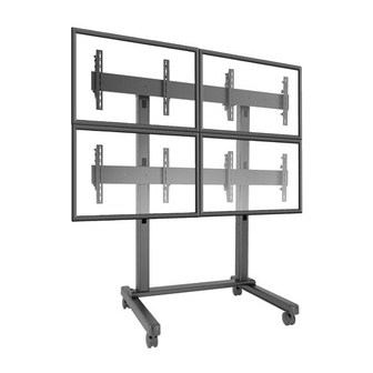
Video Wall Carts
Spanish Product Description
German Product Description
Portuguese Product Description
Italian Product Description
Dutch Product Description
French Product Description
LVM Series
LVM3X2UP
Advertisement


Need help?
Do you have a question about the LVM2X2U and is the answer not in the manual?
Questions and answers