Table of Contents
Advertisement
Quick Links
Advertisement
Table of Contents

Subscribe to Our Youtube Channel
Related Manuals for METREL Power Master MI 2892


Summary of Contents for METREL Power Master MI 2892
- Page 1 Power Master MI 2892 Instruction manual Version 8.2.2 Code No. 20 752 217...
- Page 2 Mark on your equipment certifies that this equipment meets the requirements of the EU (European Union) concerning safety and interference causing equipment regulations © 2017 METREL No part of this publication may be reproduced or utilized in any form or by any means without permission in writing from METREL.
-
Page 3: Table Of Contents
MI 2892 Power Master Table of contents Introduction ..........................7 Main Features ..........................7 Safety considerations ........................8 Applicable standards ........................9 Abbreviations..........................10 Description ..........................20 Front panel ..........................20 Connector panel ........................21 Bottom view ..........................22 Accessories ..........................22 2.4.1 Standard accessories ...................... - Page 4 MI 2892 Power Master Table of contents 3.15 Waveform/inrush recorder ....................... 66 3.15.1 Setup ..........................67 3.15.2 Capturing waveform ......................69 3.15.3 Captured waveform ......................70 3.16 Transient recorder ........................72 3.16.1 Setup ..........................72 3.16.2 Capturing transients ......................73 3.16.3 Captured transients ......................
- Page 5 MI 2892 Power Master Table of contents 5.1.4 Frequency measurement ....................150 5.1.5 Modern Power measurement ..................... 151 5.1.6 Classic Vector and Arithmetic Power measurement ............156 5.1.7 Energy ..........................159 5.1.8 Harmonics and interharmonics ................... 160 5.1.9 Signalling ..........................162 5.1.10 Flicker ..........................
- Page 6 MI 2892 Power Master Table of contents 6.2.20 Time and duration uncertainty ..................193 6.2.21 Temperature probe ......................193 6.2.22 Phase angle ........................194 6.2.23 400Hz systems specification ................... 194 6.2.24 VFD (Variable frequency drive) systems specification ............ 194 6.2.25 Differences in specification between 400Hz, VFD and 50/60 Hz systems ......
-
Page 7: Introduction
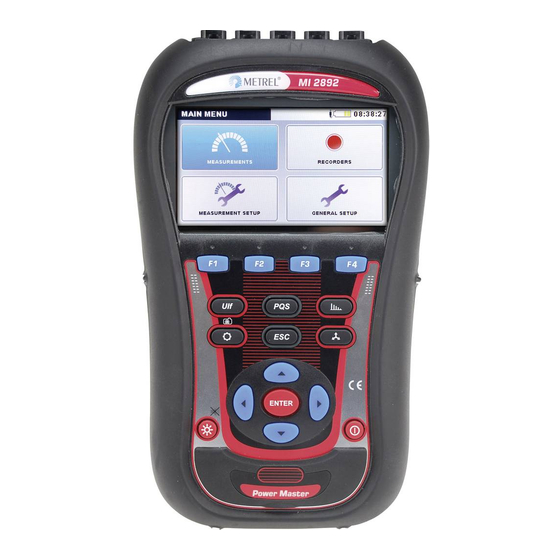
MI 2892 Power Master Introduction 1 Introduction Power Master is handheld multifunction instrument for power quality analysis and energy efficiency measurements. Figure 1.1: Power Master instrument 1.1 Main Features Full compliance with power quality standard IEC 61000-4-30 Class A. ... -
Page 8: Safety Considerations
MI 2892 Power Master Introduction Waveform/inrush recorder, which can be triggered on event or alarms, and run simultaneously with general recorder. Powerful troubleshooting tools: transient recorder with envelope and level triggering. Support for 50Hz, 60Hz, 400Hz system frequency and direct VFD (variable frequency drives) measuremend ... -
Page 9: Applicable Standards
MI 2892 Power Master Introduction Always short unused voltage inputs (L1, L2, L3, GND) with neutral (N) input to prevent measurement errors and false event triggering due to noise coupling. Do not remove microSD memory card while instrument is recording or reading data. Record damage and card failure can occur. -
Page 10: Abbreviations
MI 2892 Power Master Introduction IEC 62053-21 : 2003 Part 21: Static meters for active energy (Class 1) IEC 62053-23 : 2003 Part 23: Static meters for reactive energy (Class 2) IEEE 1459 : 2010 IEEE Standard Definitions for the Measurement of Electric Power Quantities Under Sinusoidal, Nonsinusoidal, Balanced, or Unbalanced Conditions EN 50160 : 2010... - Page 11 MI 2892 Power Master Introduction Minus sign indicates generated power DPFa totcap and plus sign indicates consumed power. Suffix ind/cap represents DPFa DPFa totcap- totind+ inductive/capacitive character. This DPFa DPFa totcap+ totind- parameter is recorded separately as shown on figure. See 5.1.6 for definition.
- Page 12 MI 2892 Power Master Introduction 1.4.3 Phase harmonics distortion power, including harmonics distortion power). See 5.1.5 section: Modern Power measurement Standard compliance: IEEE 1459-2010 for definition. Total effective harmonics distortion power. See 5.1.5 section: Total nonfundamental power measurements for definition. 1.4.4 Phase voltage distortion power, including D distortion power).
- Page 13 MI 2892 Power Master Introduction Fundamental RMS current Ih (on 1 harmonics), including Ifund Ifund (phase p fundamental RMS current) and Ifund (neutral RMS fundamental current). See 5.1.8 for definition current RMS harmonic component including I (phase p; n RMS current harmonic component) and I (neutral n RMS current harmonic component).
- Page 14 MI 2892 Power Master Introduction Instantaneous positive sequence of total active fundamental power. Minus sign indicates generated and plus sign indicates consumed power. See 5.1.5 for definitions. Recorded positive sequence of total active fundamental power. Minus sign indicates generated and plus sign indicates positive sequence of consumed power.
- Page 15 MI 2892 Power Master Introduction Recorded total arithmetic combined (fundamental and nonfundamental) power factor. Minus sign indicates generated totind totcap totind power and plus sign indicates consumed power. Suffix ind/cap totcap totcap totind represents inductive/capacitive character. This parameter is recorded separately for each quadrant as shown on figure.
- Page 16 MI 2892 Power Master Introduction Short term flicker (1 minute) including P (phase p to phase g st(1min)pg short term voltage flicker) and P (phase p to neutral voltage st(1min) st(1min)p flicker). See 5.1.10 for definition. Instantaneous flicker including P (phase p to phase g instpg instantaneous voltage flicker) and P...
- Page 17 MI 2892 Power Master Introduction Recorded phase fundamental reactive power. Suffix ind/cap represents inductive/capacitive character. Minus sign indicates generated and plus sign Qfund indicates consumed fundamental Qfund reactive power. This parameter is recorded separately for each quadrant as shown on figure. See 5.1.5 for definition.
- Page 18 MI 2892 Power Master Introduction Phase fundamental apparent power, including Sfund (phase p Sfund fundamental apparent power). See 5.1.5 for definition. Fundamental total arithmetic apparent power. See 5.1.6 for Safund definition. Svfund Fundamental total vector apparent power. See 5.1.6 for definition. Positive sequence of total fundamental apparent power.
- Page 19 MI 2892 Power Master Introduction Minimal U voltage measured during interrupt occurrence. Rms(1/2) Nominal voltage, normally a voltage by which network is designated or identified. Voltage overdeviation, difference between the measured value and the nominal value of a voltage, only when the measured value is greater than the nominal value.
-
Page 20: Description
MI 2892 Power Master Description 2 Description 2.1 Front panel Figure 2.1: Front panel Front panel layout: Colour TFT display, 4.3 inch, 480 x 272 pixels. 1. LCD Function keys. 2. F1 – F4 Moves cursor and select parameters. 3. ARROW keys Step into submenu. -
Page 21: Connector Panel
MI 2892 Power Master Description 2.2 Connector panel Warnings! Use safety test leads only! Max. permissible nominal voltage between voltage input terminals and ground is 1000 V Max. short-term voltage of external power supply adapter is 14 V! Figure 2.2: Top connector panel Top connector panel layout: Clamp-on current transformers (I ) input terminals. -
Page 22: Bottom View
MI 2892 Power Master Description 2.3 Bottom view Figure 2.4: Bottom view Bottom view layout: 1. Battery compartment cover. 2. Battery compartment screw (unscrew to replace the batteries). 3. Serial number label. 2.4 Accessories 2.4.1 Standard accessories Table 2.1: Power Master standard accessories Description Pieces Flexible current clamp 3000 A / 300 A / 30 A (A 1227) -
Page 23: Operating The Instrument
MI 2892 Power Master Operating the instrument 3 Operating the instrument This section describes how to operate the instrument. The instrument front panel consists of a colour LCD display and keypad. Measured data and instrument status are shown on the display. Basic display symbols and keys description is shown on figure below. -
Page 24: Instrument Status Bar
MI 2892 Power Master Operating the instrument 3.1 Instrument status bar Instruments status bar is placed on the top of the screen. It indicates different instrument states. Icon descriptions are shown on table below. Status bar Figure 3.3: Instrument status bar Table 3.1: Instrument status bar description Indicates battery charge level. -
Page 25: Instrument Keys
MI 2892 Power Master Operating the instrument Memory list recall. Shown screen is recalled from instrument memory. Flagged data mark. While observing recorded data this mark will indicate that observed measurement results for given time interval can be compromised due to interrupt, dip or swells occurrence. -
Page 26: Instrument Memory (Microsd Card)
MI 2892 Power Master Operating the instrument 3.3 Instrument memory (microSD card) Power master use microSD card for storing records. Prior instrument use, microSD card should be formatted to a single partition FAT32 file system and inserted into the instrument, as shown on figure below. -
Page 27: Instrument Submenus
MI 2892 Power Master Operating the instrument Figure 3.5: “MAIN MENU” Table 3.3: Instrument Main menu MEASUREMENT submenu. Provide access to various instrument measurement screens RECORDER submenu. Provide access to instrument recorders configuration and storage. MEASUREMENT SETUP submenu. Provide access to the measurement settings. GENERAL SETUP submenu. - Page 28 MI 2892 Power Master Operating the instrument Figure 3.6: Measurements submenu Figure 3.7: Recorders submenu Figure 3.8: Measurement setup submenu Figure 3.9: General setup submenu...
-
Page 29: U, I, F
MI 2892 Power Master Operating the instrument Table 3.5: Keys in submenus Selects function within each submenu. Enters selected function. ENTER Returns to the “MAIN MENU”. 3.5 U, I, f Voltage, current and frequency parameters can be observed in the “U, I, f” screens. Measurement results can be viewed in a tabular (METER) or a graphical form (SCOPE, TREND). - Page 30 MI 2892 Power Master Operating the instrument Figure 3.11: U, I, f meter summary table screens In those screens on-line voltage and current measurements are shown. Descriptions of symbols and abbreviations used in this menu are shown in table below. Table 3.6: Instrument screen symbols and abbreviations True effective value U and I...
-
Page 31: Scope
MI 2892 Power Master Operating the instrument Δ Shows measurements for all phase to phase voltages. 1 2 3 N Shows measurements for phase to phase voltage L12. Δ 23 31 Shows measurements for phase to phase voltage L23. Δ... -
Page 32: Trend
MI 2892 Power Master Operating the instrument I1, I2, I3, In True effective value of current: I Table 3.9: Keys in Scope screens HOLD Holds measurement on display. Runs held measurement. Selects which waveforms to show: Shows voltage waveform. I U,I U/I Shows current waveform. - Page 33 MI 2892 Power Master Operating the instrument Figure 3.16: Voltage trend (all voltages) Figure 3.17: Voltage trend (single voltage) Figure 3.18: Voltage and current trend (single Figure 3.19: Voltage and current trend (dual mode) mode) Figure 3.20: Trends of all currents Figure 3.21: Frequency trend Table 3.10: Instrument screen symbols and abbreviations U1, U2, U3, Un,...
-
Page 34: Power
MI 2892 Power Master Operating the instrument Current GENERAL RECORDER time 32m 00s (d - days, h - hours, m - minutes, s - seconds) Table 3.11: Keys in Trend screens Selects between the following options: Shows voltage trend. I f U,I U/I Shows current trend. - Page 35 MI 2892 Power Master Operating the instrument Figure 3.22: Power measurements summary Figure 3.23: Power measurements summary (combined) (fundamental) Figure 3.24: Detailed power measurements at Figure 3.25: Detailed total power measurements phase L1 Description of symbols and abbreviations used in POWER (METER) screens are shown in table below. Table 3.12: Instrument screen symbols and abbreviations (see 5.1.5 for details) –...
- Page 36 MI 2892 Power Master Operating the instrument In Combined column: Combined (fundamental and nonfundamental) total arithmetic apparent power (Sa In Fundamental column: Fundamental total arithmetic apparent power (Safund Depending on the screen position: In Combined column: Combined (fundamental and nonfundamental) total vector apparent power (Sv In Fundamental column: Fundamental total vector apparent power (Svfund...
-
Page 37: Trend
MI 2892 Power Master Operating the instrument Table 3.13: Keys in Power (METER) screens Holds measurement on display. Hold clock time will be displayed in the HOLD right top corner. Runs held measurement. VIEW Switches between Combined, Fundamental and Nonfundamental view. Shows measurements for phase L1. - Page 38 MI 2892 Power Master Operating the instrument View: Combined power Nc1±, Nc2±, Maximal ( ), average ( ) and minimal ( ) value of consumed (N 1cap 2cap Nc3±, Nct± ) or generated (N ) capacitive combined 3cap totcap 1cap 2cap 3cap totcap...
- Page 39 MI 2892 Power Master Operating the instrument Maximal ( ), average ( ) and minimal ( ) value of consumed or generated phase voltage distortion power (Dv , Dv , Dv , Dev ) for time interval (IP) selected by cursor. View: Nonfundamental power Ph1±, Ph2±, Ph3±, Maximal ( ), average ( ) and minimal ( ) value of consumed (P...
-
Page 40: Energy
MI 2892 Power Master Operating the instrument Shows nonfundamental current distortion power. Dv Ph Shows nonfundamental voltage distortion power. Sn Di Shows nonfundamental active power. Sn Di Dv Selects between phase, all-phases and Total power view: Shows power parameters for phase L1. 2 3 ... -
Page 41: Trend
MI 2892 Power Master Operating the instrument Table 3.17: Keys in Energy (METER) screens HOLD Holds measurement on display. Runs held measurement. Shows energy registers for whole record. LAST CUR LAST Shows energy registers for last interval. Shows energy registers for current interval. TOT LAST Shows energy parameters for phase L1. -
Page 42: Efficiency
MI 2892 Power Master Operating the instrument Table 3.19: Keys in Energy (TREND) screens Shows active consumed energy for time interval (IP) selected by Eq+ Ep- Eq- cursor. Shows reactive consumed energy for time interval (IP) selected by Ep- Eq- cursor. - Page 43 MI 2892 Power Master Operating the instrument Qi avg+ Consumed phase fundamental inductive reactive power (Qfund , Qfund ind1 ind2 Qfund Qi+ avg+ ind3 Positive sequence of total inductive fundamental consumed reactive power (Q Generated phase fundamental inductive reactive power (Qfund , Qfund , Qfund Qi avg-...
-
Page 44: Harmonics / Interharmonics
MI 2892 Power Master Operating the instrument GREEN colour – represents part of conductor cross section (wire) used for active energy transfer (Ep) RED colour – represents part of conductor cross section (wire) used for fundamental reactive energy transfer (Eq) ... - Page 45 MI 2892 Power Master Operating the instrument Figure 3.30: Harmonics and interharmonics (METER) screens Description of symbols and abbreviations used in METER screens are shown in table below. Table 3.22: Instrument screen symbols and abbreviations RMS voltage / current value Total voltage / current harmonic distortion THD and THD in % of fundamental...
-
Page 46: Histogram (Bar)
MI 2892 Power Master Operating the instrument Shows harmonics / interharmonics components for phase L1. 2 3 N Shows harmonics / interharmonics components for phase L2. 3 N Shows harmonics / interharmonics components for phase L3. N Shows harmonics / interharmonics components for neutral channel. - Page 47 MI 2892 Power Master Operating the instrument Ix h01 … h50 Instantaneous current harmonic / interharmonic component in A and in % of fundamental current Ux DC Instantaneous DC voltage in V and in % of fundamental voltage Ix DC Instantaneous DC current in A and in % of fundamental current Ux THD Instantaneous total voltage harmonic distortion THD...
-
Page 48: Harmonics Average Histogram (Avg Bar)
MI 2892 Power Master Operating the instrument Returns to the “MEASUREMENTS” submenu. 3.8.3 Harmonics Average Histogram (Avg Bar) During active GENERAL RECORDER, Harmonics average histogram AVG view is available (see section 3.14 for instructions how to start GENERAL RECORDER). In this view average voltage and current harmonic values are shown (averaged from beginning of the recording to the current moment). -
Page 49: Trend
MI 2892 Power Master Operating the instrument Selects between single phases and neutral channel harmonics / interharmonics bars. Shows harmonics / interharmonics components for phase L1. 2 3 N Shows harmonics / interharmonics components for phase L2. Shows harmonics / interharmonics components for phase L3. Shows harmonics / interharmonics components for neutral channel. - Page 50 MI 2892 Power Master Operating the instrument Figure 3.33: Harmonics and interharmonics trend screen Table 3.28: Instrument screen symbols and abbreviations ThdU Interval maximal ( ) and average ( ) value of total voltage harmonic distortion for selected phase ThdI Interval maximal ( ) and average ( ) value of total current harmonic distortion for selected phase Interval maximal ( ) and average ( ) value of DC voltage component for selected...
-
Page 51: Flickers
MI 2892 Power Master Operating the instrument Selects between single phases and neutral channel harmonics / interharmonics trends. Shows selected harmonics / interharmonics components for phase L1. 2 3 N Shows selected harmonics / interharmonics components for phase L2. Shows selected harmonics / interharmonics components for phase L3. Shows selected harmonics / interharmonics components for neutral 1 2 3 channel. -
Page 52: Trend
MI 2892 Power Master Operating the instrument Figure 3.34: Flickers table screen Description of symbols and abbreviations used in METER screen is shown in table below. Note that Flickers measurement intervals are synchronised to real time clock, and therefore refreshed on minute, 10 minutes and 2 hours intervals. - Page 53 MI 2892 Power Master Operating the instrument Table 3.32: Instrument screen symbols and abbreviations Pst1m1, Pst1m2, Pst1m3, Maximal ( ), average ( ) and minimal ( ) value of 1-minute short term flicker for phase voltages U or line voltages U Pst1m12, st(1min) Pst1m23,...
-
Page 54: Phase Diagram
MI 2892 Power Master Operating the instrument 3.10 Phase Diagram Phase diagram graphically represent fundamental voltages, currents and phase angles of the network. This view is strongly recommended for checking instrument connection before measurement. Note that most measurement issues arise from wrongly connected instrument (see 4.1 for recommended measuring practice). -
Page 55: Unbalance Diagram
MI 2892 Power Master Operating the instrument Triggers Waveform snapshot. Returns to the “MEASUREMENTS” submenu. 3.10.2 Unbalance diagram Unbalance diagram represents current and voltage unbalance of the measuring system. Unbalance arises when RMS values or phase angles between consecutive phases are not equal. Diagram is shown on figure below. -
Page 56: Unbalance Trend
MI 2892 Power Master Operating the instrument Table 3.37: Keys in Unbalance diagram screens Holds measurement on display. Hold clock time will be displayed in the HOLD right top corner. Runs held measurement. Shows voltage unbalance measurement and selects voltage for scaling (with cursors) Shows current unbalance measurement and selects current for scaling (with cursors) -
Page 57: Temperature
MI 2892 Power Master Operating the instrument Maximal ( ), average ( ) and minimal ( ) value of negative sequence current I Maximal ( ), average ( ) and minimal ( ) value of zero sequence current I Table 3.39: Keys in Unbalance trend screens U+ U- U0 Shows selected voltage and current unbalance measurement (U I+ I- I0... -
Page 58: Trend
MI 2892 Power Master Operating the instrument TREND Switches to TREND view (available only during recording). Triggers Waveform snapshot. Returns to the “MEASUREMENTS” submenu. 3.11.2 Trend Temperature measurement TREND can be viewed during the recording in progress. Records containing temperature measurement can be viewed from Memory list and by using PC software PowerView v3.0. Figure 3.40: Temperature trend screen Table 3.42: Instrument screen symbols and abbreviations Maximal ( ), average ( ) and minimal ( ) temperature value for last recorded... -
Page 59: Trend
MI 2892 Power Master Operating the instrument Figure 3.41: Underdeviation and overdeviation table screen Description of symbols and abbreviations used in METER screen is shown in table below. Table 3.44: Instrument screen symbols and abbreviations Urms True effective value U Uunder Instantaneous underdeviation voltage U expressed in voltage and % of nominal... - Page 60 MI 2892 Power Master Operating the instrument Figure 3.42: Underdeviation and overdeviation TREND screen Table 3.46: Instrument screen symbols and abbreviations Uunder1 Uunder2 Uunder3 Interval average ( ) value of corresponding underdeviation voltage U 1Under Uunder12 , expressed in % of nominal voltage. 2Under 3Under 12Under...
-
Page 61: Signalling
MI 2892 Power Master Operating the instrument 3.13 Signalling Mains signalling voltage, called “ripple control signal” in certain applications, is a burst of signals, often applied at a non-harmonic frequency, that remotely control industrial equipment, revenue meters, and other devices. Before observing signalling measurements, user should set-up signalling frequencies in signalling setup menu (see section 3.21.4). -
Page 62: Trend
MI 2892 Power Master Operating the instrument Triggers Waveform snapshot. Returns to the “MEASUREMENTS” submenu. 3.13.2 Trend During active recording TREND view is available (see section 3.14 for instructions how to start recording). Signalling parameters can be observed by cycling function key F4 (METER -TREND). Figure 3.44: Signalling trend screen Table 3.50: Instrument screen symbols and abbreviations Maximal ( ), average ( ) and minimal ( ) value of (U... -
Page 63: Table
MI 2892 Power Master Operating the instrument TREND Switches to TREND view (available only during recording). TABLE Switches to TABLE view (available only during recording). Moves cursor and select time interval (IP) for observation. Returns to the “MEASUREMENTS” submenu. 3.13.3 Table During active recording TABLE view is available (see section 3.14 for instructions how to start recording), by cycling function key F4 (METER –TREND - TABLE). -
Page 64: General Recorder
MI 2892 Power Master Operating the instrument Table 3.53: Keys in Signalling (TABLE) screen METER Switches to METER view. TREND Switches to TREND view (available only during recording). TABLE Switches to TABLE view (available only during recording). Moves cursor through signalling table. Returns to the “MEASUREMENTS”... - Page 65 MI 2892 Power Master Operating the instrument Note: If during record session instrument batteries are drained, due to long interruption for example, instrument will shut down automatically. After power restauration, it will automatically start new recording session. Include Voltage events (with waveform) or Include Alarms (with waveform) option is selected.
-
Page 66: Waveform/Inrush Recorder
MI 2892 Power Master Operating the instrument Table 3.55: Keys in General recorder setup screen START Starts the recorder. Stops the recorder. STOP Show help screen where it’s explained which measurements will be recoded with Limited and Standard profile. HELP See section 4.4 for details. -
Page 67: Setup
MI 2892 Power Master Operating the instrument Record Post-trigger Pre-trigger Record stop Record start Trigger point Figure 3.47: Triggering in waveform record 3.15.1 Setup By entering WAVEFORM RECORDER from the RECORDERS submenu the following setup screen is shown: Figure 3.48: Waveform recorder setup screen Table 3.56: Waveform recorder settings description and screen symbols Waveform recorder is active, waiting for trigger Waveform recorder is active, recording in progress... - Page 68 MI 2892 Power Master Operating the instrument Continuous (Max. 200 record)– consecutive waveform recording until user stops the measurement or instrument runs out of storage memory. Every consecutive waveform recording will be treated as a separate record. By default, maximal 200 records can be recorded.
-
Page 69: Capturing Waveform
MI 2892 Power Master Operating the instrument CONFIG Shortcut to CONNECTION SETUP menu. See 3.21.1 for details. Show last captured waveform record from MEMORY LIST. LAST REC SCOPE Switches to SCOPE view. (Active only if recording in progress). Check connection settings. See 3.21.1 for details. CHECK C. -
Page 70: Captured Waveform
MI 2892 Power Master Operating the instrument Table 3.58: Instrument screen symbols and abbreviations Waveform recorder is active, waiting for trigger Waveform recorder is active, recording in progress U1, U2, U3, Un True effective value of phase voltage: U 1Rms 2Rms 3Rms NRms... - Page 71 MI 2892 Power Master Operating the instrument Figure 3.50: Captured waveform recorder screen Table 3.60: Instrument screen symbols and abbreviations Memory list recall. Shown screen is recalled from memory Cursor position in seconds (regarding to trigger time – blue line on graph) u1(t), u2(t), u3(t), un(t) Samples value of phase voltages U...
-
Page 72: Transient Recorder
MI 2892 Power Master Operating the instrument Moves cursor. Toggles between sample value and true effective half cycle value at cursor position. ENTER Toggles cursor between voltage and current (only in U,I or U/I). Returns to the “MEMORY LIST” submenu. 3.16 Transient recorder Transient is a term for short, highly damped momentary voltage or current disturbance. -
Page 73: Capturing Transients
MI 2892 Power Master Operating the instrument In: Trigger on transients at Neutral current channel Level Trigger level in voltage/current Duration Record length in periods of fundamental frequency Pretrigger Recorded intervals before triggering occur. Store mode setup: Single – transient recording ends after first trigger ... - Page 74 MI 2892 Power Master Operating the instrument Figure 3.52: Transient recorder capture screen Table 3.64: Instrument screen symbols and abbreviations Transient recorder is active, waiting for trigger Transient recorder is active, recording in progress U1, U2, U3, Un True 1-cycle effective value of phase voltage: U 1Rms 2Rms 3Rms...
-
Page 75: Captured Transients
MI 2892 Power Master Operating the instrument Returns to the “TRANSIENT RECORDER” setup screen. 3.16.3 Captured transients Captured transient records can be viewed from the Memory list where captured waveforms can be analysed. Trigger occurrence is marked with the blue line, while cursor position line is marked in black. Figure 3.53: Captured transient recorder screen Table 3.66: Instrument screen symbols and abbreviations Memory list recall. -
Page 76: Events Table
MI 2892 Power Master Operating the instrument ZOOM Sets horizontal zoom Sets vertical zoom. Moves cursor. Toggles cursor between voltage and current (only in U,I or U/I). ENTER Returns to the “MEMORY LIST” submenu. 3.17 Events table In this table captured voltage dips, swells and interrupts are shown. Note that events appear in the table after finishing, when voltage return to the normal value. - Page 77 MI 2892 Power Master Operating the instrument Figure 3.55: Voltage event in detail view screen Table 3.68: Instrument screen symbols and abbreviations Date Date when selected event has occurred Unified event number (ID) Indicate phase or phase-to-phase voltage where event has occurred: 1 –...
- Page 78 MI 2892 Power Master Operating the instrument Shows poly-phase voltage interrupts only, according to the IEC 61000-4- 30 requirements. START time and Duration in table is referenced to voltage interrupt only. Shows event statistics (by phases). STAT EVENTS Returns to “EVENTS” view. Selects event.
- Page 79 MI 2892 Power Master Operating the instrument event number, event start time, duration and level. Additionally in colon “T” type of event is shown (see table below for details). Figure 3.56: Voltage events screens You can also see details of each individual voltage event and statistics of all events. Statistics show count registers for each individual event type by phase.
-
Page 80: Alarms Table
MI 2892 Power Master Operating the instrument SWELL Shows swells only. DIP INT Filters events by phase: Shows only events on phase L1. 2 3 T Shows only events on phase L2. Shows only events on phase L3. Shows events on all phases. 1 2 3 Shows only events on phases L12. - Page 81 MI 2892 Power Master Operating the instrument Table 3.72: Instrument screen symbols and abbreviations Date Date when selected alarm has occurred Start Selected alarm start time (when first U value cross threshold) Indicate phase or phase-to-phase voltage where event has occurred: 1 –...
-
Page 82: Rapid Voltage Changes (Rvc) Table
MI 2892 Power Master Operating the instrument N 12 23 31 T Shows only alarms on phase L3. 1 2 3 12 23 31 T Shows only alarms on neutral channel. Shows only alarms on phases L12. 1 2 3 N 23 31 T ... -
Page 83: Memory List
MI 2892 Power Master Operating the instrument dMax ∆Umax - maximum absolute difference between any of the U Rms(1/2) values during the RVC event and the final arithmetic mean 100/120 U value just Rms(1/2) prior to the RVC event. dUss ∆Uss - is the absolute difference between the final arithmetic mean 100/120 U value just prior to the RVC event and the first arithmetic mean... - Page 84 MI 2892 Power Master Operating the instrument Table 3.76: Instrument screen symbols and abbreviations Record No Selected record number, for which details are shown / Number of all records. Record name on SD Card. By convention file names are created by following rules: Rxxxxyyy.REC, where: ...
-
Page 85: General Record
MI 2892 Power Master Operating the instrument 3.20.1 General Record This type of record is made by GENERAL RECORDER. Record front page is similar to the GENERAL RECORDER setup screen, as shown on figure below. Figure 3.60: Front page of General record in MEMORY LIST menu Table 3.78: Recorder settings description Record No. - Page 86 MI 2892 Power Master Operating the instrument Enters particular signal group (TREND view). ENTER Exits to MEMORY LIST menu. CLEAR Clears the last record. In order to clear complete memory, delete records one by one. Opens confirmation window for clearing all saved records. Keys in confirmation window: Selects YES or NO.
-
Page 87: Waveform Snapshot
MI 2892 Power Master Operating the instrument Maximal ( ), average ( ) and minimal ( ) recorded value of current I 1Rms 2Rms , for time interval selected by cursor. 3Rms NRms 38m 00s Time position of cursor regarding to the record start time. 10.May.2013 Time clock at cursor position. - Page 88 MI 2892 Power Master Operating the instrument Figure 3.62: Front page of Snapshot in MEMORY LIST menu Table 3.82: Recorder settings description Record No. Selected record number, for which details are shown. FILE NAME Record name on SD Card Indicate type of record: Type ...
-
Page 89: Waveform/Inrush Record
MI 2892 Power Master Operating the instrument Selects YES or NO. Confirms selection. ENTER Exits confirmation window without clearing saved records. Browses through records (next or previous record). Returns to the “RECORDERS” submenu. By pressing VIEW in CHANNELS SETUP menu METER screen will appear. Typical screen is shown on figure below. -
Page 90: Connection Setup
MI 2892 Power Master Operating the instrument Figure 3.64: MEASUREMENT SETUP submenu Table 3.84: Description of Measurement setup options Connection setup Setup measurement parameters. Event setup Setup event parameters. Alarm setup Setup alarm parameters. Signalling setup Setup signalling parameters. Table 3.85: Keys in Measurement setup submenu screen Selects option from the “MEASUREMENT SETUP”... - Page 91 MI 2892 Power Master Operating the instrument Figure 3.65: “CONNECTION SETUP” screen Table 3.86: Description of Connection setup Set nominal voltage. Select voltage according to the network voltage. If voltage is measured over potential transformer then press ENTER for setting transformer parameters: Nominal voltage Voltage ratio: Potential transformer ratio Δ...
- Page 92 MI 2892 Power Master Operating the instrument Note: For Smart clamps (A 1227, A 1281) always select “Smart clamps”. Note: Use “None" option for voltage measurements only. Note: See section 4.2.3 for details regarding further clamps settings. Method of connecting the instrument to multi-phase systems (see 4.2.1 for details).
- Page 93 MI 2892 Power Master Operating the instrument OpenD: 3-phase 2 -wire (Open Delta) system. Synchronization channel. This channel is used for instrument synchronization to the network frequency. Also a frequency measurement is performed on that channel. Depending on Synchronization Connection user can select: ...
- Page 94 MI 2892 Power Master Operating the instrument Check if measurement results comply with given limits. Connection check is marked with green OK sign ( ) if instrument is connected properly and measurement comply with given measurement setup. Connection check is marked with yellow OK sign ( ), indicate that some measurement are at the edge of instrument technical specification.
-
Page 95: Event Setup
MI 2892 Power Master Operating the instrument Table 3.87: Keys in Connection setup menu Selects Connection setup parameter to be modified. Changes selected parameter value. Enters into submenu. ENTER Confirms Factory reset. Depends from Connection check status. For: OK sign ( , ) Returns to the “MEASUREMENT SETUP”... - Page 96 MI 2892 Power Master Operating the instrument Keys in CHANNELS SETUP menu screen: PREV Previous help screen NEXT Next help screen Move between help screens. ENTER Move back to EVENT SETUP screen Selects Voltage events setup paramet...
-
Page 97: Alarm Setup
MI 2892 Power Master Operating the instrument er to be modifie Changes selected parameter value. Returns to the “MEASUREMENT SETUP” submenu. 3.21.3 Alarm setup Up to 10 different alarms, based on any measurement quantity which is measured by instrument, can be defined. -
Page 98: Signalling Setup
MI 2892 Power Master Operating the instrument column - Minimal alarm duration. Triggers only if threshold is crossed for a defined period of time. Du–ation Note: It is recommended that for flicker measurement, recorder is set to 10 min. Table 3.91: Keys in Alarm setup screens Adds new alarm. -
Page 99: Rapid Voltage Changes (Rvc) Setup
MI 2892 Power Master Operating the instrument SIGN. 2 FREQUENCY observed signalling frequency. DURATION Duration of RMS record, which will be captured after treshold value is reached. THRESHOLD Threshold value expressed in % of nominal voltage, which will trigger recording of signalling event. Table 3.93: Keys in Signalling setup screen Enters or exits a submenu to set signalling frequency. -
Page 100: Measuring Methods Setup
MI 2892 Power Master Operating the instrument Changes selected parameter. Returns to the “MEASUREMENT SETUP” submenu. 3.21.6 Measuring Methods setup In this menu diferent measurement methds can be selected, according to the local standards and practice. See section 5.1.5 for Modern Power measurement and 5.1.6 for Classic Vector and Arithmetic Power measurement details. -
Page 101: Communication
INTERNET (3G, GPRS). Instrument is connected to the internet over 3G or GPRS modem. This option minimise internet 3G traffic with Metrel GPRS Relay server and PowerView, in order to reduce link cost. Instrument in idle state (while not connected to the PowerView) consume... - Page 102 MI 2892 Power Master Operating the instrument Figure 3.72: Communication setup screen Table 3.100: Description of Communication setup options Select USB or INTERNET, INTERNET (3G / GPRS), INTRANET (LAN) PC connection communication port. Select GPS or MI 3108 / MI 3109 communication. GPS is used for A Com Port (PS/2) 1355 GPS receiver, and MI 3108 / MI 3109 for photovoltaics inverter measurements (See MI 3108/ MI 3109 User manual).
-
Page 103: Time & Date
MI 2892 Power Master Operating the instrument Enters Secret key edit window. ENTER Returns to the “GENERAL SETUP” submenu. 3.22.2 Time & Date Time, date and time zone can be set in this menu. 3.22.3 Time & Date Figure 3.73: Set date/time screen Table 3.102: Description of Set date/time screen Show clock source: RTC –... -
Page 104: Language
MI 2892 Power Master Operating the instrument Table 3.103: Keys in Set date/time screen Selects parameter to be changed. Modifies parameter. Selects between the following parameters: hour, minute, second, day, month or year. Enters Date/time edit window. ENTER Returns to the “GENERAL SETUP” submenu. 3.22.4 Language Different languages can be selected in this menu. -
Page 105: Lock/Unlock
MI 2892 Power Master Operating the instrument Figure 3.75: Instrument info screen Table 3.105: Keys in Instrument info screen Returns to the “GENERAL SETUP” submenu. 3.22.6 Lock/Unlock Power Master has the ability to prevent unauthorized access to all important instrument functionality by simply locking the instrument. -
Page 106: Colour Model
MI 2892 Power Master Operating the instrument Table 3.107: Keys in Lock/Unlock screen Selects parameter to be modified. Change value of the selected digit in Enter pin window. Selects digit in Enter pin window. Locks the instrument. Opens Enter pin window for unlocking. Opens Enter pin window for pin modification. - Page 107 MI 2892 Power Master Operating the instrument Figure 3.78: Colour representation of phase voltages Table 3.109: Keys in Colour model screens Opens edit colour screen (only available in custom model). EDIT Keys in Edit colour screen: Shows selected colour for phase L1. L2 L3 N Shows selected colour for phase L2.
-
Page 108: Recording Practice And Instrument Connection
MI 2892 Power Master Recording Practice and Instrument Connection 4 Recording Practice and Instrument Connection In following section recommended measurement and recording practice is described. 4.1 Measurement campaign Power quality measurements are specific type of measurements, which can last many days, and mostly they are performed only once. - Page 109 MI 2892 Power Master Recording Practice and Instrument Connection Start Prepare instrument for new measurement, before going to measuring site. Check: Is it time and date correct? Step 1: Are batteries in good condition? Instrument Setup Is it Memory List empty? If it is not, ...
- Page 110 MI 2892 Power Master Recording Practice and Instrument Connection Step 1: Instrument setup On site measurements can be very stressful, and therefore it is good practice to prepare measurement equipment in an office. Preparation of Power Master include following steps: ...
- Page 111 MI 2892 Power Master Recording Practice and Instrument Connection Step 2.5: Alarm setup Use this step if you would like only to check if some quantities cross some predefined boundaries (see sections 3.18 and 3.21.3 for details). Note: You can also trigger WAVEFORM RECORDER on alarms. Instrument will then capture waveform and inrush for each alarm.
-
Page 112: Connection Setup
MI 2892 Power Master Recording Practice and Instrument Connection Note: If during record session instrument batteries are drained, due to long interruption for example, instrument will shut down. After electricity comes back, instrument will automatically start new recording session. Step 6: Measurement conclusion Before leaving measurement site we need to: ... - Page 113 MI 2892 Power Master Recording Practice and Instrument Connection 3-phase 4-wire system In order to select this connection scheme, choose following connection on the instrument: Figure 4.3: Choosing 3-phase 4-wire system on instrument Instrument should be connected to the network according to figure below: Figure 4.4: 3-phase 4-wire system 3-phase 3-wire system In order to select this connection scheme, choose following connection on the instrument:...
- Page 114 MI 2892 Power Master Recording Practice and Instrument Connection Figure 4.6: 3-phase 3-wire system Open Delta (Aaron) 3-wire system In order to select this connection scheme, choose following connection on the instrument: Figure 4.7: Choosing Open Delta (Aaron) 3-wire system on instrument Instrument should be connected to the network according to figure below.
- Page 115 MI 2892 Power Master Recording Practice and Instrument Connection 1-phase 3-wire system In order to select this connection scheme, choose following connection on the instrument: Figure 4.9: Choosing 1-phase 3-wire system on instrument Instrument should be connected to the network according to figure below. Figure 4.10: 1-phase 3-wire system Note: In case of events capturing, it is recommended to connect unused voltage terminals to N voltage terminal.
-
Page 116: Connection To The Mv Or Hv Power System
MI 2892 Power Master Recording Practice and Instrument Connection Figure 4.11: Choosing 2-phase 4-wire system on instrument Instrument should be connected to the network according to figure below. Figure 4.12: 2-phase 4-wire system Note: In case of events capturing, it is recommended to connect unused voltage terminal to N voltage terminal. - Page 117 MI 2892 Power Master Recording Practice and Instrument Connection Figure 4.13: Voltage ratio for 11 kV / 110 kV transformer example Instrument should be connected to the network according to figure below. power plant measuring instruments high voltage Transformer Type: xA / 5A xA / 5A xA / 5A...
- Page 118 MI 2892 Power Master Recording Practice and Instrument Connection power plant measuring instruments high voltage Transformer Type: xA / 5A xA / 5A xA / 5A Δ Measurement Settings Connection setup Nominal Voltage Figure 4.15: Connecting instrument to the existing current transformers in medium voltage system (Delta –...
- Page 119 MI 2892 Power Master Recording Practice and Instrument Connection power plant measuring instruments high voltage xA / 5A xA / 5A xA / 5A Δ Measurement Settings Connection setup Nominal Voltage Figure 4.16: Connecting instrument to the existing current transformers in medium voltage system (Delta –...
- Page 120 MI 2892 Power Master Recording Practice and Instrument Connection power plant measuring instruments high voltage xA / 5A xA / 5A xA / 5A Δ Measurement Settings Connection setup Nominal Voltage Figure 4.17: Connecting instrument to the existing current transformers in medium voltage system (Star –...
-
Page 121: Current Clamp Selection And Transformation Ratio Setting
Direct current measurement can be performed by any clamp-on current transformer. We particularly recommend Smart clamps: flex clamps A1227 and iron clamps A1281. Also other Metrel clamp models A1033 (1000 A), A1069 (100 A), A1120 (3000 A), A1099 (3000 A), etc. can be used. - Page 122 MI 2892 Power Master Recording Practice and Instrument Connection 2700A parallel load feeding 900 A Load 900 A 900 A Current clamps: A1033 (1000A/1V) Clamp Selected: A 1033 Clamp Range: 1000 A Current transformer: Primary current: 1A Secondary Current: 3A Instrument display: Irms = 2700 A Figure 4.19: Parallel feeding of large load...
- Page 123 MI 2892 Power Master Recording Practice and Instrument Connection 100A load feeding 100 A Load Current Transformer: Current clamps: 600A : 5A A1122 (5A/1V) Clamp Selected: A 1122 Clamp Range: 5 A Measuring range: 100% Current transformer: Prim: 100 A Sec: 5 A Instrument display: Irms = 100 A...
- Page 124 Recording Practice and Instrument Connection Automatic current clamps recognition Metrel developed Smart current clamps product family in order to simplify current clamps selection and settings. Smart clamps are multi-range switch-less current clamps automatically recognized by instrument. In order to activate smart clamp recognition, the following procedure should be followed for the first time: 1.
-
Page 125: Connection Check
MI 2892 Power Master Recording Practice and Instrument Connection Clamps Status menu indicates that there is an inconsistence between current clamps defined in Clamps Setup menu and clamps present at the moment. Note: Do not disconnect smart clamps during recording. 4.2.4 Connection check Connection check menu in CONNECTION SETUP check if instrument measurement comply with instrument setup and connection. - Page 126 MI 2892 Power Master Recording Practice and Instrument Connection Table 4.2: Connection check description and screen symbols Measure Description Action to resolve issue Status ment Measured voltage is within 90% ÷ 110% range. All voltage measurements (RMS, harmonics, voltage events) are valid. Measured voltage is not within 90% ÷...
-
Page 127: Temperature Probe Connection
MI 2892 Power Master Recording Practice and Instrument Connection Current sequence is correct, but phase This is valid situation if there are angle between currents is more than 120 large inductive/capacitive load in ± 60 the network. However this can be also caused improper... -
Page 128: Gps Time Synchronization Device Connection
MI 2892 Power Master Recording Practice and Instrument Connection 2. Connect temperature probe to Power Master neutral current input terminal 3. Enter: Measurement setup Connection setup Phase/Neutral curr. clamps 4. Select: Smart clamps 5. Temperature probe should be now automatically recognized by the instrument Instrument will remember settings for the next time. -
Page 129: Printing Support
MI 2892 Power Master Recording Practice and Instrument Connection For detailed information please check user manual of A 1355 GPS Receiver. 4.2.1 Printing support Power Master support direct printing to Seiko DPU 414 printer. User can print any screen under MEASUREMENTS menu. -
Page 130: Remote Instrument Connection (Over Internet / 3G,Gprs)
Metrel server can be established (Status bar icon should appear within 2 minutes). Note: Outgoing ports 80, 443, 7781 ÷ 8888 to the gprs.metrel.si server should be opened on remote firewall where instrument is placed! 2. User enters instrument serial number on PowerView and connects to the instrument over Metrel server. -
Page 131: Instrument Setup On Remote Measurement Site
MI 2892 Power Master Recording Practice and Instrument Connection Router Outgoing ports 7781÷8888 to gprs.metrel.si should be open Internet Metrel Server gprs.metrel.si Outgoing ports 433 Office Router (https) and 80 (http) to server gprs.metrel.si should be open PowerView Figure 4.27: Schematic view on the remote measurements 4.3.2 Instrument setup on remote measurement site... -
Page 132: Powerview Setup For Instrument Remote Access
DHCP Server. It can take up to 2 minutes in order to get new IP number. Once instrument IP address is obtained, it will try to connect to Metrel server, over which communication with PowerView is assured. Once everything is connected, icon will appear on the Status bar. -
Page 133: Remote Connection
MI 2892 Power Master Recording Practice and Instrument Connection Figure 4.29: PowerView v3.0 remote connection settings form User need to fill following data into form: Table 4.9: Instrument selection form parameters Serial Number: Required Enter Power Master serial number Phone Number: Not Required Leave this field empty Enter number code which was entered in... - Page 134 PowerView v3.0 http access to the internet. Step 2: PowerView v3.0 connection to Metrel Server After establishing internet connection in Step 1, PowerView v3.0 will contact Metrel Server. If connection was successful, a green icon and “CONNECTED” status will appear between “Metrel Server”...
- Page 135 After the PowerView v3.0 successful connects to the Metrel Server, server will check if your instrument is waiting for your connection. If that is a case, instrument will establish connection with Metrel server. The green icon and “CONNECTED” status will appear between “Metrel Server” and “Remote...
- Page 136 After first three steps were successfully finished, Power Mater instrument will automatically connect to the PowerView v3.0 via VPN connection, made through Metrel server and establish connection. If Remote Instrument connection to PowerView v3.0 was successful, a green icon and “CONNECTED”...
- Page 137 MI 2892 Power Master Recording Practice and Instrument Connection Figure 4.33: Remote instrument connection to PowerView v3.0 established (Step 4) While the data is refreshed, the Remote button is displayed in green, to indicate that the connection is active, as shown below. If it is displayed in orange colour, it means that the communication was broken and it should be reinitialized by user.
- Page 138 MI 2892 Power Master Recording Practice and Instrument Connection Figure 4.35: Remote connection icon Downloading data If remote connection settings are correct and “Remote Instrument” is connected to PowerView v3.0, download data is possible. Open the download window by pressing F5, or by clicking on the button in the toolbar, or by selecting Download from Tools menu.
- Page 139 MI 2892 Power Master Recording Practice and Instrument Connection Figure 4.37: Downloading a list of records When the instrument model is detected, PowerView v3.0 will download a list of records from the instrument. Any of the records from the list can be selected by simply clicking on them. Additional, “Select/Deselect all”...
- Page 140 A backup PowerView v3.0 file is always created at this point, compressed into a *.zip file and saved inside your MyDocuments/Metrel/PowerView/PQData folder. This backup copy is made every time a file is created or opened, to make sure that you can recover all your downloaded data in case of accidental delete or change.
- Page 141 MI 2892 Power Master Recording Practice and Instrument Connection Figure 4.39: Real time scope window in remote connection, with several channels selected The figure above shows an online window, with several channels selected. While online view is active, data are automatically updated. Updating speed will depend on your connection speed, and each new update is initiated as soon as the previous one has been downloaded, to ensure fastest possible refresh rate.
- Page 142 MI 2892 Power Master Recording Practice and Instrument Connection Figure 4.40: Remote Instrument Configuration form Please click on the “Read” button in order to receive current instrument settings. After retrieving data from the remote instrument, form should be filled with data, as shown on figure below. Changed parameters, will be sent back to the instrument by clicking on the “Write”...
- Page 143 MI 2892 Power Master Recording Practice and Instrument Connection Figure 4.41: Remote Recorder configuration By clicking on “Start” button, instrument will start selected recorder in the same manner as would user start recorder directly on instrument. Green icon indicates that Recorder is active, while red icon indicates that recorder is stopped.
- Page 144 MI 2892 Power Master Recording Practice and Instrument Connection Figure 4.42: Recording in progress...
-
Page 145: Number Of Measured Parameters And Connection Type Relationship
MI 2892 Power Master Recording Practice and Instrument Connection 4.4 Number of measured parameters and connection type relationship Parameters which Power Master Displays and measures, mainly depends on network type, defined in CONNECTION SETUP menu – Connection type. In example if user choose single phase connection system, only measurements relate to single phase system will be present. - Page 146 MI 2892 Power Master Recording Practice and Instrument Connection In the similar manner recording quantities are related to connection type too. Recording Signals in GENERAL RECORDER menu are chosen according to the Connection type, and record PROFILE in according to the next table. Table 4.11: Quantities recorded by instrument (Standard Profile) Connection type Menu...
- Page 147 MI 2892 Power Master Recording Practice and Instrument Connection Active Energy Reactive Ener. Power factors Legend: - Quantity included. - Maximal value for each interval is recorded. - RMS or arithmetic average for each interval is recorded (see 5.1.15 for details). - Minimal value for each interval is recorded.
- Page 148 MI 2892 Power Master Recording Practice and Instrument Connection Table 4.12: Quantities recorded by instrument (Limited Profile) Connection type Menu OpenD Crest Factor Frequency Harmonics (0÷25) Interharm. (0÷25) Unbalance Flicker Signalling ...
-
Page 149: Theory And Internal Operation
MI 2892 Power Master Theory and internal operation - RMS or arithmetic average for each interval is recorded (see 5.1.15 for details). - Minimal value for each interval is recorded. - Active RMS or arithmetic average (AvgON) for each interval is recorded (see 5.1.15 for details). 5 Theory and internal operation This section contains basic theory of measuring functions and technical information of the internal operation of the Power Master instrument, including descriptions of measuring methods and logging... -
Page 150: Current Measurement (Magnitude Of Supply Current)
MI 2892 Power Master Theory and internal operation Phase voltage: [V], p: 1,2,3,N Line voltage: [V], pg.: 12,23,31 CF Phase voltage crest factor: , p: 1,2,3,N pgPk Line voltage crest factor: , pg: 12, 23, 31 The instrument has internally 3 voltage measurement ranges, which are automatically selected regarding to the nominal voltage. -
Page 151: Modern Power Measurement
MI 2892 Power Master Theory and internal operation Frequency measurement is performed on chosen Synchronization channel, in CONNECTION SETUP menu. 5.1.5 Modern Power measurement Standard compliance: IEEE 1459-2010 See section 3.21.6 how to select Modern Power measurement method. Please note that instrument record all measurement (Classic and Modern), regardless of selected method. - Page 152 MI 2892 Power Master Theory and internal operation fund fund fund (positive sequence of (positive sequence of (effective fundamental fundamental active power) fundamental apparent power) apparent power) (effective apparent fund power) (unbalanced fundamental (positive sequence of apparent power) fundamental reactive power) (effective non fundamental apparent power) (effective current distortion power)
- Page 153 MI 2892 Power Master Theory and internal operation [var], p: 1,2,3 Sign PF Phase power factor: , p: 1,2,3 (10) Total combined power measurements Standard compliance: IEEE STD 1459-2010 Total combined (fundamental + nonfundamental) active, nonactive and apparent power and total power factor are calculated according to the following equation: ...
- Page 154 MI 2892 Power Master Theory and internal operation -DPF +DPF +DPF -DPF Fundamental phase reactive power: (19) [var], p: 1,2,3 fundP fundP fundP Phase displacement power factor: (20) , p: 1,2,3 Positive sequence (total) fundamental power measurements Standard compliance: IEEE STD 1459-2010 According to the IEEE STD 1459, positive sequence power (P ) are recognised as very important...
- Page 155 MI 2892 Power Master Theory and internal operation Nonfundamental power measurements are measured according to following equations: Phase nonfundamental apparent power: (25) [VA], p: 1,2,3 Phase current distortion power (26) [VA], p: 1,2,3 fundP Phase voltage distortion power: (27) ...
-
Page 156: Classic Vector And Arithmetic Power Measurement
MI 2892 Power Master Theory and internal operation where: fund fund fund Total effective distortion power (36) [var] Harmonic pollution (37) fund where: 3 fund fund fund Load unbalance (38) ... - Page 157 MI 2892 Power Master Theory and internal operation In table below summary of all power measurement is shown. Table 5.3: Summary and grouping of the phase power quantities Quantity Combined Fundamental powers powers Apparent (VA) fund Active (W) fund Nonactive/reactive (var) fund Line utilization ind/cap...
- Page 158 MI 2892 Power Master Theory and internal operation Total active power: [W], (43) Total apparent power (arithmetic): [VA], (44) (45) Total nonactive power (arithmetic): [var], PFa Total power factor (arithmetic): (46) Fundamental phase power measurements Standard compliance: IEEE STD 1459-2010 All Classic fundamental phase power measurements are identical with Modern fundamental phase...
-
Page 159: Energy
MI 2892 Power Master Theory and internal operation (53) Total nonactive power (arithmetic): [var], fundtot fundtot fundtot DPFa fundtot Total power factor (arithmetic): (54) fundtot All fundamental power measurements are calculated from fundamental voltages and currents obtained from harmonic analysis (see section 5.1.8 for details). -
Page 160: Harmonics And Interharmonics
MI 2892 Power Master Theory and internal operation Instrument has 3 different counters sets: 1. Total counters are used for measuring energy over a complete recording. When recorder starts it sums the energy to existent state of the counters. 2. Last integration period LAST counter measures energy during recording over last completed interval. - Page 161 MI 2892 Power Master Theory and internal operation 1024 (57) – frequency of signal fundamental (in example: 50 Hz) – DC component k – ordinal number (order of the spectral line) related to the frequency basis –...
-
Page 162: Signalling
MI 2892 Power Master Theory and internal operation Uc,k Uih2 Uih3 Freqency Figure 5.9: Illustration of harmonics / interharmonics subgroup for 50 Hz supply The K factor is a factor that is developed to indicate the amount of harmonics that the load generates. -
Page 163: Voltage And Current Unbalance
MI 2892 Power Master Theory and internal operation voltage(V) -100 -200 -300 -400 time (s) Figure 5.10: Voltage fluctuation Flickers are measured in accordance with standard IEC 61000-4-15. Standard defines the transform function based on a 230 V / 60 W and 120 V / 60 W lamp-eye-brain chain response. That function is a base for flicker meter implementation and is presented on figure below. -
Page 164: Underdeviation And Overdeviation
MI 2892 Power Master Theory and internal operation For unbalance calculus, instrument use the fundamental component of the voltage input signals (U ), measured over a 10/12-cycle time interval. The negative sequence ratio u , expressed as a percentage, is evaluated by: ... - Page 165 MI 2892 Power Master Theory and internal operation The cycle duration for U depends on the frequency, which is determined by the last 10/12-cycle Rms(1/2) frequency measurement. The U value includes, by definition, harmonics, interharmonics, mains Rms(1/2) signalling voltage, etc. U (Voltage) -125 Rms(1/2)
- Page 166 MI 2892 Power Master Theory and internal operation Voltage dip Standard compliance: IEC 61000-4-30 Class A (Sections 5.4.1 and 5.4.2) The Dip Threshold is a percentage of Nominal voltage defined in CONNECTION menu. The Dip Threshold and Hysteresis can be set by the user according to the use. Dip Hysteresis is difference in magnitude between the Dip start and Dip end thresholds.
- Page 167 MI 2892 Power Master Theory and internal operation On single-phase system (Connection type: 1W) , a voltage swell begins when the U voltage Rms(1/2) rises above the swell threshold, and ends when the U voltage is equal to or below the Rms(1/2) swell threshold plus the hysteresis voltage (see Figure 5.12 and Figure 5.11), ...
-
Page 168: Alarms
MI 2892 Power Master Theory and internal operation Figure 5.14:Voltage interrupts related screens on the instrument A voltage interrupt is characterized by following data: Interrupt Start time, Level (U ) and Interrupt Duration: – minimum interrupt magnitude voltage, is the lower U value measured on any Rms(1/2) channel during the interrupt. -
Page 169: Rapid Voltage Changes (Rvc)
MI 2892 Power Master Theory and internal operation Table 5.6: Alarm signatures Date Date when selected alarm has occurred Start Alarm start time - when first value cross threshold. Phase Phase on which alarm occurred Level Minimal or maximal value in alarm Duration Alarm duration 5.1.15 Rapid voltage changes (RVC) -
Page 170: Data Aggregation In General Recording
MI 2892 Power Master Theory and internal operation ∆Umax is the maximum absolute difference between any of the U Rms(1/2) values during the RVC event and the final arithmetic mean 100/120 U value just prior to Rms(1/2) the RVC event. For poly-phase systems, the ∆Umax is the largest ∆Umax on any channel. ... - Page 171 MI 2892 Power Master Theory and internal operation (74) Arithmetic average: Where: – quantity average over given aggregation interval A – 10/12-cycle quantity value N – number of 10/12 cycles measurements per aggregation interval. In the next table averaging method for each quantity is specified: Table 5.7: Data aggregation methods Recorded values Group...
- Page 172 MI 2892 Power Master Theory and internal operation – quantity average over active part of given aggregation interval, RMSact A – 10/12-cycle quantity value marked as “active”, M – number of 10/12 cycles measurements with active (non zero) value. (76) ...
-
Page 173: Flagged Data
MI 2892 Power Master Theory and internal operation CONSUMED REACTIVE POWER GENERATED ACTIVE POWER CONSUMED ACTIVE POWER CONSUMED REACTIVE POWER CONSUMED REACTIVE POWER TYPE TYPE Capacitive Inductive → → → → → → → → PFc- PFi+ → → -DPF DPFc- DPFi+ →... -
Page 174: Waveform Snapshot
MI 2892 Power Master Theory and internal operation Voltage 10-min interval (n-1) 10-min interval (n) 10-min interval (n+1) Flagged Interval Figure 5.19: Flagging data indicate that aggregated value might be unreliable 5.1.18 Waveform snapshot During measurement campaign Power Master has the ability to take waveform snapshot. This is particularly useful for storing temporary characteristics or network behaviour. - Page 175 MI 2892 Power Master Theory and internal operation Record Duration = 2 sec PreTrigger = 1 sec PostTrigger=1sec Record stop Record start Trigger point Figure 5.20: Triggering and pre-triggering description Several trigger sources are possible: Manual trigger - user manually triggers waveform recording. ...
- Page 176 MI 2892 Power Master Theory and internal operation Voltage Duration (2 sec) Duration (2 sec) Pretrigger Pretrigger (1 sec) (1 sec) Dip Treshold (90 % U Rms(1/2) Trigger Point Trigger Point (cause: dip) (cause: interrupt) Int. Treshold (5 % U Waveform record No.1 Waveform record No.2 REC001.WAV...
- Page 177 MI 2892 Power Master Theory and internal operation Current Duration (2 sec) Pretrigger (1 sec) Trigger Point Rms(1/2) Trigger: Current level Waveform record REC001.WAV µSD REC001.INR Card Figure 5.23: Current Level Triggering (Inrush) Alarms – instrument starts waveform recorder when any alarm from alarm list is detected. In order to see how to setup Alarm Table, please check section 3.21.3.
-
Page 178: Transient Recorder
MI 2892 Power Master Theory and internal operation voltage U values (one cycle RMS voltage refreshed each half cycle) is measured for each interval. Rms(1/2) In following figures, Level triggering is shown. Measured signal Inrush, fluctuation or other event U or I Inrush record ms(1/2) U or I... -
Page 179: En 50160 Standard Overview
MI 2892 Power Master Theory and internal operation Level Allowed waveform area (envelope) Figure 5.27: Transients trigger detection (envelope) Level trigger is activated if sampled voltage/current is greater than given limit. Level Figure 5.28: Transients trigger detection (envelope) Note: Saving to the instrument data memory induces dead time between consecutive transient records. Dead time is proportional to record duration, and in worst case for 50 sec long transient it will take 4 seconds, before new transient can be captured. -
Page 180: Power Frequency
MI 2892 Power Master Theory and internal operation +10% 230V 100% -15% Plt ≤ 1 1 Week Flicker severity Plt 0 ÷ 2 %, Voltage unbalance u- 10 min 1 Week occasionally 3% Total harm. distortion, THD 10 min 1 Week Harmonic Voltages, Uh See Table 5.9 10 min... -
Page 181: Interharmonic Voltage
MI 2892 Power Master Theory and internal operation 5.2.5 Interharmonic voltage The level of interharmonics is increasing due to the development of frequency converters and similar control equipment. Levels are under consideration, pending more experience. In certain cases interharmonics, even at low levels, give rise to flickers (see 5.2.7), or cause interference in ripple control systems. -
Page 182: Voltage Swells
MI 2892 Power Master Theory and internal operation 70 > U ≥ 40 Cell C1 Cell C2 Cell C3 Cell C4 Cell C5 40 > U ≥ 5 Cell D1 Cell D2 Cell D3 Cell D4 Cell D5 U < 5 Cell E1 Cell E2 Cell E3... - Page 183 MI 2892 Power Master Theory and internal operation After recording is finished, EN 50160 survey is performed on PowerView v3.0 software. See PowerView v3.0 manual for details.
-
Page 184: General Specifications
MI 2892 Power Master Technical specifications 6 Technical specifications 6.1 General specifications -20 C ÷ +55 C Working temperature range: -20 C ÷ +70 C Storage temperature range: 95 % RH (0 C ÷ 40 C), non-condensing Max. humidity: Pollution degree: Protection classification: Reinforced insulation Measuring category:... -
Page 185: Phase Voltages
MI 2892 Power Master Technical specifications Transient mode Antialiasing filter 49 kSamples/sec Passband (-3dB): 0 ÷ 24 kHz Stopband (-80dB): > 26 kHz ° Reference temperature C ± 2 °C ° Temperature influence 25 ppm/ NOTE: Instrument has 3 internal voltage ranges. Range is chosen automatically, according to the chosen Nominal Voltage parameter. -
Page 186: Line Voltages
MI 2892 Power Master Technical specifications Range 3: 200.0 V ÷ 2250.0 Vpk 100 mV, 1V ± 0.5 % · U * - depends on measured voltage 6.2.3 Line voltages 10/12 cycle line to line RMS voltage: U , AC+DC 12Rms 23Rms 31Rms... - Page 187 MI 2892 Power Master Technical specifications Half cycle RMS current (inrush, min, max) I , AC+DC 1Rms(1/2) 2Rms(1/2) 3Rms(1/2) NRms(1/2) Clamps Range Measuring range Overall current accuracy 1000 A 100 A ÷ 1200 A 100 A 10 A ÷ 175 A ±0.8 % ...
-
Page 188: Frequency
MI 2892 Power Master Technical specifications – RMS voltage measured on current input Accuracy of half cycle RMS voltage measured on current input Measuring range (Intrinsic instrument accuracy) Accuracy Crest factor Range 1: 10.0 mV ÷ 200.0 mV ± 0.5 % · U Range 2: 50.0 mV ÷... -
Page 189: Fundamental Power
MI 2892 Power Master Technical specifications With iron clamps ±0.8 % S A 1281 / 1000 A *Accuracy values are valid if cos φ 0.80, I 10 % I and U 80 % U ... -
Page 190: Power Factor (Pf, Pfe, Pfv, Pfa)
MI 2892 Power Master Technical specifications Current distortion power* Excluding clamps 0.000 k ÷ 999.9 M (Instrument only) (var) ±2.0 % D 4 digits > 1% S , De Excluding clamps Voltage distortion power* 0.000 k ÷ 999.9 M (var) (Instrument only) ±2.0 % ... -
Page 191: Voltage Harmonics And Thd
MI 2892 Power Master Technical specifications With ±1.8 % Ep A 1227, A 1446 000,000,000.001 ÷ 999,999,999.999 Flex clamps With A 1281 ±0.8 % Ep Multirange clamps 000,000,000.001 ÷ 999,999,999.999 1000 A With A 1033 ±1.6 % Ep 000,000,000.001 ÷... -
Page 192: Voltage Interharmonics
MI 2892 Power Master Technical specifications ± 5 % Ih 10 % I < 100 % < Ih 10 mV ± 0.15 % I th (1) < 10 % I 0 ÷ 20 10 mV th (2) 0 ÷ 13 VFD* 10 % I <... -
Page 193: Time And Duration Uncertainty
MI 2892 Power Master Technical specifications 6.2.17 Signalling Measuring range Resolution Accuracy ± 0.15 % U 1 % U < 3 % U 10 mV < U ± 5 % U 3 % U < 20 % U 10 mV <... -
Page 194: Phase Angle
MI 2892 Power Master Technical specifications 6.2.22 Phase angle Measuring range Resolution Accuracy -180.0° ÷ 180.0° 0.1° ± 0.6° 6.2.23 400Hz systems specification Sampling frequency: Normal operation 12,2 kSamples/sec Antialiasing filter Passband (-3dB): 0 ÷ 5,7kHz Stopband (-80dB): > 6,44 kHz Sampling frequency: Transients 49 kSamples/sec... - Page 195 MI 2892 Power Master Technical specifications Waveform / inrush recorder • • • Transient recorder • • • Waveform Snapshot • • • Cycle aggregation 50 cycles 5 cycles 10/12 cycles Identical technical specification (accuracy, measurement ranges, etc) as on 50Hz/60Hz systems On 3-phase 4-wire systems measurement are performed on 3 voltage and 4 current channels, channel is not used.
-
Page 196: Recorders
MI 2892 Power Master Technical specifications 6.3 Recorders 6.3.1 General recorder Sampling According to the IEC 61000-4-30 Class A requirements. The basic measurement time interval for voltage, harmonics, interharmonics and unbalance is 10-cycle time interval for a 50 Hz power system and 12-cycle time interval for a 60 Hz power system. -
Page 197: Waveform Snapshot
MI 2892 Power Master Technical specifications Trigger Voltage or current level, voltage events, alarms defined in alarm table or manual trigger. 6.3.3 Waveform snapshot Sampling 7 kSamples/s, continuous sampling per channel. All channels are sampled simultaneously. Recording time 10/12 cycle period. Recording Waveform samples of: U , (U... -
Page 198: Standards Compliance
MI 2892 Power Master Technical specifications 6.4 Standards compliance 6.4.1 Compliance to the IEC 61557-12 General and essential characteristics Power quality assessment function Indirect current and direct voltage measurement Classification according to 4.3 Indirect current and indirect voltage measurement Temperature Humidity + altitude Standard Measurement characteristics... -
Page 199: Compliance To The To The Iec 61000-4-30
MI 2892 Power Master Technical specifications 6.4.2 Compliance to the to the IEC 61000-4-30 Power Master IEC 61000-4-30 Section and Parameter Class Measurement 4.4 Aggregation of measurements in time intervals* Timestamp, aggregated over 150/180-cycle Duration aggregated over 10 min ... -
Page 200: Maintenance
MI 2892 Power Master Maintenance 7 Maintenance 7.1 Inserting batteries into the instrument Make sure that the power supply adapter/charger and measurement leads are disconnected and the instrument is switched off before opening battery compartment cover (see Figure 2.4). Insert batteries as shown in figure below (insert batteries correctly, otherwise the instrument will not operate and the batteries could be discharged or damaged). -
Page 201: Batteries
MI 2892 Power Master Maintenance Figure 7.2: Closing the battery compartment cover Screw the cover on the instrument. Warnings! Hazardous voltages exist inside the instrument. Disconnect all test leads, remove the power supply cable and turn off the instrument before removing battery compartment cover. ... -
Page 202: Firmware Upgrade
7.3 Firmware upgrade Metrel as manufacturer is constantly adding new features and enhance existing. In order to get most of your instrument, we recommend periodic check for software and firmware updates. In this section firmware upgrade process is described. - Page 203 MI 2892 Power Master Maintenance 2. Establish USB communication between them. In PowerView, go to ToolsOptions menu and set USB connection as shown on figure below. Figure 7.4: Selecting USB communication 3. Click on Help Check for Firmware updates. Figure 7.5: Check for Firmware menu 4.
- Page 204 MI 2892 Power Master Maintenance Figure 7.7: New firmware is available for download 6. After update is downloaded, FlashMe application will be launched. This application will actually upgrade instrument FW. Click on RUN to proceed. Figure 7.8: FlashMe firmware upgrade software 7.
- Page 205 8. Instrument upgrade process should begin. Please wait until all steps are finished. Note that this step should not be interrupted; as instrument will not work properly. If upgrade process goes wrong, please contact your distributor or Metrel directly. We will help you to resolve issue and recover instrument.
-
Page 206: Power Supply Considerations
MI 2892 Power Master Maintenance Figure 7.10: FlashMe programming screen 7.4 Power supply considerations Warnings Use only charger supplied by manufacturer. Disconnect power supply adapter if you use standard (non-rechargeable) batteries. When using the original power supply adapter/charger the instrument is fully operational immediately after switching it on. -
Page 207: Periodic Calibration
7.8 Troubleshooting If ESC button is pressed while switching on the instrument, the instrument will not start. Batteries have to be removed and inserted back. After that the instrument will start normally. Manufacturer address: METREL d.d. Ljubljanska 77, SI-1354 Horjul, Slovenia...
Need help?
Do you have a question about the Power Master MI 2892 and is the answer not in the manual?
Questions and answers