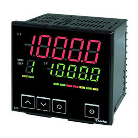
COMMUNICATION INSTRUCTION MANUAL No. BCx2CE5 2018.02 This manual contains instructions for communication functions of the BCD2, BCR2, BCS2. Serial communication and Console communication cannot be used together. When performing Serial communication, remove the tool cable (CMD-001) from the USB port of the PC and console connector of the BCD2, BCR2, BCS2.
Page 2
2. Wiring 2.1 When Using USB Communication Cable CMC-001-1 (sold separately) USB communication cable BCS2 BCR2, BCD2 CMC-001-1 (sold separately) YA(-) ⑯ YA(-) ⑩ YA(-) YB(+) ⑰ YB(+) ⑪ YB(+) ⑱ SG ⑫ SG Host computer USB port Shield wire ⑯...
Page 3
The terminator is mounted at the end of the wire when connecting multiple peripheral devices to a personal computer. The terminator prevents signal reflection and disturbance. Do not connect a terminator to the communication line because each BCD2, BCR2, BCS2 has built-in pull-up and pull-down resistors.
• Selects communication protocol. • Selection item: Shinko protocol Modbus ASCII Modbus RTU Shinko protocol (JC command allocated) Modbus ASCII (JC command allocated) Modbus RTU (JC command allocated) Instrument number • Sets the instrument number. The instrument numbers should be set one by one when multiple instruments are connected in Serial communication, otherwise communication is impossible.
Page 5
• Setting range: 0 to 1000 ms SVTC bias • By connecting to Shinko programmable controllers [PC-900 or PCD-33A with the SVTC (Set value digital transmission) option], digital SV via the SVTC command can be received from programmable controllers.
(Fig. 4-1) • Broadcast address (Modbus protocol) is set. • Communication error (framing error, parity error) • Checksum error (Shinko protocol), LRC discrepancy (Modbus ASCII mode), CRC-16 discrepancy (Modbus RTU mode) Communication timing of the RS-485 Master Side (Take note while programming)
Page 7
5. Shinko Protocol 5.1 Transmission Mode Shinko protocol is composed of ASCII. Hexadecimal (0 to 9, A to F), which is divided into high order (4-bit) and low order (4-bit) out of 8-bit binary data in command is transmitted as ASCII characters.
Page 8
(5) Negative acknowledgement Header Error Delimiter Address Checksum (15H) code (03H) Header: Control code to represent the beginning of the command or the response. ASCII is used. Write command, Read command: STX (02H) fixed Response with data, Acknowledgement: ACK (06H) fixed Negative acknowledgement: NAK (15H) fixed Instrument number (Address): Numbers by which the master discerns each slave.
Page 9
5.3 Checksum Calculation Checksum is used to detect receiving errors in the command or data. Set the program for the master side as well to calculate the checksum of the response data from the slaves so that communication errors can be checked. The ASCII code (hexadecimal) corresponding to the characters which range from the address to that before the checksum is converted to binary notation, and the total value is calculated.
Page 10
5.4 Command Example Numerals written below the command represent number of characters. (1) Read [Address 1, PV (0100H)] • Read command from the master Header Address Command Data item Checksum Delimiter address type [0100H] (02H) (21H) (20H) (20H) (30H 31H 30H 30H) (44H 45H) (03H) •...
Page 11
(4) Write (Address 1, Program pattern data) (Write multiple pieces of data) Example of program pattern setting Step SV ( ) Time 1:00 2:00 0:30 1:00 2:00 Wait value ( ) 1:00 2:00 0:30 1:00 2:00 Program control starts (Fig. 5.4-1) When writing the above program pattern, Command data in the message becomes as follows.
Page 12
• Response from the slave in normal status Header Address Checksum Delimiter (06H) (21H) (44H 46H) (03H) (5) Read (Address 1, Program pattern data) (Read multiple pieces of data) • Read command from the master [Amount of data: 15 (000FH), when reading the program pattern data on p.11] Header Address...
6. Modbus Protocol 6.1 Transmission Mode There are 2 transmission modes (ASCII and RTU) in Modbus protocol. 6.1.1 ASCII Mode Hexadecimal (0 to 9, A to F), which is divided into high order (4-bit) and low order (4-bit) out of 8-bit binary data in command is transmitted as ASCII characters. Data format Start bit: 1 bit Data bit: 7 bits (8 bits) (Selectable)
Page 14
2 (02H) Illegal data address (Non-existent data address) 3 (03H) Illegal data value (Value out of the setting range) Shinko protocol error code 4 17 (11H) (Status unable to be written. (e.g.) AT is performing.) 18 (12H) Shinko protocol error code 5...
Page 15
Add a value of 1 to X. This is assumed as X. Set X as an LRC to the end of the message. Convert the whole message to ASCII characters. RTU Mode After calculating CRC-16 (Cyclic Redundancy Check) from the slave address to the end of the data, the calculated 16-bit data is appended to the end of message in sequence from low order to high order.
Page 16
6.4 Message Example 6.4.1 ASCII Mode Numerals written below the command represent the number of characters. (1) Read [Slave address 1, PV (0100H)] • A request message from the master Header Slave Function Data item Amount of data Error check Delimiter address code...
Page 17
(4) Write (Slave address 1, Program pattern data) (Write Multiple pieces of data) Example of program pattern setting Step SV ( ) Time 1:00 2:00 0:30 1:00 2:00 Wait value ( ) 2:00 0:30 1:00 1:00 2:00 Program control starts (Fig.
Page 18
• A response message from the slave in normal status Header Slave Function Data item Data Error check Delimiter address code [1000H] [000FH] CR+LF (3AH) (30H 31H) (31H 30H) (31H 30H 30H 30H) (30H 30H 30H 46H) (44H 30H) (0DH 0AH) (5) Read (Slave address 1, Program pattern data) (Read multiple pieces of data) •...
Page 19
6.4.2 RTU Mode Numerals written below the command represent number of characters. (1) Read [Slave address 1, PV (0100H)] • A request message from the master Slave Function Data item Amount of data Error check 3.5 idle 3.5 idle address code CRC-16 characters...
Page 20
(4) Write (Slave address 1, Program pattern data) (Write multiple pieces of data) Program pattern setting example Step SV ( ) Time 1:00 2:00 0:30 1:00 2:00 Wait value ( ) 1:00 2:00 0:30 1:00 2:00 Program control starts (Fig. 6.4.2-1) When writing the above program pattern, Data in the message becomes as follows.
Page 21
• Response message from the slave in normal status Slave Function Data item Data Error check 3.5 idle 3.5 idle address code CRC-16 characters characters (01H) (10H) (1000H) (000FH) (84CDH) (5) Read (Slave address 1, Program pattern data) (Read multiple pieces of data) •...
Page 22
6.5 Diagnostics Function Modbus protocol has the following diagnostics functions. • Echoes back the request message. • Reads device identification information. 6.5.1 Message Configuration ASCII mode Slave Header Function Error check Delimiter Delimiter Data address code (CR) (LF) RTU mode Slave 3.5 idle 3.5 idle...
Page 23
01H/04H (Corresponds to Basic category) 00 Vendor name Object ID 1 Byte SHINKO TECHNOS CO., LTD. 01 Product code (model) (e.g.) BCS2R00-00 02 Version number (D, T, MP) (e.g.) Dxx-xxxx-xx, MPxxxx-xx Response message from the slave is composed of Sub-function code 14 (0EH) (for request), Read Device ID code and Object ID.
Page 24
3.5 idle 3.5 idle address code code CRC-16 characters characters (01H) (2BH) (0EH) (0400H) (7327H) • Response message from the slave in normal status (SHINKO TECHNOS CO., LTD.) Slave Function Sub-function 3.5 idle address code code characters (01H) (2BH) (0EH) Data...
Page 25
(3) Read Slave address 1, Device identification information (Product code) • A request message from the master Slave Function Sub-function Data Error check 3.5 idle 3.5 idle address code code CRC-16 characters characters (01H) (2BH) (0EH) (0401H) (B2E7H) • Response message from the slave in normal status (BCD2R00-01) Slave Function Sub-function...
Page 26
(Modbus RTU) is selected, communication commands (pp. 26 to 35) can be used. (Shinko protocol, JC command allocated), (Modbus ASCII, JC command allocated) or (Modbus RTU, JC command allocated) is selected, JC command (pp. 36 to 40) can be used.
Page 27
Shinko Modbus Command Function Data Item Data Type Code 0000H: No event 20/24/50/54H 03/06/10H 0006H Event output EV1 0001H: Alarm output, High limit alarm allocation (*1) 0002H: Alarm output, Low limit alarm 0003H: Alarm output, High/Low limits alarm 0004H: Alarm output, High/Low limits...
Page 28
Shinko Modbus Command Function Data Item Data Type Code 20/24/50/54H 03/06/10H 000BH Transmission output type 0000H: PV transmission 0001H: SV transmission 0002H: MV transmission 0003H: DV transmission 20/24/50/54H 03/06/10H 000CH Transmission output high limit Set value, Decimal point ignored 20/24/50/54H...
Page 29
Shinko Modbus Command Function Data Item Data Type Code 20/24/50/54H 03/06/10H 002CH Reserved (*2) 20/24/50/54H 03/06/10H 003BH Reserved (*2) 20/24/50/54H 03/06/10H 003CH OUT1 proportional band Set value, Decimal point ignored 20/24/50/54H 03/06/10H 003DH Integral time Set value 20/24/50/54H 03/06/10H 003EH Derivative time...
Page 30
Shinko Modbus Command Function Data Item Data Type Code 20/24/50/54H 03/06/10H 005EH Indication time Set value 20/24/50/54H 03/06/10H 005FH OUT1 MV preset value Set value, Decimal point ignored 20/24/50/54H 03/06/10H 0060H OUT2 MV preset value Set value, Decimal point ignored...
Page 31
7.1.2 A Single Piece of Data Read/Write Command Shinko Modbus Command Function Data Item Data Type Code 20H/50H 03H/06H 00E0H OUT/OFF key function 0000H: Control output OFF function 0001H: Auto/Manual control 0002H: Program control 20H/50H 03H/06H 00E1H Remote/Local 0000H: Local...
Page 32
7.1.4 Read Command Shinko Modbus Command Function Data Item Data Type Code 20H/24H 03H/04H 0100H Read value, Decimal point ignored 20H/24H 03H/04H 0101H OUT1 MV Read value, Decimal point ignored 20H/24H 03H/04H 0102H OUT2 MV Read value, Decimal point ignored...
Page 33
Shinko Modbus Command Function Data Item Data Type Code B0: Error 01 0: OFF 1: ON 20H/24H 03H/04H 010FH Error status B1: Error 02 0: OFF 1: ON flag 1 (*8) B2: Reserved B3: Reserved B4: Error 05 0: OFF...
Page 34
If a single/multiple piece(s) of data is/are written, data will be discarded, and acknowledgement will be returned. (*3) For ‘Not used’ items, if a single/multiple piece(s) of data Read/Write is/are executed, Error code 1 (31H, Shinko protocol) or Exception code 2 (02H, Modbus protocol) will be returned.
Page 35
(*7) If 00FFH (Key operation change flag clearing) is read, Error code 1 (31H, Shinko protocol) or Exception code 2 (02H, Modbus protocol) will be returned. If any value except 0001H (Clear key operation change flag) is written, Error code 3 (33H, Shinko protocol) or Exception code 3 (03H, Modbus protocol) will be returned.
Page 36
7.2 JC Command Table (Shinko protocol, JC command allocated), (Modbus ASCII, JC command allocated) or (Modbus RTU, JC command allocated) is selected in [Communication protocol], the following JC command can be used. 7.2.1 A Single Piece of Data Read/Write Command...
Page 37
Shinko Modbus Command Function Data Item Data Type Code 0023H Event output EV1 allocation 0000H: No event 20H/50H 03H/06H 0001H: Alarm output, High limit alarm (*2)(*7) 0002H: Alarm output, Low limit alarm 0003H: Alarm output, High/Low limits alarm 0004H: Alarm output, High/Low limit range...
Page 38
Shinko Modbus Command Function Data Item Data Type Code 003DH Not used 20H/50H 03H/06H (*1) 003EH Not used 20H/50H 03H/06H (*1) 003FH Not used 20H/50H 03H/06H (*1) EV1 alarm 0000H: Energized 20H/50H 03H/06H 0040H Energized/De-energized 0001H: De-energized EV2 alarm 0000H: Energized...
Page 39
Change in key operation 0: No 1: Yes (*1) For ‘Not used’ items, if a single piece of data Read/Write is executed, Error code 1 (31H, Shinko protocol) or Exception code 2 (02H, Modbus protocol) will be returned. (*2) The Read/Write range of setting values is different from that of keypad operation.
Page 40
(*9) For 0038H (Auto/Manual control), if Auto/Manual control is not selected in [OUT/OFF key function], Error code 1 (31H, Shinko protocol) or Exception code 2 (02H, Modbus protocol) will be returned. (*10) For 0039H (Manual control MV), if Write is executed during automatic control, Error code 1 (31H, Shinko protocol) or Exception code 2 (02H, Modbus protocol) will be returned.
Page 41
7.4 Negative Acknowledgement 7.4.1 Error code 1 (31H, Shinko protocol) or Exception code 2 (02H, Modbus protocol) The slave will return Error code 1 (31H, Shinko protocol) or Exception code 2 (02H, Modbus protocol) in the following case. • When non-existent data item is read or written.
Page 42
When acknowledgement is returned; Consider it as settings completed, and read all set values. When Error code 5 (35H, Shinko protocol) or Exception code 18 (12H, Modbus protocol) is returned as a negative acknowledgement; Consider it as still in setting mode, and read the requisite minimum pieces of data such as 0100H (PV)
Page 43
To communicate with a PLC, use a Shinko PLC Interface Unit SIF-600. No programming is needed for connection. Shinko protocol 24H (Multiple pieces of data read command) and 54H (Multiple pieces of data write command) are not available. PLCs corresponding to the SIF-600, its manufacturer and host link units:...
Page 44
7.7 Items to be Initialized by Changing Settings 7.7.1 Shinko protocol/Modbus ASCII/Modbus RTU If settings are changed, the following items will be initialized. : Initialized : Not initialized Setting item to be Event output Event output Transmission Input type Item...
Page 45
7.7.2 JC Command For the JC command, the following items will be initialized when settings are changed. : Initialized : Not initialized Setting item to be changed Event output Event output Input type Item EV1 allocation EV2 allocation (0044H) to be initialized (0023H) (0024H) SV1 (0001H)
Page 46
8. Set Value Digital Transmission By connecting to Shinko programmable controllers [PC-900 or PCD-33A with the SVTC (Set value digital transmission) option], digital SV via the SVTC command can be received from programmable controllers. 8.1 Wiring For the PC-900, connect YA (-) to YA (-), YB (+) to YB (+), COM (PC-900) to SG (BCx2) terminal respectively.
Max 31 units to 1 host computer Error correction Command request repeat system Error detection Parity, checksum (Shinko protocol), LRC (Modbus ASCII), CRC-16 (Modbus RTU) Digital external setting Receives digital SV via the SVTC command from Shinko programmable controllers (PC-900, PCD-33A with the SVTC option).
The BCx2 is in front keypad operation Return the controller to RUN mode. setting mode. For all other malfunctions, please contact our main office or dealers. SHINKO TECHNOS CO., LTD. OVERSEAS DIVISION Head Office 2-5-1, Senbahigashi, Minoo, Osaka, Japan http://www.shinko-technos.co.jp/e/...
Need help?
Do you have a question about the BCR2 and is the answer not in the manual?
Questions and answers