Advertisement
Available languages
Available languages
Quick Links
Cross Reference
Old Part #
Q345A1008
Q345A1016
Q345A1024
Q345A1065
Q345A1156
Q345A1305
Q345A1313
Q345A1321
Q345A1446
Q345A1701
Q345A1750
Q345A1818
Q345A2030
Q345A2055
Q345A2196
Q345A2360
Q345A2386
Q345A2402
Q345A2816
Q345A2824
Q345AFA
Q345AFB
Q345AFK
Q345AKB
Q345ALA
Q345ALB
Q345U1005
3
4
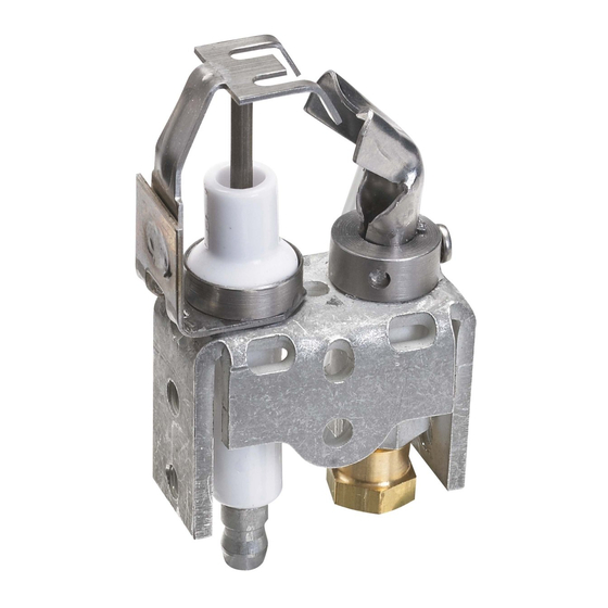
Mount Pilot Burner
Use the included screws to mount the Pilot Burner. Use the
See Cross Reference for orifice and sizes.
Auxiliary Mounting Bracket if needed.
Position the Pilot Burner so the pilot flame is aimed at the
main burner exactly the same way as the original pilot
burner flame.
Cut off the old compres-
sion fitting and replace
with the new compres-
sion fitting provided with
the new pilot burner.
TOO LOW
TOO HIGH
Never use the old com-
pression fitting because
it might not provide a
ORIGINAL
gas-tight seal.
LOCATION
MCR33962
WaRNING
FIRE OR EXPLOSION HaZaRD. CaN CaUSE
PROPERTY DaMaGE, SEVERE INJURY, OR DEaTH.
FIRE OR EXPLOSION HaZaRD. CaN CaUSE
PROPERTY DaMaGE, SEVERE INJURY, OR
Pilot burner flame alignment to the main burner is critical
DEaTH.
to safe appliance operation. Carefully read all installation
instructions. Replace only those pilots listed in the
Orifice must be the same size as the original orifice.
literature.
(Use only as a replacement for these Honeywell pilots)
Key
†
Compression
Set Hood
Use Orifice
Bracket
Fitting
L
Orange Bag
1/4 in.
No
Set Hood To
L = 20° Left
F = Front
L
Gray Bag
1/4 in.
No
R = 20° Right
F
Orange Bag
1/4 in.
No
Use Orifice
As Shipped = BCR-20 (0.020 in)
F
Orange Bag
1/4 in.
Yes
Natural gas
F
As Shipped
1/4 in.
No
Orange Bag = BCR-18 (0.018 in.)
F
Orange Bag
1/4 in.
*
Natural gas
L
Orange Bag
1/4 in.
*
Gray Bag = BBR-12 (0.012 in.) LP gas
Red Bag = BBR-11 (0.011 in.) LP gas
R
Orange Bag
1/4 in.
*
L
Red Bag
1/4 in.
Yes
†
Colors refer to the color of the label
F
Orange Bag
1/4 in.
No
on the bag.
F
Orange Bag
1/8 in.
No
*
Check Application
L
Orange Bag
1/8 in.
No
L
As Shipped
1/4 in.
No
F
As Shipped
1/4 in.
No
L
As Shipped
1/4 in.
Yes
L
Orange Bag
1/4 in.
No
L
Red Bag
1/4 in.
No
L
As Shipped
1/4 in.
No
L
Orange Bag
1/4 in.
No
L
Gray Bag
1/4 in.
No
F
*
*
Yes
F
*
*
No
F
*
*
No
R
*
*
No
L
*
*
Yes
L
*
*
No
*
*
*
*
5
Install the Correct Orifice
Connect the Ignition
and Compression Fitting
Cable and Ground Wire
Orifice
Compression fitting
(1/4 in. or 1/8 in.;
check application)
WaRNING
NOTE: Connect ground wire if present or applicable.
Note
FIRE OR EXPLOSION HaZaRD. CaN CaUSE
This pilot replaces only Honeywell standard single-rod,
PROPERTY DaMaGE, SEVERE INJURY, OR DEaTH.
hood-style intermittent pilot burners that do not have an
Follow these warnings exactly:
integral ignition and sensing wire.
1.
Disconnect power supply before wiring to prevent electrical
It will not replace batwing style pilot burners or pilot burn-
ers that have an integral ignition wire or standing pilot
shock or equipment damage.
burners.
2.
To avoid dangerous accumulation of fuel gas, turn off gas
supply at appliance service valve before starting installa-
•
For batwing-style intermittent pilot burners see the
tion and perform Gas Leak Test after completion of instal-
Q348U.
lation.
•
For hood-style intermittent pilot burners with an inte-
3.
Do not bend pilot tubing within 3 inches of the gas control
gral ignition wire see the Q3451U.
or pilot burner after compression nut has been tightened.
Gas leakage at the connection can result.
•
For standing pilot applications with standard hood-
Follow the appliance manufacturer instructions, if available;
style pilot burners see the Q314U.
otherwise, use the instructions provided.
1
The specifications given here do not include normal manu-
facturing tolerances. Therefore, this unit may not exactly
match the listed specifications.
This product is tested and calibrated under closely
controlled conditions, and some minor differences in
performance should be expected if those conditions are
A
Make sure gas is shut off.
changed.
WHEN INSTaLLING THIS PRODUCT...
B
Remove old Pilot Burner, including the old compres-
sion fitting.
1.
Read these instructions carefully. Failure to follow
instructions can damage equipment or cause a hazard-
C
Match the old model number to the Cross Reference.
ous condition.
D
Use the information in the Cross Reference to install
2.
Check cross reference in the installation guide or box to
the Pilot Burner.
verify the pilot is suitable for your application.
3.
Installer must be a trained, experienced service techni-
cian.
4.
After completing installation, use these instructions to
check out product operation.
6
7
Gas Leak Test and
Checkout
Gas Leak Test
The pilot flame should envelop 3/8 to 1/2 in. (10 to 13 mm) of
the igniter-sensor tip.
A
Make sure warning card has been removed from the pilot.
B
Turn on gas supply.
A
Turn off the system.
C
Use a gas sniffer* or paint the pipe connections upstream
B
Disconnect the lead to the MV terminal on the gas control.
of the pilot burner with a rich soap and water solution to
C
Light the pilot by setting the thermostat above room tem-
check for leaks. Bubbles indicate a gas leak.
perature to call for heat.
D
If a leak is detected, tighten the pipe connections.
D
Remove the pilot adjustment cover screw from the gas
E
Stand clear of the main burner while lighting to prevent
control.
injury from hidden leaks, which can cause flashback in the
E
Turn the inner pilot adjustment screw clockwise to
appliance vestibule.
decrease or counterclockwise to increase the pilot flame.
F
Set the thermostat to call for heat to light the main burner.
F
Replace the pilot adjustment cover screw and tighten firm-
G
With the main burner in operation, paint the pipe joints
ly after adjustment is complete to ensure proper operation.
(including the adapters) and gas control inlet and outlet
with rich soap and water solution or use a gas sniffer* to
NOTE: If Pilot flame is too small and cannot be adjusted to a
check for leaks.
larger size, a larger orifice may be needed. Check application
H
If another leak is detected, tighten the adapter screws,
requirements. If Pilot flame is too large and cannot be adjusted
joints, and pipe connections.
to a smaller size, a smaller orifice may be needed. Check appli-
I
Replace the part if the leak cannot be stopped.
cation requirements.
J
Do not proceed until all gas leaks are eliminated.
*
See AHRI video for proper use and considerations when
using an electronic gas sniffer
Checkout
Cycle the furnace through several cycles to ensure proper
smooth light off.
WaRNING
FIRE OR EXPLOSION HaZaRD. CaN CaUSE
PROPERTY DaMaGE, SEVERE INJURY, OR DEaTH.
FIRE OR EXPLOSION HaZaRD. CaN CaUSE
PROPERTY DaMaGE, SEVERE INJURY, OR DEaTH.
Using the incorrect orifice or pilot hood can cause an
unstable pilot, too large or too small of a pilot, pilot out-
Check for gas leaks any time work is done on a gas
age, reduced pilot life, improper lightoff, or gas buildup.
system.
2
Set the Hood
WaRNING
See Cross Reference for position.
a
B
Remove the Old Pilot
Burner
WaRNING
FIRE OR EXPLOSION HaZaRD. CaN CaUSE
PROPERTY DaMaGE, SEVERE INJURY, OR DEaTH.
Pilot flame must be positioned in the exact same posi-
tion with respect to the main burner. The screw must be
installed through the pilot hood and into the spud, so
the head of the screw is flush with the adapter. Failure
to properly orient the pilot flame and/or secure the pilot
hood may create an explosion hazard.
adjust Pilot Flame
For additional information and a full-length product data
document, scan this QR code or to go
www.customer.honeywell.com/universalpilot1.
automation and Control Solutions
Honeywell International Inc.
1985 Douglas Drive North
Golden Valley, MN 55422
Honeywell Ltd
705 Montrichard Avenue
Saint-Jean-sur-Richelieu, Québec
J2X 5K8
WaRNING
http://customer.honeywell.com
® U.S. Registered Trademark.
© 2013 Honeywell International Inc.
69-2755EF—03 M.S. Rev. 06-13
Printed in U.S.A.
SET HOOD
SET HOOD
RIGHT
LEFT
C
SET HOOD
FRONT
MCR34028
Advertisement

Related Manuals for Honeywell Q345U


Summary of Contents for Honeywell Q345U
- Page 1 Set the Hood Note Cross Reference WaRNING (Use only as a replacement for these Honeywell pilots) FIRE OR EXPLOSION HaZaRD. CaN CaUSE This pilot replaces only Honeywell standard single-rod, PROPERTY DaMaGE, SEVERE INJURY, OR DEaTH. hood-style intermittent pilot burners that do not have an †...
- Page 2 Réglage de la coiffe Remarque Correspondances aVERTISSEMENT (utiliser uniquement pour remplacer ces veilleuses Honeywell) Cette veilleuse remplace uniquement les veilleuses RISQUE D’INCENDIE OU D’EXPLOSION. PEUT CaUSER DES DÉGÂTS ET DES BLESSURES GRaVES, intermittentes à coiffe et à tige unique sans allumage Légende...
Need help?
Do you have a question about the Q345U and is the answer not in the manual?
Questions and answers