Table of Contents
Advertisement
Quick Links
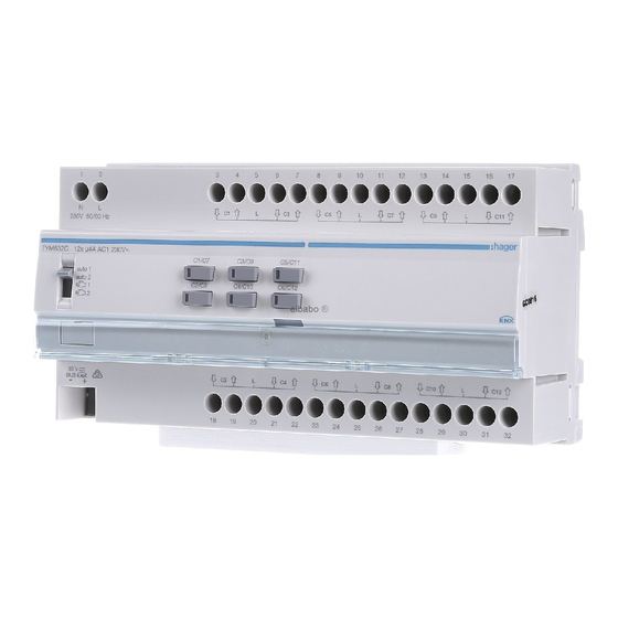
Design and layout of the device
(7)
z
1
2
N
L
230V 50/60 Hz
auto 1
auto 2
(1)
(2)
Bn?.:
M `
Figure 1: Device overview
(1) Slide switch auto1/auto2/
TYM632C
(2) KNX bus connection terminal
Output 12gang shutter/blind
(3) Connections of loads
230 V AC
(4) Labelling fi eld with cover
(5) Illuminated programming button
TXM632C
(6) Operation button for manual operation per
Output 12gang shutter/blind
output with status LED
230 V AC
(7) Mains power supply connection
Function
System information
This device is a product of the KNX system and
corresponds to the KNX guidelines. Detailed
specialised knowledge obtained from KNX training
courses
is required for understanding. The planning, instal-
lation and commissioning of the device is carried
out with the help of KNX-certifi ed software.
Systemlink commissioning:
Safety instructions
z
The function of the device is software-depend-
Electrical equipment may only be installed and
ent. The software is to be taken from the product
assembled by a qualifi ed electrician in accord-
database. You can fi nd the latest version of the
ance with the relevant installation standards,
product database, technical descriptions as well as
guidelines, regulations, directives, safety and
conversion and additional support programmes on
accident prevention regulations of the country.
our website.
Failure to comply with these installation in-
Easylink commissioning:
structions may result in damage to the device,
The function of the device is confi guration-de-
fi re or other hazards.
pendent. The confi guration can also be done using
Hazard due to electric shock. Disconnect be-
devices developed specially for simple setting and
fore working on the device or load. Take into
start-up.
account all circuit breakers that supply danger-
This type of confi guration is only possible with
ous voltages to the device or load.
devices of the easylink system. Easylink stands for
Connect one motor per output only. If several
easy, visually supported start-up. Preconfi gured
motors are connected, motors or device might
standard functions are assigned to the in/outputs
be destroyed.
by means of a service module.
Use drives with mechanical or electrical fi nal
Functional description
position switches only. Check fi nal position
switches for correct adjustment. Observe mo-
The device is used to control motor-operated build-
tor manufacturer's data. The device can be
ing fi ttings such as shutters and blinds via the KNX
damaged.
bus. The device has 12 outputs from which each
output can be activated independently.
Do not connect any three-phase motors. The
device can be damaged.
Correct use
Risk of injury. Use the device to control blind
- Switching electrically operated motors of 230 V
and shutter drives or awnings only. Do not
AC for blinds, shutters, awnings and similar
switch any other loads.
hangings
- Mounting on DIN rail according to DIN EN
Observe the motor manufacturer's data regard-
60715 in the distribution box
ing change-over time and max. switch-on time
(ED).
Product characteristics
These instructions are an integral component
- independent outputs, activation via KNX bus
of the product and must be retained by the end
- Status display of the outputs on the device
user.
- manual activation of the outputs on the device
possible, building site operation
- Position can be started directly
- 3 Alarms
- Scene function
1
- Forced position by higher-level controller
- Connection of various external conductors
(3)
possible
- Slat position directly controllable
3
4
5
6
7
8
9
10
11
12
13
14
15
16
17
Operation
L
L
C9
L
C11
Manual operation switch on/off
C1/C7
C3/C9
C5/C11
Bus and mains power supply are present.
C2/C8
C4/C10
C6/C12
(6)
Push switch (1) to position
1/
Manual operation is switched on, the outputs
(4)
(5)
can be controlled using the operation buttons
(6) independently of each other.
C2
L
C4
C6
L
C8
C10
L
C12
1 switches on the control of the outputs
C1 .. C6.
18
19
20
21
22
23
24
25
26
27
28
29
30
31
32
2 switches on the control of the outputs
(3)
C7 .. C12.
During manual operation, the controller is deac-
P
tivated via the KNX bus.
1/
2
Systemlink commissioning:
P
Depending on the programming, the manual
operation is activated permanently or for a time
period confi gured via the application software.
If the manual operation is blocked via the appli-
cation software, no activation takes place.
Or:
Move switch (1) to position auto1/auto2.
The manual operation is switched off. Operation
takes place solely via the KNX bus. The output
adopts the position predefi ned by the bus con-
troller. The switching status is displayed via the
status LED of the operation button (6).
auto 1 displays the status of the outputs C1 ..
C6.
auto 2 displays the status of the outputs C7 ..
C12.
Operating outputs in manual operation
Operation takes place per output by briefl y pressing
the operation button repeatedly (table1).
Status
Behaviour when
button pressed briefl y
Output is in idle
Movement operation starts.
state,
Status LED of button (6)
status LED of the
lights up.
1)
button (6) is off.
Output active,
Movement operation stops,
status LED of the
LED goes out.
button (6) lights
up.
1)
1)
The LED lights up red during upward travel and green
during downward travel.
Table 1: Manual operation
Information for electricians
Installation and electrical connection
DANGER!
ç
Touching live parts can result in an
electric shock!
An electric shock can be lethal!
Disconnect the connecting cables
2.
before working on the device and
cover all live parts in the area!
CAUTION!
ç
Risk of destruction if parallel connec-
tion of several motors on one output!
Final position switches could fuse
together. Motors, hangings and the
device may be destroyed!
Only connect one motor per
output!
Installing the appliance
Observe temperature range. Provide suffi cient
P
cooling.
Mount device onto DIN rail in accordance with
DIN EN 60715.
Connecting the device (Figure 2)
The installation circuit must be protected via circuit
breaker 10 A.
Connect bus cable via connecting terminal (2).
Connect mains voltage (7).
Connect motors.
Start-up
Systemlink: Loading physical address and
application software
The switch (1) is in auto1/auto2.
L3
L2
L1
N
1
2
3
N
L
230V 50/60 Hz
C1/C7
auto 1
auto 2
C2/C8
18
N
L1
L2
L3
Fig 2: Device connection
Hager Controls S.A.S., 33 rue Saint-Nicolas, B.P. 10140, 67703 SAVERNE CEDEX, France - www.hager.com
Switch on bus voltage.
Functional test
Press programming button (5).
The functionality of the outputs is displayed via the
status LED of the operation button (6).
The button lights up.
If the button does not light up, no bus voltage is
P
Appendix
present.
Technical data
Load the physical address into the device.
Status LED of the button goes out.
KNX medium
Load application software.
Confi guration mode
Note down the physical address on the labelling
Rated voltage KNX
fi eld (4).
Own consumption on the KNX bus:
- typical
Easylink:
- in standby
Information on the system confi guration can be
Auxiliary voltage
taken from the extensive description of the service
module easylink.
Mains frequency
Power dissipation maximum
Starting up the device
Own consumption on mains:
Switch on mains voltage on the outputs.
- maximum
Switch on mains supply.
- in standby
Determine operation time and slat adjusting
Breaking capacity
time
Switching current at cos Φ = 0.6
In blind/roller shutter operation, the operation time
Operating altitude
for positioning the sunshade is important. The posi-
Degree of contamination
tion is calculated based on the operation time. The
Surge voltage
slat adjusting time for slat blinds, determined by
the design, is part of the total operation time. The
Degree of protection of housing
opening angle of the slats is therefore set as oper-
Degree of protection of housing
ation time between opened and closed position.
under front panel
The operation time for UP is normally longer
P
Impact protection
than the operation time for DOWN and must be
Overvoltage class
measured separately if necessary.
Operating temperature
Measure UP and DOWN operation time of the
hanging.
Storage/transport temperature
Measure slat adjusting time between OPEN
Maximum switching cycle
and CLOSED.
rate at full load
Enter measured values into the parameter set-
Connection capacity
ting – running time... or slat step time.
Standards
Dimension
Troubleshooting
Manual operation not possible
Cause 1: Switch (1) not moved to
Move switch to
Cause 2: Manual operation has not been enabled
(Systemlink).
Enable manual operation via application soft-
ware.
Bus operation is not possible
4
5
6
7
8
9
10
11
12
13
14
15
16
17
Cause: Bus voltage is not present.
L
L
C9
L
C11
Check bus connection terminal for correct
polarity.
C3/C9
C5/C11
Check bus voltage by briefl y pressing the pro-
gramming button (5), red LED lights up if bus
C4/C10
C6/C12
voltage is present.
If mains voltage is available without bus voltage
- red LED of the programming button (5) blinks.
Cause 2 : Manual operation is active. Switch (1) is
in position
C2
L
C4
C6
L
C8
C10
L
C12
Move switch (1) to position auto1/auto1.
19
20
21
22
23
24
25
26
27
28
29
30
31
32
Shutters/blinds do not move to the fi nal
position
Cause: Operation time for the shutters/blinds set
incorrectly.
Check operation times. Measure again and
reprogram if necessary.
TP 1
S-Mode, E-Controller
s 30 V SELV
7 mA
5 mA
230 V AC, + 10 % .. - 15 %
240 V, + 6 % .. - 6%
50/60 Hz
3 W
5 W
0.2 W
µ230 V , 4 A AC1
max. 4 A
max. 2000 m
2
4 kV
IP 20
IP30
IK 04
III
-5 ...+ +45°C
-20°C ... +70°C
6 switching cycle/minute
0.5 mm² ... 6 mm²
EN50491-3 ; EN60669-2-1
10 TE, 10 x 17.5 mm
1/
2.
1/
2.
1/
2.
04/2015 - 6LE000349A
Advertisement
Table of Contents

Related Manuals for hager TYM632C


Summary of Contents for hager TYM632C
- Page 1 (1) Slide switch auto1/auto2/ Only connect one motor per - maximum Systemlink commissioning: Switch on mains supply. output! TYM632C (2) KNX bus connection terminal - in standby 0.2 W Depending on the programming, the manual Output 12gang shutter/blind (3) Connections of loads...
- Page 2 Hager Controls S.A.S., 33 rue Saint-Nicolas, B.P. 10140, 67703 SAVERNE CEDEX, France - www.hager.com 04/2015 - 6LE000349A...
Need help?
Do you have a question about the TYM632C and is the answer not in the manual?
Questions and answers