
Related Manuals for Velleman K2636


Summary of Contents for Velleman K2636
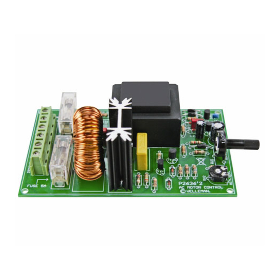
- Page 1 Total solder points: 95 Difficulty level: beginner 1 advanced UNIVERSAL AC MOTOR CONTROL K2636 ILLUSTRATED ASSEMBLY MANUAL H2636IP-1...
-
Page 2: Specifications
Features & Specifications This kit is especially designed to control the speed of drills or any other AC-motors with carbon brushes. Contrary to the usual dimmers, there isn't a phase cut every 1/2 period but only once per period. The moment of cutting determines the speed which can be adjusted from 5 to about 95 %. - Page 3 Assembly hints 1. Assembly (Skipping this can lead to troubles ! ) Ok, so we have your attention. These hints will help you to make this project successful. Read them carefully. 1.1 Make sure you have the right tools: • A good quality soldering iron (25-40W) with a small tip.
- Page 4 3- Trim excess leads as close as possible to the solder joint REMOVE THEM FROM THE TAPE ONE AT A TIME ! AXIAL COMPONENTS ARE TAPED IN THE CORRECT MOUNTING SEQUENCE ! You will find the colour code for the resistances and the LEDs on our website: http://www.velleman.be/common/service.aspx...
- Page 5 Construction 1. Jumper SK4 3. Resistors 4. Metal film resistors Mount jumper according to the main voltage : R... R... R9 : 100 (1 - 0 - 1 - B - 9) R10 : 120 (1 - 2 - 1 - B - 9) R1 : 4K7 (4 - 7 - 2 - B) R11 : 68...
- Page 6 Construction 7. Transistors. 10. Terminal blocks. 13. LED T1 : BC547B : 2p LD1 : 3mm RED T2 : BC547B LOAD : 2p T3 : BC547B MAINS : 2p LD... T4 : BC517 CATHODE 8. Capacitors 14. Coil. 11. Fuse holders + fuses L1 : 1mH/5A/1Khz.
- Page 7 Construction 16. Triac. TR1 : BT137F-600 10mm M3 BOLT 3 BOLT LOCK WASHER Place the heatsink and the triac on the PCB. Fix the two components with a M3 bolt and nut. Now, the triac may be soldered.
-
Page 8: Test & Connection
Test & connection 17. Test & connection ATTENTION: A PART OF THE CIRCUIT IS ALWAYS UNDER MAIN VOLTAGE. TAKE ALL POSSIBLE PRECAUTIONS, SO 110 - 240VAC THAT NO-ONE CAN TOUCH ANY PART. FOR YOUR OWN SECURITY AS FOR THE USERS' SECURITY. MOUNT THIS KIT PREFERABLY IN AN ISOLATING HOUSING. - Page 9 Test & connection Turn RV1 completely to the left (minimal position) and RV2 completely to the right. Switch the power on. BE CAREFUL: a large part of the circuit is under mains power, do not touch it! Adjust RV2 so that the motor will have the lowest speed. It is important for the motor to start at any time, even where RV1 is put in its minimal position, otherwise there might be large currents causing sparks that burn the carbon brushes.
-
Page 11: Schematic Diagram
Diagram Schematic diagram 470µF 1µF... - Page 12 VELLEMAN Components NV Legen Heirweg 33 9890 Gavere Belgium Europe www.velleman.be www.velleman-kit.com Modifications and typographical errors reserved © Velleman Components nv. H2636IP - 2004 - ED1 (rev.2) 5 4 1 0 3 2 9 3 1 1 4 1 4...
Need help?
Do you have a question about the K2636 and is the answer not in the manual?
Questions and answers