Advertisement
Quick Links
Total solder points: 115
Difficulty level:
beginner 1o 2o 3þ 4o 5oadvanced
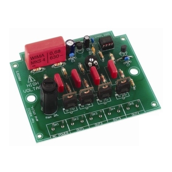
4 channel running light
Features:
þ Adjustable speed.
þ Suited for inductive loads.
þ 4 channels with LED indicator.
þ Ideal for disco effects.
þ Noise suppressed according to EN55015.
Specifications :
•
AC Power : 110 to 240 VAC.
•
t
Au
o frequency detection : 50/60Hz
•
Max load per channel 2A : 200W (110 - 125VAC)
•
Adjustable speed : 0,2 to 3Hz.
•
Dimensions : 100 x 82 x 35mm / 4 x 3,3 x 1,4"
Modifications reserved.
ILLUSTRATED ASSEMBLY MANUAL
.
400W (220 - 240VAC)
K8032
H8032IP-1
Advertisement

Related Manuals for Velleman K8032


Summary of Contents for Velleman K8032
-
Page 1: Specifications
Total solder points: 115 Difficulty level: beginner 1o 2o 3þ 4o 5oadvanced 4 channel running light K8032 Features: þ Adjustable speed. þ Suited for inductive loads. þ 4 channels with LED indicator. þ Ideal for disco effects. þ Noise suppressed according to EN55015. - Page 2 VELLEMAN Components NV Legen Heirweg 33 9890 Gavere Belgium Europe www.velleman.be www.velleman-kit.com...
- Page 3 Assembly hints 1. Assembly (Skipping this can lead to troubles ! ) Ok, so we have your attention. These hints will help you to make this project success- ful. Read them carefully. 1.1 Make sure you have the right tools: •...
- Page 4 Assembly hints 1.3 Soldering Hints : Mount the component against the PCB surface and carefully solder the leads Make sure the solder joints are cone-shaped and shiny Trim excess leads as close as possible to the solder joint AXIAL COMPONENTS ARE TAPED IN THE CORRECT MOUNTING SEQUENCE ! REMOVE THEM FROM THE TAPE ONE AT A TIME !
- Page 6 Construction 1. 1/4W Resistors 3. Diodes Watch the polarity ! R... D... CATHODE q D1 : 1N4007 q R4: 3K3 (3-3-2-B) q D2 : 1N4007 q R6: 270 (2-7-1-B) q R7: 270 (2-7-1-B) q R8: 270 4. Zenerdiode (2-7-1-B) q R9: 270 (2-7-1-B) Watch the polarity ! 2.
- Page 7 6. 1W Resistor 8. PCB tabs Construction R... q SK1 : Power (2X) q R1: 220 (2-2-1-B) q SK2 : Out1 (2X) q SK3 : Out2 (2X) 7. Capacitors q SK4 : Out3 (2X) q SK5 : Out4 (2X) 9. Trim potentiometer q C3 : 100n (104) q C4 : 100n (104) q C6 : 100p (101)
- Page 8 Construction 12. Electrolytic 15. Capacitors Capacitors. Watch the polarity ! C... q C1 : 680n / 600V q C2 : 220µF / 25V q C5 : 10µF / 35V 16. LED’s. Watch the polarity ! 13. Fuseholder + Fuse CATHODE q LD1: 3mm Red q F1 : 2A (slow) q LD2: 3mm Red...
- Page 9 Hook-up and use 18. Hook– up and use 200W at 110-125VAC 400W at 220-240VAC MAX ! For each channel. AC PLUG q Solder an AC cable to the SK1 pins (AC Power). q Solder the cables of each lampholder to the appropriate pins.
- Page 10 19. PCB layout.
- Page 11 Schematic diagram 20. Schematic diagram.
- Page 12 VELLEMAN Components NV Legen Heirweg 33 9890 Gavere Belgium Europe www.velleman.be www.velleman-kit.com Modifications and typographical errors reserved © Velleman Components nv. H8032IP - 2002 - ED1...
Need help?
Do you have a question about the K8032 and is the answer not in the manual?
Questions and answers