
Related Manuals for Velleman K8006


Summary of Contents for Velleman K8006
- Page 1 BASE UNIT for HOME MODULAR LIGHT SYSTEM Total solder points: 234 Difficulty level: beginner 1 5 ⌧ advanced K8006 K8006 ILLUSTRATED ASSEMBLY MANUAL H8006IP-2...
- Page 2 VELLEMAN NV Legen Heirweg 33 9890 Gavere Belgium Europe www.velleman.be www.velleman-kit.com...
-
Page 3: Specifications
Features & specifications Features : Create your own domestic modular light control system. For use with optional dimmer module (K8007), timer module (K8008), relay output module (K8027) and slow on-off dimmer (K8029). Bus system holds up to five plug-in units. Optically insulated push button inputs. - Page 4 Assembly hints 1. Assembly (Skipping this can lead to troubles ! ) Ok, so we have your attention. These hints will help you to make this project successful. Read them carefully. 1.1 Make sure you have the right tools: • A good quality soldering iron (25-40W) with a small tip.
- Page 5 Assembly hints ⇒ Use the check-boxes to mark your progress. ⇒ Please read the included information on safety and customer service * Typographical inaccuracies excluded. Always look for possible last minute manual updates, indicated as ‘NOTE’ on a separate leaflet. 1.3 Soldering Hints : 1- Mount the component against the PCB surface and carefully solder the leads...
- Page 6 Construction 1. Diodes (check the polarity) Resistors. 1/2W D... R... CATHODE R2 : 180 (1 - 8 - 1 - B - 9) D1 : 1N4148 R3 : 180 (1 - 8 - 1 - B - 9) D2 : 1N4148 R4 : 2K2 (2 - 2 - 2 - B - 9) D3 : 1N4148...
- Page 7 Construction 7. LEDs. Watch the polarity! 9. PC Terminal blocks (Slide the terminal blocks, one into each other) CATHODE 3mm RED SK6 to SK10 : 2P+2P+2P+2P+2P 8. PCB Edge Connectors (Watch the orientation!) SK... SK11 to SK13 : 2P+2P+2P HOT GLUE GUN LIJMPISTOOL PISTOLET A COLLE HEISKLEBEPISTOLE...
- Page 8 Construction 10. Fuse Holder + Fuse 13. Insert the OPTO Coupler into the socket (Watch the position of the notch!) F... IC... PIN 1 F1 : 2,5A SLOW F2 : 2,5A SLOW F3 : 2,5A SLOW F4 : 2,5A SLOW F5 : 2,5A SLOW 11.
-
Page 9: Testing The Unit
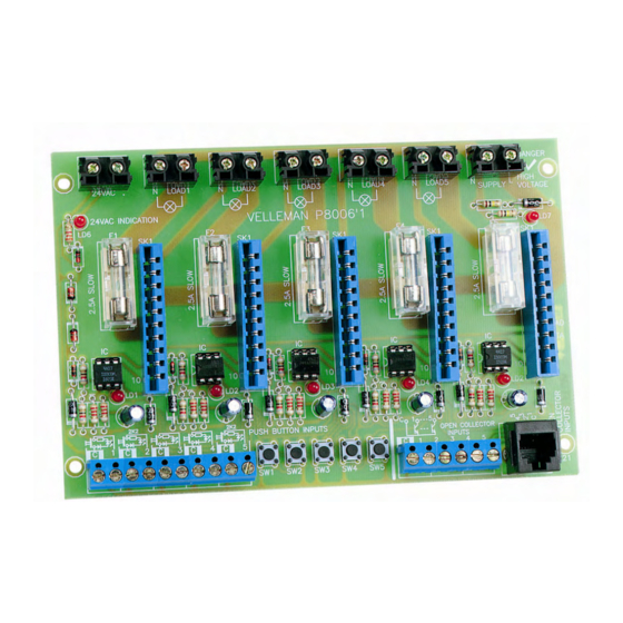
LOAD1 LOAD2 LOAD3 LOAD4 LOAD5 24VAC INDICATION VELLEMAN P8006'1 PUSH BUTTON INPUTS 1 C 2 C 3 C 4 C 5 1 2 3 4 5 SW 1 SW 2 SW3 SW4 SW5 Push button SW1. The module will be activated, and the light bulb will light. For dimmer/timer module operation details, please check their manuals. -
Page 10: Final Connection
24VAC VOLTAGE 24VAC LOAD1 LOAD2 LOAD3 LOAD4 LOAD5 SUPPLY VELLEMAN K8006 PRIM 4 C 5 1 C 2 C 3 C 1 2 3 4 5 SW1 SW2 SW3 SW4 SW5 AC POWER PUSH BUTTONS REMARK: 10 LEDs are provided,... - Page 11 HIGH 24VAC VOLTA GE 24VAC LOAD1 LOAD2 LOAD3 LOAD4 LOAD5 SUPPLY VELLEMAN K8006 PRIM 1 C 2 C 3 C 4 C 5 1 2 3 4 5 SW1 SW2 SW3 SW4 SW5 AC POW ER OPEN COLLECTOR OUTPUTS PUSH BUTTONS...
- Page 12 17. Home modular light system controlled by touchscreen (K8046) AC POWER DANGER HIGH 24VAC VOLTAGE 24VAC LOAD1 LOAD2 LOAD3 LOAD4 LOAD5 SUPPLY VELLEMAN K8006 PUSH BUTTON INPUTS SW1 SW2 SW3 SW4 SW5 PRIM AC POWER 2 x 9VAC GND VA VB + GND VELLEMAN K8046 PRIM AC POWER...
- Page 13 PCB Layout 18. PCB Layout...
- Page 14 Diagram 19. Diagram...
- Page 16 VELLEMAN KIT NV Legen Heirweg 33 9890 Gavere Belgium Europe Info ?: http://www.velleman.be Modifications and typographical errors reserved - © Velleman nv. H8006IP'2 - 2004 - rev.1 5 4 1 0 3 2 9 2 9 1 1 6 7...
Need help?
Do you have a question about the K8006 and is the answer not in the manual?
Questions and answers