Table of Contents
Advertisement
Quick Links
Advertisement
Table of Contents

Related Manuals for Amprobe CT-326-C


Summary of Contents for Amprobe CT-326-C
- Page 1 CT-326-C Current Tracer Users Manual 1.800.561.8187 information@itm.com www. .com...
- Page 2 1.800.561.8187 information@itm.com www. .com...
- Page 3 CT-326-C Current Tracer Users Manual P/N 2757388 Rev 002 11/2013, 6001572 A © 2013 Amprobe Test Tools. All rights reserved. 1.800.561.8187 information@itm.com www. .com...
- Page 4 Limited Warranty and Limitation of Liability Your Amprobe product will be free from defects in material and workmanship for one year from the date of purchase unless local laws require otherwise. This warranty does not cover fuses, disposable batteries or damage from accident, neglect, misuse, alteration, contamination, or abnormal conditions of operation or handling.
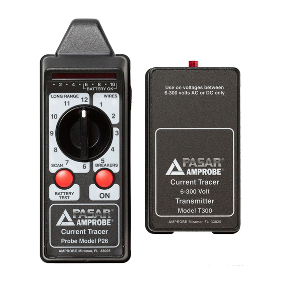
- Page 5 P26 Receiver 1) Probe tip 2) LED bar-graph indicator 3) Battery status check 4) Range switch 5) ON test mode: Push and hold to test 6) Battery test: Push and hold to check battery status 7) Earphone jack 8) Battery compartment T300 Transmitter 1) LED indicator 2) Fuse compartment...
-
Page 6: Table Of Contents
CT-326-C Current Tracer CoNTENTS SYMBOLS ........................5 INTRODUCTION ......................5 SYMBOLS AND WARNINGS ..................5 UNPACKING AND INSPECTION ................... 6 COMPONENTS DESCRIPTION ..................6 T300 (6-300 V) Transmitter ..................6 P26 Receiver ......................6 OPERATION ........................7 Transmitter Test Position ..................7 Receiver Sensitivity .................... -
Page 7: Symbols
Application around and removal from hazardous live conductors is permitted INTRodUCTIoN The Amprobe PASAR Current Tracer is a hand-held circuit tracing device for locating and tracing circuit breakers and “hot” and neutral conductors without turning off power or interrupting sensitive electronic equipment. -
Page 8: Unpacking And Inspection
8. When not in use, keep the instruments in their carrying case. 9. If the CT-326-C will not be used for a period of time, remove the battery to prevent leakage in the instrument. UNPACkING ANd INSPECTIoN... -
Page 9: Operation
oPERATIoN Transmitter Test Position IMPoRTANT: For locating and tracing applications, always use a voltmeter to determine the line voltage before connecting the transmitter. 1. Plug the transmitter into any standard electrical outlet (see Fig.1). If there is no outlet available, use the pigtail connector provided. -
Page 10: Distance From Wire For Half Scale Reading Approximate
RANGE SWITCH APPLICATIoNS WIRES (most selective) Locate conductor in bundles and conductors entering a breaker switch BREAKERS Locate individual circuit breaker switches and test position SCAN Locate conductors in floors, walls, ceilings, and conduit and correct breaker panels LONG RANGE Locate underground cables and wire to wire shorts (most sensitive) Receiver Range and Applications... -
Page 11: Circuit Breakers, Fuses
Receiver Test Position 1. To test the receiver’s battery, push the “Battery Test” button. If the LED display does not light up within the “Battery OK” area, replace the battery and repeat. 2. Turn the receiver’s range switch to “Breakers-5.” 3. -
Page 12: Neutral Lines Within A Breaker Panel
Fig.3 Correct the angle of the probe for accurate readings Neutral Lines within a breaker Panel Neutral lines may also be traced since the magnetic signal produced by the transmitter returns on the circuit’s neutral line. Follow steps 1-15 16. With the panel trim removed and the receiver’s range switch set on “Wires-1,” touch the receiver’s tip to the neutral wires in the breaker panel. -
Page 13: Wires In Floors, Walls, Ceilings
Wires in Floors, Walls, Ceilings IMPORTANT: Since the load current on the conductors supplying power to the transmitter flows in opposite directions on the “hot” and neutral wires, the magnetic field surrounding these conductors radiates in the opposite direction. (See Fig. 6). Therefore, when the “hot” and neutral wires are within close proximity, they tend to cancel the force of each other’s magnetic field. -
Page 14: Conduit
Individual Wires within bundles When tracing wires bundled together, it may be necessary to separate them to reduce magnetic coupling to nearby wires (see p.12). Conduit 1. Plug the pigtail connector into the transmitter. 2. Attach one of the pigtail connector’s insulated clip leads to a separate ground such as a water pipe. -
Page 15: Underground Wires And Buried Cables
Underground Wires and buried Cables 1. Plug the pigtail connector into the transmitter. 2. Attach one of the pigtail connector’s insulated clip leads to a separate ground such as a metal rod planted in the earth. 3. Attach the other lead to the “hot” conductor of the circuit you wish to trace. The transmitter’s LED will blink to indicate it is operating and that the circuit is complete. -
Page 16: Neutral Wires And Ground Wires
Typically, more voltage will be needed for dry soil and/or longer conductor lengths. Refer to the application notes of the CT-326-C to find the voltage that must be applied to the transmitter to overcome the effects of resistance and Inductance of the circuit to develop acceptable signal strength. -
Page 17: Wire To Wire Shorts
Wire to Wire Shorts 1. Use an ohmmeter to locate the shorted pair of conductors. 2. Disconnect the conductors from power. 3. Plug the pigtail connector into the transmitter. 4. Attach one of the pigtail connector’s insulated clip leads to either of the shorted conductors. 5. -
Page 18: Transmitter Fuse Replacement
4. The transmitter’s LED will blink to indicate that it is operating and that the circuit is complete (see Fig. 10). It is not necessary to disconnect the coax cable for this application. If the coax is connected, signal will travel toward ground in both directions and the strength will be reduced by one half. -
Page 19: Troubleshooting The Current Tracer
Troubleshooting the Current Tracer To test the operation of the transmitter, connect it to a known power source from 6 to 300 V ac/ dc. The LED should begin to blink at a steady rate of approximately 71 times per minute. If it does not blink, checks to ensure that there is proper voltage on the line and replace the fuse, if necessary. - Page 20 Visit www.Amprobe.com for • Catalog • Application notes • Product specifications • User manuals Amprobe ® www.Amprobe.com info@amprobe.com Everett, WA 98203 Tel: 877-AMPROBE (267-7623) Amprobe Europe ® Beha-Amprobe In den Engematten 14 79286 Glottertal, Germany Please Tel.: +49 (0) 7684 8009 - 0 Recycle 1.800.561.8187...
Need help?
Do you have a question about the CT-326-C and is the answer not in the manual?
Questions and answers