
Subscribe to Our Youtube Channel
Summary of Contents for GE Grid Solutions Multilin 9450
- Page 1 Grid Solutions Multilin™ 9450/9650 Advanced Power Quality Metering System Instruction Manual Software Revision: 1.32 Manual P/N: 1601-0159-A7 Manual Order Code: GEK-113281F *1601-0159-A7*...
- Page 2 Copyright © 2017 GE Multilin Inc. All rights reserved. EPM 9450/9650 Instruction Manual for product revision 1.32. The contents of this manual are the property of GE Multilin Inc. This documentation is furnished on license and may not be reproduced in whole or in part without the permission of GE Multilin.
-
Page 3: General Safety Precautions
GENERAL SAFETY PRECAUTIONS • Failure to observe and follow the instructions provided in the equipment manual(s) Note could cause irreversible damage to the equipment and could lead to property damage, personal injury and/or death. • Before attempting to use the equipment, it is important that all danger and caution indicators are reviewed. - Page 4 Indicates general information and practices, including operational information and practices, that are not related to personal injury. For further assistance For product support, contact the information and call center as follows: GE Grid Solutions 650 Markland Street Markham, Ontario Canada L6C 0M1...
-
Page 5: Table Of Contents
Table of Contents 1: THREE-PHASE POWER THREE PHASE SYSTEM CONFIGURATIONS ................1-1 MEASUREMENT WYE CONNECTION .......................... 1-1 DELTA CONNECTION ........................1-3 BLONDEL’S THEOREM AND THREE PHASE MEASUREMENT ......... 1-5 POWER, ENERGY AND DEMAND ....................1-6 REACTIVE ENERGY AND POWER FACTOR ................1-9 HARMONIC DISTORTION ...................... - Page 6 - VA ..............4-3 IRING THE ONITORED NPUTS .............. 4-3 IRING THE ONITORED NPUTS URRENTS ISOLATING A CT CONNECTION REVERSAL ................4-4 INSTRUMENT POWER CONNECTIONS ..................4-5 WIRING DIAGRAMS ......................... 4-6 5: COMMUNICATION COMMUNICATION OVERVIEW ....................5-1 WIRING RS232 CONNECTION (PORT 1) ....................5-5 RS485 COMMUNICATION ......................
- Page 7 9: EXTERNAL I/O HARDWARE OVERVIEW ......................... 9-1 MODULES ........................9-2 VERVIEW I/O MODULE INSTALLATION ......................9-4 I/O M ................9-4 OWER OURCE FOR ODULES USING THE PSIO WITH MULTIPLE I/O MODULES ............... 9-6 I/O M ............9-6 TEPS FOR TTACHING ULTIPLE ODULES FACTORY SETTINGS AND RESET BUTTON ................
- Page 8 A: MANUAL REVISION RELEASE NOTES ..........................A-1 HISTORY TOC–4 EPM 9450/9650 ADVANCED POWER QUALITY METERING SYSTEM – INSTRUCTION MANUAL...
-
Page 9: Wye Connection
Grid Solutions EPM 9450/9650 Chapter 1: Three-Phase Power Measurement Three-Phase Power Measurement This introduction to three-phase power and power measurement is intended to provide only a brief overview of the subject. The professional meter engineer or meter technician should refer to more advanced documents such as the EEI Handbook for Electricity Metering and the application standards for more in-depth and technical coverage of the subject. - Page 10 WYE CONNECTION CHAPTER 1: THREE-PHASE POWER MEASUREMENT Phase 3 Phase 1 Phase 2 Figure 1-1: Three-phase Wye Winding The three voltages are separated by 120 electrically. Under balanced load conditions the currents are also separated by 120 . However, unbalanced loads and other conditions can cause the currents to depart from the ideal 120 separation.
-
Page 11: Delta Connection
CHAPTER 1: THREE-PHASE POWER MEASUREMENT DELTA CONNECTION Table 1.1: Common Phase Voltages on Wye Services Phase to Ground Voltage Phase to Phase Voltage 7,620 volts 13,200 volts Usually a wye-connected service will have four wires: three wires for the phases and one for the neutral. - Page 12 DELTA CONNECTION CHAPTER 1: THREE-PHASE POWER MEASUREMENT Figure 1-4: Phasor Diagram, Three-Phase Voltages and Currents, Delta-Connected Another common delta connection is the four-wire, grounded delta used for lighting loads. In this connection the center point of one winding is grounded. On a 120/240 volt, four-wire, grounded delta service the phase-to-ground voltage would be 120 volts on two phases and 208 volts on the third phase.
-
Page 13: Blondel's Theorem And Three Phase Measurement
CHAPTER 1: THREE-PHASE POWER MEASUREMENT BLONDEL’S THEOREM AND THREE PHASE MEASUREMENT Blondel’s Theorem and Three Phase Measurement In 1893 an engineer and mathematician named Andre E. Blondel set forth the first scientific basis for polyphase metering. His theorem states: If energy is supplied to any system of conductors through N wires, the total power in the system is given by the algebraic sum of the readings of N wattmeters so arranged that each of the N wires contains one current coil, the corresponding potential coil being connected between that wire and some common point. -
Page 14: Power, Energy And Demand
POWER, ENERGY AND DEMAND CHAPTER 1: THREE-PHASE POWER MEASUREMENT Phase B Phase C Node "n" Phase A Figure 1-6: Three-Phase Wye Load Illustrating Kirchoff’s Law and Blondel’s Theorem Blondel's Theorem is a derivation that results from Kirchoff's Law. Kirchoff's Law states that the sum of the currents into a node is zero. - Page 15 CHAPTER 1: THREE-PHASE POWER MEASUREMENT POWER, ENERGY AND DEMAND Typically, electrical energy is measured in units of kilowatt-hours (kWh). A kilowatt- hour represents a constant load of one thousand watts (one kilowatt) for one hour. Stated another way, if the power delivered (instantaneous watts) is measured as 1,000 watts and the load was served for a one hour time interval then the load would have absorbed one kilowatt-hour of energy.
- Page 16 POWER, ENERGY AND DEMAND CHAPTER 1: THREE-PHASE POWER MEASUREMENT Table 1.2: Power and Energy Relationship over Time Time Interval Power (kW) Energy (kWh) Accumulated Energy (minute) (kWh) 1.17 6.09 1.17 7.26 1.00 8.26 1.17 9.43 1.33 10.76 0.83 12.42 0.83 12.42 1.17 13.59...
-
Page 17: Reactive Energy And Power Factor
CHAPTER 1: THREE-PHASE POWER MEASUREMENT REACTIVE ENERGY AND POWER FACTOR Intervals (15 mins.) Figure 1-8: Energy Use and Demand As can be seen from this example, it is important to recognize the relationships between power, energy and demand in order to control loads effectively or to monitor use correctly. - Page 18 REACTIVE ENERGY AND POWER FACTOR CHAPTER 1: THREE-PHASE POWER MEASUREMENT Figure 1-9: Voltage and Complex Current The voltage (V) and the total current (I) can be combined to calculate the apparent power or VA. The voltage and the in-phase current (IR) are combined to produce the real power or watts.
-
Page 19: Harmonic Distortion
CHAPTER 1: THREE-PHASE POWER MEASUREMENT HARMONIC DISTORTION A second type of power factor is Displacement Power Factor. Displacement PF is based on the angular relationship between the voltage and current. Displacement power factor does not consider the magnitudes of voltage, current or power. It is solely based on the phase angle differences. - Page 20 HARMONIC DISTORTION CHAPTER 1: THREE-PHASE POWER MEASUREMENT 1500 1000 –500 –1000 –1500 Figure 1-11: Distorted Current Waveform The distortion observed in Figure 1.11 can be modeled as the sum of several sinusoidal waveforms of frequencies that are multiples of the fundamental 60 Hz frequency.
- Page 21 CHAPTER 1: THREE-PHASE POWER MEASUREMENT HARMONIC DISTORTION Inductive and capacitive impedance are present in all power systems. We are accustomed to thinking about these impedances as they perform at 60 Hz. However, these impedances are subject to frequency variation. XL = jwL and XC = 1/jwC At 60 Hz, w = 377;...
-
Page 22: Power Quality
POWER QUALITY CHAPTER 1: THREE-PHASE POWER MEASUREMENT Power Quality Power quality can mean several different things. The terms “power quality” and “power quality problem” have been applied to all types of conditions. A simple definition of “power quality problem” is any voltage, current or frequency deviation that results in mis-operation or failure of customer equipment or systems. -
Page 23: The Epm 9450/9650 System
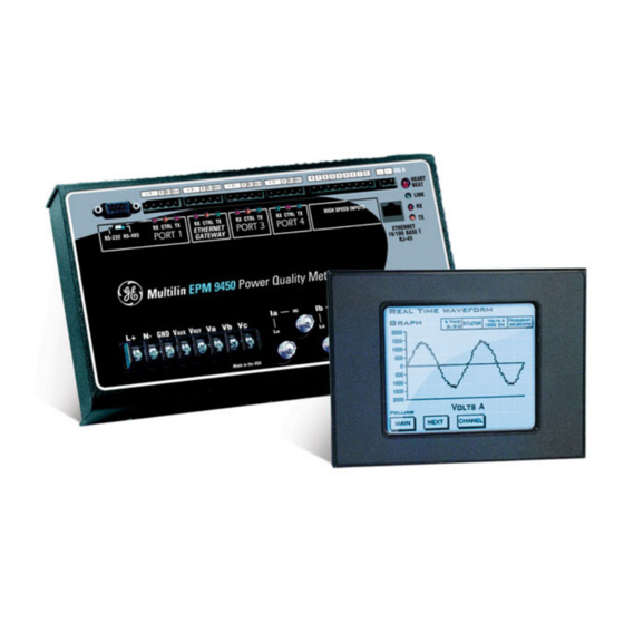
Grid Solutions EPM 9450/9650 Chapter 2: Meter Overview Meter Overview This chapter provides basic information on the EPM 9450/9650 meter. The EPM 9450/9650 System GE Digital Energy’s EPM 9450/9650 meter combines high-end revenue metering with sophisticated power quality analysis. Its advanced monitoring capabilities provide detailed PLUS and precise pictures of any metered point within a distribution network. -
Page 24: Flicker
DNP V.3.00 LEVEL 1 AND 2 CHAPTER 2: METER OVERVIEW • Offers inputs for neutral-to-ground voltage measurements • Synchronizes with IRIG-B or line frequency for clock synchronization • Measures Flicker (EPM 9650 only) • Offers EN50160/IEC 61000-4-15 logging and analysis (EPM 9650 with Software Option B only) EPM 9450/9650 Memory, Communication and Control •... -
Page 25: Comm Option 2: Internal Modem With Dial-In/Dial-Out Option
CHAPTER 2: METER OVERVIEW COMM OPTION 2: INTERNAL MODEM WITH DIAL-IN/DIAL-OUT OPTION Comm Option 2: Internal Modem with Dial-in/Dial-out Option The following sections describe the optional Comm Option 2 Internal Modem. 2.4.1 Hardware Overview Comm Option 2 for the EPM 9450/9650 meter provides a direct connection to a standard telephone line. -
Page 26: Total Web Solutions
TOTAL WEB SOLUTIONS CHAPTER 2: METER OVERVIEW Total Web Solutions The 10/100BaseT Ethernet Option (Comm Option 1) is a fully customizable web server that uses XML to provide access to real time data via any standard web browser. GE’s name for this dynamic system is Total Web Solutions. -
Page 27: Network Settings
CHAPTER 2: METER OVERVIEW TOTAL WEB SOLUTIONS 2.5.4 Network Settings Configure the Network Settings using the following steps (refer to the GE Communicator Instruction Manual for more details). From GE Communicator ‘s Main screen, click Profile to open the Device Profile screen. -
Page 28: Measurements And Calculations
MEASUREMENTS AND CALCULATIONS CHAPTER 2: METER OVERVIEW • Host: IP Address (per your network administrator). Example: 10.0.0.1 • Network Port: 502 • Protocol: Modbus TCP • Click the Connect button at the bottom of the screen. GE Communicator connects to the meter via the Network settings you entered. Measurements and Calculations The EPM 9450/9650 meter measures many different power parameters. - Page 29 CHAPTER 2: METER OVERVIEW MEASUREMENTS AND CALCULATIONS xy t Power (Watts) per phase: N = number of samples For Wye: x = a, b, c Apparent Power (VA) per phase: For Wye: x = a, b, c •...
- Page 30 MEASUREMENTS AND CALCULATIONS CHAPTER 2: METER OVERVIEW For Delta: ⎡ ⎤ ⎡ ∑ ∑ • • ⎢ ⎥ ⎢ ab t bc t ⎢ ⎥ ⎢ • ) − • ) − ⎢ ⎥ ⎢ ⎢ ⎥ ⎢ ⎣ ⎦ ⎣...
-
Page 31: Demand Integrators
CHAPTER 2: METER OVERVIEW DEMAND INTEGRATORS h RMS KFactor Watt hour (Wh): N = number of samples 3600 sec hr VAR hour (VARh): N = number of samples ... - Page 32 DEMAND INTEGRATORS CHAPTER 2: METER OVERVIEW Example: With settings of 3 five-minute subintervals, subinterval averages are computed every 5 minutes (12:00, 12:05, 12:15, etc.) for power readings over the previous five-minute interval (11:55-12:00, 12:00-12:05, 12:05-12:10, 12:10-12:15, etc.). In addition, every 5 minutes the subinterval averages are averaged in groups of 3 (12:00. 12:05, 12:10, 12:15.
- Page 33 CHAPTER 2: METER OVERVIEW DEMAND INTEGRATORS Partial Predict − Value − Value Partial − Value − × − × Partial ...
-
Page 34: Ordering
ORDERING CHAPTER 2: METER OVERVIEW Ordering 2.8.1 Order Codes The order codes for the Multilin™ 9450/9650 meter are shown below: Table 2–1: Multilin™ 9450/9650 order codes PL9450 – * – * – * – * – * Base unit PL9450 Power meter and data acquisition node System frequency 60 Hz frequency system... -
Page 35: Accessories
CHAPTER 2: METER OVERVIEW ORDERING Analog input modules: PL9000 – * – * – * – * – * – * – * – 0 – 0 Eight channel ±0 to 1 mA analog inputs Eight channel 4 to 20 mA analog inputs Eight channel ±0 to 5 VDC analog inputs Eight channel ±0 to 10 VDC analog inputs Digital output modules:... -
Page 36: Epm 9450/9650 Meter Specifications
EPM 9450/9650 METER SPECIFICATIONS CHAPTER 2: METER OVERVIEW EPM 9450/9650 Meter Specifications 2.9.1 Power Supply CONTROL POWER Option 0: ...........24VDC (-20%) to 48 VDC (+20%) Option 1: ...........120V AC/DC (-20%) to 230VAC (+20%) Connection Screws’ Torque: ..6 to 9 in-lb max. or 0.68 to 1 Nm max. Auxiliary Output Power Voltage:15 to 20VDC at 5-200mA Maximum Auxiliary Power Current:1A (short protected) Maximum Power Supply Range:100 to 250 VAC... -
Page 37: Environmental
CHAPTER 2: METER OVERVIEW EPM 9450/9650 METER SPECIFICATIONS 2.9.4 Environmental ENVIRONMENTAL RATING Operating: ........-40 to +70°C Humidity: ......... to 95% RH Non-condensing 2.9.5 Testing and certification COMPLIANCE Test Reference Standard Level/Class Electrostatic Discharge EN/IEC61000-4-2 Level 3 RF immunity EN/IEC61000-4-3 10V/m Fast Transient Disturbance EN/IEC61000-4-4... -
Page 38: Epm P40N Plus Led External Display Specifications
PLUS EPM P40N LED EXTERNAL DISPLAY SPECIFICATIONS CHAPTER 2: METER OVERVIEW PLUS 2.10 EPM P40N LED External Display Specifications Maximum Input Voltage:....30VDC Minimum Input Voltage: ....12VDC Maximum Power Consumption:5W Nominal Power Consumption:.Approximately 3W Operating Temperature Range: -20 to +70 C/-4 to +158 Overall Dimensions (HxWxD): .5.25 x 5.25 x1.79 inches/13.34 x 13.34 x 4.54 cm (The legacy P40N dimensions are 4.4 x 4.4 x 2.2 inches/11.1 x 11.1 x 5.9cm) -
Page 39: Mounting The Epm 9450/9650 Meter
Grid Solutions EPM 9450/9650 Chapter 3: Hardware Installation Hardware Installation This chapter provides installation information for the EPM 9450/9650 meter and its optional modules and displays. Mounting the EPM 9450/9650 Meter The EPM 9450/9650 Meter is designed to mount against any firm, flat surface. Use a #10 screw in each of the four slots on the flange to ensure that the unit is installed securely. - Page 40 MOUNTING THE EPM 9450/9650 METER CHAPTER 3: HARDWARE INSTALLATION • Relative Humidity: 5 to 95% non-condensing Figure 3-1: EPM 9450/9650 Mounting Diagram Top View 3–2 EPM 9450/9650 ADVANCED POWER QUALITY METERING SYSTEM – INSTRUCTION MANUAL...
- Page 41 CHAPTER 3: HARDWARE INSTALLATION MOUNTING THE EPM 9450/9650 METER Figure 3-2: EPM 9450/9650 Mounting Diagram Side View EPM 9450/9650 ADVANCED POWER QUALITY METERING SYSTEM – INSTRUCTION MANUAL 3–3...
-
Page 42: Mounting The Epm P40N Plus Led External Display
PLUS MOUNTING THE EPM P40N LED EXTERNAL DISPLAY CHAPTER 3: HARDWARE INSTALLATION PLUS Mounting the EPM P40N LED External Display The EPM 9450/9650 LED display (model number PL9000-P40NPLUS0) mounts using a standard ANSI C39.1 drill plan. Secure the four mounting studs to the back of the panel with the supplied nuts. Six feet of RS485 communication/power cable harness is supplied. -
Page 43: Mounting The Epm P60N Lcd External Display
CHAPTER 3: HARDWARE INSTALLATION MOUNTING THE EPM P60N LCD EXTERNAL DISPLAY Mounting the EPM P60N LCD External Display The EPM 9450/9650 touch-screen LCD display is available with either 6’ of cable (model number PL9000-P60N00000) or 15’ of cable (model number PL9000-P60N10000). The display can be mounted up to 50 feet from the meter using the meter’s internal power supply. - Page 44 MOUNTING THE EPM P60N LCD EXTERNAL DISPLAY CHAPTER 3: HARDWARE INSTALLATION Cut an opening in the mounting panel. Follow cutout dimensions shown. Carefully “drop in” the display with bezel and gasket attached. Fasten the unit securely with the four 6-32 hex nuts supplied. 3–6 EPM 9450/9650 ADVANCED POWER QUALITY METERING SYSTEM –...
-
Page 45: Mounting The Epm External I/O Modules
CHAPTER 3: HARDWARE INSTALLATION MOUNTING THE EPM EXTERNAL I/O MODULES Mounting the EPM External I/O Modules A mounting bracket kit (p/n PL9000-MBIO) is required in order to install the I/O modules, and must be ordered separately. Order one mounting bracket kit per module group. Each mounting bracket kit includes mounting brackets, screws, and a cable. - Page 46 MOUNTING THE EPM EXTERNAL I/O MODULES CHAPTER 3: HARDWARE INSTALLATION Mounting Brackets (MBIO) Female RS485 Side Port I/O Port (Size and Pin Male RS485 Configuration Vary) Side Port Figure 3-7: I/O Module Communication Ports and Mounting Brackets Figure 3-8: I/O Modules Mounting Diagram Front View 3–8 EPM 9450/9650 ADVANCED POWER QUALITY METERING SYSTEM –...
-
Page 47: Considerations When Installing Meters
Grid Solutions EPM 9450/9650 Chapter 4: Electrical Installation Electrical Installation This chapter provides electrical installation information for the EPM 9450/9650 meter. Considerations When Installing Meters Installation of the EPM 9450/9650 meter must be performed only by qualified personnel who follow standard safety precautions during all procedures. Those personnel should have appropriate training and experience with high voltage devices. - Page 48 CONSIDERATIONS WHEN INSTALLING METERS CHAPTER 4: ELECTRICAL INSTALLATION To comply with UL standards, the meter case must be connected to a reliable protective earth available within the installation area. For this connection use minimum #14 AWG wire crimped to a ring terminal (3) with a dedicated tool. Fasten the ring terminal (3) to the lower left slot of the meter case with minimum #6 metal screw(1) and star washer (2), as is shown in Figure 4.1.
-
Page 49: Wiring The Monitored Inputs And Voltages
CHAPTER 4: ELECTRICAL INSTALLATION WIRING THE MONITORED INPUTS AND VOLTAGES Wiring the Monitored Inputs and Voltages Select a wiring diagram from Section 4.5 that best suits your application. Wire the EPM 9450/9650 meter exactly as shown. For proper operation, the voltage connection must be maintained and must correspond to the correct terminal. -
Page 50: Isolating A Ct Connection Reversal
ISOLATING A CT CONNECTION REVERSAL CHAPTER 4: ELECTRICAL INSTALLATION CT size (VA) Maximum Distance from CT to EPM Meter (Ft) DO NOT leave the secondary of the CT open when primary current is flowing. This may cause high voltage, which will overheat the CT. If the CT is not connected, provide a shorting block on the secondary of the CT. -
Page 51: Instrument Power Connections
CHAPTER 4: ELECTRICAL INSTALLATION INSTRUMENT POWER CONNECTIONS Instrument Power Connections The EPM 9450/9650 meter requires a separate power source. To use AC power: Connect the line supply wire to the L+ terminal Connect the neutral supply wire to the N- terminal on the meter. To use DC power: Connect the positive supply wire to the L+ terminal. -
Page 52: Wiring Diagrams
WIRING DIAGRAMS CHAPTER 4: ELECTRICAL INSTALLATION Wiring Diagrams Choose the diagram that best suits your application. Diagrams appear on the following pages. If the connection diagram you need is not shown, contact GE for a custom Connection diagram. If you purchased a system voltage option "B" EPM 9450/9650 meter for a 300 Volt Note secondary, be sure to enable the option on the CT and PT screen of the GE Communicator software's Device Profile (see the GE Communicator Instruction Manual for instructions). - Page 53 CHAPTER 4: ELECTRICAL INSTALLATION WIRING DIAGRAMS Figure 4-2: 4-Wire Wye, 3-Element Direct Voltage with 4 CTs EPM 9450/9650 ADVANCED POWER QUALITY METERING SYSTEM – INSTRUCTION MANUAL 4–7...
- Page 54 WIRING DIAGRAMS CHAPTER 4: ELECTRICAL INSTALLATION Figure 4-3: 4-Wire Wye, 3-Element with 3 PTs and 4 CTs 4–8 EPM 9450/9650 ADVANCED POWER QUALITY METERING SYSTEM – INSTRUCTION MANUAL...
- Page 55 CHAPTER 4: ELECTRICAL INSTALLATION WIRING DIAGRAMS Figure 4-4: 4-Wire Wye, 3-Element with 3 PTs and 3 CTs EPM 9450/9650 ADVANCED POWER QUALITY METERING SYSTEM – INSTRUCTION MANUAL 4–9...
- Page 56 WIRING DIAGRAMS CHAPTER 4: ELECTRICAL INSTALLATION Figure 4-5: 3-Wire, 2-Element Open Delta with 2 PTs and 3 CTs 4–10 EPM 9450/9650 ADVANCED POWER QUALITY METERING SYSTEM – INSTRUCTION MANUAL...
- Page 57 CHAPTER 4: ELECTRICAL INSTALLATION WIRING DIAGRAMS Figure 4-6: 3-Wire, 2-Element Open Delta with 2 PTs and 2 CTs EPM 9450/9650 ADVANCED POWER QUALITY METERING SYSTEM – INSTRUCTION MANUAL 4–11...
- Page 58 WIRING DIAGRAMS CHAPTER 4: ELECTRICAL INSTALLATION Figure 4-7: 3-Wire, 2-Element Delta Direct Voltage with 3 CTs 4–12 EPM 9450/9650 ADVANCED POWER QUALITY METERING SYSTEM – INSTRUCTION MANUAL...
- Page 59 CHAPTER 4: ELECTRICAL INSTALLATION WIRING DIAGRAMS Figure 4-8: 3-Phase, 4-Wire, 2.5 Element with 2 PTs and 3 CTs EPM 9450/9650 ADVANCED POWER QUALITY METERING SYSTEM – INSTRUCTION MANUAL 4–13...
- Page 60 WIRING DIAGRAMS CHAPTER 4: ELECTRICAL INSTALLATION Figure 4-9: 4-Wire, 3-Element Grounded Delta with 4 CTs - B Option 4–14 EPM 9450/9650 ADVANCED POWER QUALITY METERING SYSTEM – INSTRUCTION MANUAL...
- Page 61 Grid Solutions EPM 9450/9650 Chapter 5: Communication Wiring Communication Wiring This chapter provides wiring information for the EPM 9450/9650 meter’s communication options. Communication Overview RS232 communication is used to connect a single EPM 9450/9650 meter with another device, such as a computer, RTU or PLC. The link is viable for a distance of up to 50 feet (15.2 meters) and is available only through the meter’s Port 1.
-
Page 62: 5: Communication Communication Overview
COMMUNICATION OVERVIEW CHAPTER 5: COMMUNICATION WIRING RJ11 Telephone Line allows a EPM 9450/9650 meter with an Internal Modem (Comm Option 2) to communicate with a PC. No other hardware is necessary for this easy-to-use connection. For more details, see Chapter 10. Figure 5-1: RJ11 Communication with Internal Modem Option RJ45 Network Connection allows a EPM 9450/9650 meter with the Internal Network Option (Comm Option 1) to communicate with multiple PC’s simultaneously. - Page 63 CHAPTER 5: COMMUNICATION WIRING COMMUNICATION OVERVIEW Figure 5-2: RJ45 Communication with Internal Network Option EPM 9650 meters can also communicate with DNP 3.0 protocol over Ethernet. Note EPM 9450/9650 ADVANCED POWER QUALITY METERING SYSTEM – INSTRUCTION MANUAL 5–3...
- Page 64 COMMUNICATION OVERVIEW CHAPTER 5: COMMUNICATION WIRING + - S -V+ + - S -V+ + + G ~120 Ohms ~120 Ohms ~120 Ohms RS232 Extension Cable 1:1 Wiring 120 Ohms ~120 Ohms ~120 Ohms 8 7 6 5 4 3 2 1 0 +V- S - + +V- S - + +V- S - + +V- S - +...
-
Page 65: Rs232 Connection (Port 1)
CHAPTER 5: COMMUNICATION WIRING RS232 CONNECTION (PORT 1) RS232 Connection (Port 1) • Use Port 1 for RS232 communication. Set the selector switch beneath the port to RS232. • Insert one end of an RS232 extension cable into the EPM 9450/9650 meter’s 9-pin female serial port. -
Page 66: Rs485 Communication
RS485 COMMUNICATION CHAPTER 5: COMMUNICATION WIRING RS485 Communication RS485 communication allows multiple devices to communicate on a bus. The EPM 9450/ 9650 meter’s Ports 1 to 4 are RS485 terminals, viable for a distance of up to 4000 feet (1219 meters). (Port 1 can be switched between RS232 and RS485.) The following figure shows wiring detail of a 2-wire RS485 port. -
Page 67: Rs485 Connection
CHAPTER 5: COMMUNICATION WIRING RS485 COMMUNICATION Slave device 1 Long stub results “T” connection that can cause interference problem! Master device Last Slave device N Slave device 2 Twisted pair, shielded (SH) cable Twisted pair, shielded (SH) cable Twisted pair, shielded (SH) cable Earth Connection, preferably at single location Twisted pair, shielded (SH) cable... -
Page 68: Rs485 Connection To The Epm P40Nplus Or P60N External Display
RS485 COMMUNICATION CHAPTER 5: COMMUNICATION WIRING • Connect the shield to the Ground (G) terminal on the Master. The (S) terminal on the EPM meter is used to reference the EPM meter’s port to the same potential as the source. It is not an earth-ground connection. You must also connect the shield to earth-ground at one point. -
Page 69: Rj11 (Telephone Line) Connection-Epm Meter With Internal Modem Option (Comm Option 2) To A Pc
CHAPTER 5: COMMUNICATION WIRING RJ11 (TELEPHONE LINE) CONNECTION—EPM METER WITH INTERNAL MODEM OPTION (COMM OPTION 2) TO A PC RJ11 (Telephone Line) Connection—EPM Meter with Internal Modem Option (Comm Option 2) to a PC Use RJ11 Standard Telephone Line to connect with the EPM 9450/9650 meter. For details on this connection, see Chapter 10. -
Page 70: Steps To Determine Power Needed
COMMUNICATION PORTS ON THE EPM I/O MODULES CHAPTER 5: COMMUNICATION WIRING • Insert the other end of the cable into the I/O module’s female RS485 side port (see Figure 5.8). The connectors fit only one way into the ports. • Use the male RS485 side port to attach another I/O module. The EPM 9450/9650 meter can power up to four connected I/O modules using 15–20V DC at 50–... -
Page 71: Linking Multiple Epm Meters In Series
CHAPTER 5: COMMUNICATION WIRING LINKING MULTIPLE EPM METERS IN SERIES As the table above shows, all I/O modules are shipped pre-programmed with a baud rate of 57600 and addresses. For programming instructions, refer to the GE Communicator Instruction Manual. See the next page for the external displays’ VA Ratings. If you are using a PSIO (for 125V AC/DC input) your maximum VA is 12. -
Page 72: Remote Communication-Rs232
REMOTE COMMUNICATION OVERVIEW CHAPTER 5: COMMUNICATION WIRING Either RJ11 (Comm Option 2) or RJ45 (Comm Option 1) can connect devices at great distances. Section 5.1 gives an overview of these communication options. Chapter 10 explains the Comm 2 Internal Modem Option; Chapter 11 explains the Comm 1 Network Option. -
Page 73: Programming Modems For Remote Communication
CHAPTER 5: COMMUNICATION WIRING REMOTE COMMUNICATION OVERVIEW 5.8.3 Programming Modems for Remote Communication You must program a modem before it can communicate properly with most RS485 or RS232-based devices. This task is often quite complicated because modems can be unpredictable when communicating with remote devices. You must set the following strings to communicate with the remote EPM meter(s). - Page 74 REMOTE COMMUNICATION OVERVIEW CHAPTER 5: COMMUNICATION WIRING Modem String/Setting USRobotics Sportster 56K AT&F0&W0Y0 Faxmodem: DIP switch setting Up Up Down Down Up Up Up Down 5–14 EPM 9450/9650 ADVANCED POWER QUALITY METERING SYSTEM – INSTRUCTION MANUAL...
-
Page 75: High Speed Inputs Connection
CHAPTER 5: COMMUNICATION WIRING HIGH SPEED INPUTS CONNECTION High Speed Inputs Connection The EPM 9450/9650 meter’s built-in High Speed Inputs can be used in many ways: • Attach the KYZ HS Outputs from other meters for totalizing. • Attach relaying contacts for breaker status or initiated logging. •... -
Page 76: Irig-B Connections
IRIG-B CONNECTIONS CHAPTER 5: COMMUNICATION WIRING 5.10 IRIG-B Connections IRIG-B is a standard time code format that synchronizes event time-stamping to within 1 millisecond. An IRIG-B signal-generating device connected to the GPS satellite system synchronizes EPM 9450/9650 meters located at different geographic locations. EPM meters use an un-modulated signal from a satellite-controlled clock (such as the GE MultiSync 1588). - Page 77 CHAPTER 5: COMMUNICATION WIRING IRIG-B CONNECTIONS Troubleshooting Tip: The most common source of problems is a reversal of the two wires. If you have a problem, try reversing the wires. IRIG-B Port IRIG-B Time Signal Generating Device Figure 5-12: IRIG-B Communication Please make sure that the selected clock can drive the amount of wired loads.
-
Page 78: Time Synchronization Alternatives
TIME SYNCHRONIZATION ALTERNATIVES CHAPTER 5: COMMUNICATION WIRING 5.11 Time Synchronization Alternatives (See the GE Communicator Instruction Manual for details.) IRIG-B • All EPM 9450/9650 meters are equipped to use IRIG-B for time synchronization. • If IRIG-B is connected, this form of time synchronization takes precedence over the internal clock. -
Page 79: Overview
Grid Solutions EPM 9450/9650 Chapter 6: Using the External Displays Using the External Displays This chapter provides information on the EPM 9450/9650 meter’s external displays. Overview GE offers two external displays for use with the EPM 9450/9650 meter: • EPM P60N LCD Display PLUS •... -
Page 80: Using The Epm P60N Lcd External Display
USING THE EPM P60N LCD EXTERNAL DISPLAY CHAPTER 6: USING THE EXTERNAL DISPLAYS Using the EPM P60N LCD External Display The EPM P60N LCD external display has a programmable address, allowing access to up to 8 meters. The Touch Screen External Display is ready to use upon power-up. Touching the “buttons” at the top of the screen will take you to the Groups of Readings listed in section 6.2.2. -
Page 81: Epm P60N Display Groups Of Readings
CHAPTER 6: USING THE EXTERNAL DISPLAYS USING THE EPM P60N LCD EXTERNAL DISPLAY The screens available on the EPM P60N LCD display depend on the features and Software Note options of the attached EPM 9450/9650 meter. See section 6.2.3 for a full navigational map of all available options. - Page 82 USING THE EPM P60N LCD EXTERNAL DISPLAY CHAPTER 6: USING THE EXTERNAL DISPLAYS DEMAND POWER: Demand Power Readings Details R/T button goes to Real Time Power screen. • Thermal Window Average Maximum +kWatt/+kVAR/CoIn kVAR • Fixed Window Average Maximum +kWatt/+kVAR/CoIn kVAR •...
- Page 83 CHAPTER 6: USING THE EXTERNAL DISPLAYS USING THE EPM P60N LCD EXTERNAL DISPLAY TOU: Register Demand/ Register 1 - 8 Accum button goes to TOU Register Accumulation screen. Next Reg button displays Registers 1 - 8. Next Group button displays Prior Season, Month, Current Season, Month.
- Page 84 USING THE EPM P60N LCD EXTERNAL DISPLAY CHAPTER 6: USING THE EXTERNAL DISPLAYS FLICKER: Long Term Instantaneous button goes to Flicker - Instantaneous screen. Short Term button goes to Flicker - Short Term screen. • Current Plt values for Va, Vb, Vc, and the time of computation •...
- Page 85 CHAPTER 6: USING THE EXTERNAL DISPLAYS USING THE EPM P60N LCD EXTERNAL DISPLAY SPECTRUM: Harmonic Spectrum Analysis Use Channel button to view graphs and readings: Zoom In or Out for detail. • Channel Van/bn/cn • Channel Ia/b/c • % THD, KFactor, Frequency for selected channel TREND: Real Time Trending Analysis Use Channel button to view different graphs...
- Page 86 USING THE EPM P60N LCD EXTERNAL DISPLAY CHAPTER 6: USING THE EXTERNAL DISPLAYS EPM P60N Display Settings LCD Screen Settings: • Contrast - Touch Up/Down buttons to increase/decrease settings. A Contrast of 37 is the optimum setting. • Backlight Off Delay - number of seconds after use that backlight turns off.
- Page 87 CHAPTER 6: USING THE EXTERNAL DISPLAYS USING THE EPM P60N LCD EXTERNAL DISPLAY Firmware Versions: Meter versions: • Boot • Run-time • DSP Boot • DSP Run-time LCD Display version This screen displays the current firmware version for the Meter and the display. EPM 9450/9650 ADVANCED POWER QUALITY METERING SYSTEM –...
-
Page 88: Epm P60N Display Navigational Map (All Options)
USING THE EPM P60N LCD EXTERNAL DISPLAY CHAPTER 6: USING THE EXTERNAL DISPLAYS 6.2.2 EPM P60N Display Navigational Map (all options) 6–10 EPM 9450/9650 ADVANCED POWER QUALITY METERING SYSTEM – INSTRUCTION MANUAL... -
Page 89: Using The Epm P40Nplus Led External Display
CHAPTER 6: USING THE EXTERNAL DISPLAYS USING THE EPM P40NPLUS LED EXTERNAL DISPLAY PLUS Using the EPM P40N LED External Display PLUS 6.3.1 Using the EPM P40N USB port PLUS The EPM P40N LED external display has a USB port on the front for direct data downloads. - Page 90 USING THE EPM P40NPLUS LED EXTERNAL DISPLAY CHAPTER 6: USING THE EXTERNAL DISPLAYS Connect the USB cable from your PC to the port: using a USA-A Male to USB-B Male cable, attach the USB-A connector to the PC and attach the USB-B PLUS connector to the P40N USB port.
- Page 91 CHAPTER 6: USING THE EXTERNAL DISPLAYS USING THE EPM P40NPLUS LED EXTERNAL DISPLAY • Click the Hardware tab. You will see the screen below. • Click the Device Manager button. You will see a list of the computer's hardware devices. •...
-
Page 92: Connect Multiple Displays
USING THE EPM P40NPLUS LED EXTERNAL DISPLAY CHAPTER 6: USING THE EXTERNAL DISPLAYS Open GE Communicator software and click the Connect icon in the Icon bar. See the screen shown below. Click the Serial Port button if it’s not already selected. Set the Baud Rate to 9600. -
Page 93: Epm P40Nplus Dynamic Readings Mode
CHAPTER 6: USING THE EXTERNAL DISPLAYS USING THE EPM P40NPLUS LED EXTERNAL DISPLAY • Use the UP/DOWN arrows to scroll from group to group within each mode. • Use the LEFT/RIGHT arrows to scroll from reading to reading within each group. PLUS Use the GE Communicator software to Flash Update the P40N external display. - Page 94 USING THE EPM P40NPLUS LED EXTERNAL DISPLAY CHAPTER 6: USING THE EXTERNAL DISPLAYS • Maximum kVA/Hz • Minimum kVA/Hz • Maximum Quadrant 1 Total PF • Minimum Quadrant 1 Total PF • Maximum Quadrant 2 Total PF • Minimum Quadrant 2 Total PF •...
- Page 95 CHAPTER 6: USING THE EXTERNAL DISPLAYS USING THE EPM P40NPLUS LED EXTERNAL DISPLAY • Use Up/Down arrows to scroll between groups. Max %THD Min %THD Return to 1 Second Volts Maximum Volts Minimum Volts %THD Volts Volts Volts First AN,BN,CN AN,BN,CN AN,BN,CN AN,BN,CN...
-
Page 96: Mode
USING THE EPM P40NPLUS LED EXTERNAL DISPLAY CHAPTER 6: USING THE EXTERNAL DISPLAYS PLUS 6.3.5 EPM P40N Information Mode Use the Mode button to access the EPM Information mode from other modes. Use the Up/ Down arrows to navigate from group to group within this mode. Group 1: Device Time Meter Time Group 2: Communication Settings (Use the Left/Right arrows to access the following... - Page 97 CHAPTER 6: USING THE EXTERNAL DISPLAYS USING THE EPM P40NPLUS LED EXTERNAL DISPLAY Navigation Map of EPM Information Mode • Use Left/Right arrow keys to navigate Readings • Use Up/Down arrows to scroll between groups. Meter Time Comm Return Comm Comm Comm Settings...
-
Page 98: Display Features Mode
USING THE EPM P40NPLUS LED EXTERNAL DISPLAY CHAPTER 6: USING THE EXTERNAL DISPLAYS 6.3.6 Display Features Mode Use the Mode button to access the Display Features Mode from other modes. Use the Up/ Down arrows to navigate from group to group within this mode. Group 1: Reset Max/Min Press Enter to reset the Max and Min values. - Page 99 CHAPTER 6: USING THE EXTERNAL DISPLAYS USING THE EPM P40NPLUS LED EXTERNAL DISPLAY Navigation Map of Display Features Mode Use Up/Down arrows to scroll between groups. Reset Max/Min Reset Energy Baud Rate/Address Communication Protocol Lamp Test Display Scroll On/Off EPM 9450/9650 ADVANCED POWER QUALITY METERING SYSTEM – INSTRUCTION MANUAL 6–21...
- Page 100 USING THE EPM P40NPLUS LED EXTERNAL DISPLAY CHAPTER 6: USING THE EXTERNAL DISPLAYS 6–22 EPM 9450/9650 ADVANCED POWER QUALITY METERING SYSTEM – INSTRUCTION MANUAL...
- Page 101 Grid Solutions EPM 9450/9650 Chapter 7: Transformer Loss Compensation Transformer Loss Compensation Introduction The Edison Electric Institute's Handbook for Electricity Metering, Ninth Edition defines Loss Compensation as: A means for correcting the reading of a meter when the metering point and point of service are physically separated, resulting in measurable losses including I2R losses in conductors and transformers and iron-core losses.
- Page 102 INTRODUCTION CHAPTER 7: TRANSFORMER LOSS COMPENSATION The need for loss compensated metering may also exist when the ownership changes several miles along a transmission line where it is simply impractical to install metering equipment. Ownership may change at the midway point of a transmission line where there are no substation facilities.
- Page 103 CHAPTER 7: TRANSFORMER LOSS COMPENSATION INTRODUCTION "subtracted from" (depending on whether add or subtract is selected) the Received Power flow. For example, if losses are set to "Add to" and received power equals 2000 kW and losses are equal to 20kW then the total metered value with loss compensation would be 2020 kW;...
-
Page 104: Loss Compensation In Three Element Installations
EPM 9450/9650 METER'S TRANSFORMER LOSS COMPENSATION CHAPTER 7: TRANSFORMER LOSS COMPENSATION EPM 9450/9650 Meter's Transformer Loss Compensation The EPM 9450/9650 meter provides compensation for active and reactive power quantities by performing numerical calculations. The factors used in these calculations are derived either: •... - Page 105 CHAPTER 7: TRANSFORMER LOSS COMPENSATION EPM 9450/9650 METER'S TRANSFORMER LOSS COMPENSATION Correct calculation of loss compensation also requires knowledge of the meter installation. In order to calculate the loss compensation settings you will need the following information regarding the meter and the installation: •...
- Page 106 EPM 9450/9650 METER'S TRANSFORMER LOSS COMPENSATION CHAPTER 7: TRANSFORMER LOSS COMPENSATION Enter 3-Phase or 1-Phase values. If 3-Phase values are entered, calculate 1-Phase values by dividing 3-Phase values by three. Convert 1-Phase Self-Cooled MVA to 1-Phase kVA by multiplying by 1000. % Exciting Current % Impedance Value...
- Page 107 CHAPTER 7: TRANSFORMER LOSS COMPENSATION EPM 9450/9650 METER'S TRANSFORMER LOSS COMPENSATION TrfIT Secondary is the Base Value of Voltage and Current at the Instrument Transformer Secondary of the Power Transformer. These numbers are obtained by dividing the Transformer Voltage and Current by their respective Multipliers. The Meter/Trf values for Voltage and Current are obtained by dividing the Meter Base values by the TrfIT Secondary values.
- Page 108 EPM 9450/9650 METER'S TRANSFORMER LOSS COMPENSATION CHAPTER 7: TRANSFORMER LOSS COMPENSATION Enter Value at Transformer Base for each quantity from calculations above. Enter Meter/ Trf Factor value from Base Conversion Factor calculations above. Calculate M/T Factor with Exponent by raising the M/T Factor to the power indicated in the "Exp" (or Exponent) column.
- Page 109 Grid Solutions EPM 9450/9650 Chapter 8: Time-of-Use Function Time-of-Use Function Introduction A Time-of-Use (TOU) usage structure takes into account the quantity of energy used and the time at which it was consumed. The EPM 9450/9650 meter's TOU function, available with the GE Communicator software, is designed to accommodate a variety of programmable rate structures.
-
Page 110: Tou Prior Season And Month
THE EPM 9450/9650 METER'S TOU CALENDAR CHAPTER 8: TIME-OF-USE FUNCTION The EPM 9450/9650 Meter's TOU Calendar A EPM TOU calendar sets the parameters for TOU data accumulation. You may store up to twenty calendars in the EPM 9450/9650 meter and an unlimited amount of calendar files on your computer. -
Page 111: Updating, Retrieving And Replacing Tou Calendars
CHAPTER 8: TIME-OF-USE FUNCTION UPDATING, RETRIEVING AND REPLACING TOU CALENDARS Updating, Retrieving and Replacing TOU Calendars GE Communicator software retrieves TOU calendars from the EPM 9450/9650 meter or from the computer's hard drive for review and edit. Up to a maximum of twenty yearly calendars can be stored in the EPM 9450/9650 meter at any given time. - Page 112 DAYLIGHT SAVINGS AND DEMAND CHAPTER 8: TIME-OF-USE FUNCTION 8–4 EPM 9450/9650 ADVANCED POWER QUALITY METERING SYSTEM – INSTRUCTION MANUAL...
- Page 113 Grid Solutions EPM 9450/9650 Chapter 9: External I/O Modules External I/O Modules Hardware Overview All EPM External I/O modules have the following components: • Female RS485 Side Port: use to connect to another module’s male RS485 side port. • Male RS485 Side Port: use to connect to the EPM 9450/9650 Meter’s Port 3 or 4 or to another module’s female RS485 side port.
-
Page 114: Port Overview
HARDWARE OVERVIEW CHAPTER 9: EXTERNAL I/O MODULES • Mounting Brackets (MBIO): used to secure one or more modules to a flat surface. Figure 9-1: I/O Module Components 9.1.1 Port Overview All GE I/O Modules have ports through which they interface with other devices. The port configurations are variations of the four types shown below. - Page 115 CHAPTER 9: EXTERNAL I/O MODULES HARDWARE OVERVIEW Eight Analog Inputs Four Relay Outputs (0-1mA, 0-20mA, 0-5Vdc, or Four KYZ Pulse Outputs 0-10Vdc) or Eight Status Inputs 0-1mA Analog Input Module INPUT 1 INPUT 2 INPUT 3 INPUT 4 INPUT 5 INPUT 6 INPUT 7 INPUT 8...
-
Page 116: I/O Module Installation
I/O MODULE INSTALLATION CHAPTER 9: EXTERNAL I/O MODULES I/O Module Installation See sections 3.3 and 5.6 for installation instructions for the external I/O Modules. 9.2.1 Power Source for I/O Modules The EPM 9450/9650 can supply power to a limited number of I/O Modules and external displays. - Page 117 CHAPTER 9: EXTERNAL I/O MODULES I/O MODULE INSTALLATION Figure 9-4: PSIO Side and Top Labels (Labels are Red and White) EPM 9450/9650 ADVANCED POWER QUALITY METERING SYSTEM – INSTRUCTION MANUAL 9–5...
-
Page 118: Using The Psio With Multiple I/O Modules
USING THE PSIO WITH MULTIPLE I/O MODULES CHAPTER 9: EXTERNAL I/O MODULES Using the PSIO with Multiple I/O Modules Female Mounting RS485 bracket side Port Figure 9-5: PSIO Used with Multiple I/O Modules As shown, the PSIO must be to the right of I/O Modules when viewing the side label. Note 9.3.1 Steps for Attaching Multiple I/O Modules... - Page 119 CHAPTER 9: EXTERNAL I/O MODULES USING THE PSIO WITH MULTIPLE I/O MODULES 10. The MBIO mounting brackets kit comes with 2 DIN rail mounting clips and an 8mm screw and lock washer for each clip. The clips let you easily mount the connected I/O modules (or a single I/O module between two brackets) on a DIN rail.
-
Page 120: Factory Settings And Reset Button
FACTORY SETTINGS AND RESET BUTTON CHAPTER 9: EXTERNAL I/O MODULES Factory Settings and Reset Button Factory Settings: All EPM I/O Modules are shipped with a preset address and a baud rate of 57600. See the following sections for I/O Module addresses. Default Settings: Sometimes a problem prevents an I/O module from running in its Normal mode. -
Page 121: Analog Transducer Signal Output Modules
CHAPTER 9: EXTERNAL I/O MODULES ANALOG TRANSDUCER SIGNAL OUTPUT MODULES Analog Transducer Signal Output Modules Table 0 Analog Transducer Signal Output Module Specifications Model Numbers 1mAON4: 4-channel analog output 0 ±1mA 1mAON8: 8-channel analog output 0 ±1mA 20mAON4: 4-channel analog output 4 to 20mA 20mAON8: 8-channel analog output 4 to 20mA Accuracy 0.1% of Full Scale... -
Page 122: Normal Mode
ANALOG TRANSDUCER SIGNAL OUTPUT MODULES CHAPTER 9: EXTERNAL I/O MODULES 9.5.2 Normal Mode Normal Mode is the same for the 0-1mA and the 4-20mA Analog Output Modules except for the number of processes performed by the modules. Both devices: Accept new values through communication. Output current loops scaled from previously accepted values. -
Page 123: Analog Input Modules
CHAPTER 9: EXTERNAL I/O MODULES ANALOG INPUT MODULES Analog Input Modules Table 0 Analog Input Module Specifications Model Numbers 8AI1: 8-channel analog input 0 ±1mA 8AI2: 8-channel analog input 4-20mA 8AI3: 8-channel analog input 0 ±5VDC 8AI4: 8-channel analog input 0 ±10VDC Accuracy 0.1% of Full Scale Scaling... -
Page 124: Normal Mode
DIGITAL DRY CONTACT RELAY OUTPUT (FORM C) MODULE CHAPTER 9: EXTERNAL I/O MODULES 9.6.2 Normal Mode In Normal Mode, the Input Module: Reads and averages the A/D and adjusts values for process 2. Calculates the percentage of Input Value. The percentage value of the Input is stored in Input Value Registers (Registers 04097- Note 04104). -
Page 125: O Verview
CHAPTER 9: EXTERNAL I/O MODULES DIGITAL SOLID STATE PULSE OUTPUT (KYZ) MODULE 9.7.1 Overview The Relay Output Module consists of four Latching Relay Outputs. In Normal Mode, the device accepts commands to control the relays. Relay output modules are triggered by limits programmed with the GE Communicator software. See the GE Communicator Instruction Manual for details on programming limits. -
Page 126: O Verview
DIGITAL SOLID STATE PULSE OUTPUT (KYZ) MODULE CHAPTER 9: EXTERNAL I/O MODULES Digital Solid State Pulse Output Module Specifications Factory Settings Modbus Address: 160 Baud Rate: 57600 Transmit Delay Time: 0 Default Settings (Reset Modbus Address: 247 Button) Baud Rate: 57600 Transmit Delay Time: 20msec 9.8.1 Overview... -
Page 127: Digital Status Input Module
CHAPTER 9: EXTERNAL I/O MODULES DIGITAL STATUS INPUT MODULE then replaced with the new value. Attempting to write a value greater than the programmed Rollover Value for a given channel is completely ignored and no registers are modified. If the difference is greater than half of the programmed Rollover Value for a given channel, the write does not increment the Residual but does update the Last Value. -
Page 128: O Verview
DIGITAL STATUS INPUT MODULE CHAPTER 9: EXTERNAL I/O MODULES Digital Status Input Module Specifications Factory Settings Modbus Address: 164 Baud Rate: 57600 Transmit Delay Time: 0 Default Settings (Reset Button) Modbus Address: 247 Baud Rate: 57600 Transmit Delay Time: 20msec 9.9.1 Overview The Digital Status Input Module is used either for additional status detect or for... - Page 129 Grid Solutions EPM 9450/9650 Chapter 10: Meter with Internal Modem Option (Comm Option 2) Meter with Internal Modem Option (Comm Option 2) 10.1 Hardware Overview The EPM 9450/9650 meter with the Comm 2, Internal Modem Option, has all the components of the standard EPM meter plus the capability of connecting to a PC via a standard phone line.
-
Page 130: Dial-In Function
HARDWARE CONNECTION CHAPTER 10: METER WITH INTERNAL MODEM OPTION (COMM OPTION 2) 10.2 Hardware Connection Use RJ11 Standard Telephone Line to connect with the EPM 9450/9650 meter. Insert the RJ11 line into the RJ11 Port on the face of an EPM 9450/9650 meter with the Internal Modem Option. -
Page 131: Dial-Out Function
CHAPTER 10: METER WITH INTERNAL MODEM OPTION (COMM OPTION 2) DIAL-OUT FUNCTION 10.4 Dial-Out Function The Dial-Out Function enabled by Comm Option 2 allows the meter to automatically report certain conditions without direct user oversight. The modem normally polls the meter to determine if any abnormal or reportable conditions exist, such as those in the following list. - Page 132 DIAL-OUT FUNCTION CHAPTER 10: METER WITH INTERNAL MODEM OPTION (COMM OPTION 2) 10–4 EPM 9450/9650 ADVANCED POWER QUALITY METERING SYSTEM – INSTRUCTION MANUAL...
-
Page 133: 11: Meter With Optional Internal Network (Comm Option 1)
Grid Solutions EPM 9450/9650 Chapter 11: Meter with Optional Internal Network (Comm Option 1) Meter with Optional Internal Network (Comm Option 1) 11.1 Hardware Overview The EPM 9450/9650 meter with the Internal Network Option (Comm Option 1) has all the components of the standard EPM 9450/9650 meter, plus giving you the capability of connecting to multiple PC’s via Modbus/TCP over the Ethernet and providing a DNP LAN/ WAN connection. - Page 134 HARDWARE OVERVIEW CHAPTER 11: METER WITH OPTIONAL INTERNAL NETWORK (COMM OPTION 1) Figure 11-1: Meter Communication with Network Option/Daisy Chained Meters The Internal Network Option of the EPM 9450/9650 meter is an extremely versatile communications tool. The Internal Network Option: •...
- Page 135 CHAPTER 11: METER WITH OPTIONAL INTERNAL NETWORK (COMM OPTION 1) NETWORK CONNECTION 11.2 Network Connection Use Standard RJ45 10/100BaseT cable to connect with the EPM 9450/9650 meter. Insert the RJ45 line into the RJ45 Port on the face of a EPM 9450/9650 meter with the Internal Network Option.
- Page 136 NETWORK CONNECTION CHAPTER 11: METER WITH OPTIONAL INTERNAL NETWORK (COMM OPTION 1) 11–4 EPM 9450/9650 ADVANCED POWER QUALITY METERING SYSTEM – INSTRUCTION MANUAL...
-
Page 137: 12: Flicker And Analysis
Grid Solutions EPM 9450/9650 Chapter 12: Flicker and Analysis Flicker and Analysis 12.1 Overview Flicker is the sensation that is experienced by the human visual system when it is subjected to changes occurring in the illumination intensity of light sources. The primary effects of Flicker are headaches, irritability and, sometimes, epileptic seizures. -
Page 138: Theory Of Operation
THEORY OF OPERATION CHAPTER 12: FLICKER AND ANALYSIS 12.2 Theory of Operation Flicker can be caused by voltage variations that are in turn caused by variable loads, such as arc furnaces, laser printers and microwave ovens. In order to model the eye brain change, which is a complex physiological process, the signal from the power network has to be processed while conforming with Figure 12.1, shown on page 12-4. -
Page 139: S Ummary
CHAPTER 12: FLICKER AND ANALYSIS THEORY OF OPERATION P(1s) = (P(.7) + P(1) + P(1.5))/3 P(3s) = (P(2.2) + P(3) + P(4))/3 P(10s) = (P(6) + P(8) + P(10) + P(13) + P(17))/5 P(50s) = (P(30) + P(50) + P(80))/3 The 0.3-second memory time constant in the Flicker meter ensures that P(0.1) cannot change abruptly and no smoothing is needed for this percentile. - Page 140 THEORY OF OPERATION CHAPTER 12: FLICKER AND ANALYSIS Simulation Of Eye Brain Response Block 1 Block 2 Block 3 Block 4 Block 5 Voltage Detector High Pass and Gain Filter Converter Minimum Output Control Sampling 64 level Interface Square Removal) Order Rate Classifier...
-
Page 141: Flicker Setting (Epm 9450 And Epm 9650 Option A)
CHAPTER 12: FLICKER AND ANALYSIS FLICKER SETTING (EPM 9450 AND EPM 9650 OPTION A) 12.3 Flicker Setting (EPM 9450 and EPM 9650 option A) You must set up several parameters to properly configure Flicker. If your EPM 9650 meter has Software Option B, see Section 12.9 for instructions on Note configuring EN50160/IEC61000-4-30 Power Quality Compliance analysis, including Flicker. -
Page 142: Flicker Polling Screen
FLICKER POLLING SCREEN CHAPTER 12: FLICKER AND ANALYSIS 12.4 Flicker Polling Screen From the GE Communicator Title bar, select Real-Time Poll > Power Quality and Alarms > Flicker. You will see the screen shown below. Main screen This section describes the Main Screen functions. These functions are found on the left side of the screen. - Page 143 CHAPTER 12: FLICKER AND ANALYSIS FLICKER POLLING SCREEN Flicker Monitoring • Clicking on Stop causes Flicker to stop being processed and freezes all the current values. Stop Time is recorded and the current Max/Min values are cleared. • Clicking on Start starts Flicker processing. Start Time is recorded. •...
-
Page 144: Logging
LOGGING CHAPTER 12: FLICKER AND ANALYSIS Long Term Readings Click on the Long Term tab to access a screen containing three groups of Plt readings (shown below). Plt readings displayed: • Current Plt values for Va, Vb and Vc and the time of computation •... -
Page 145: Polling Through A Communication Port
CHAPTER 12: FLICKER AND ANALYSIS POLLING THROUGH A COMMUNICATION PORT 12.6 Polling through a Communication Port The Pinst, Pst, Pst Max, Pst Min, Plt, Plt Max, Plt Min values can be polled through the Communications Port. Refer to the EPM 9450 and EPM 9650 meters' Modbus and DNP Mapping manuals for register assignments and data definitions. -
Page 146: En50160/Iec61000-4-30 Power Quality Compliance Analysis (Epm 9650 Option B)
EN50160/IEC61000-4-30 POWER QUALITY COMPLIANCE ANALYSIS (EPM 9650 OPTION B) CHAPTER 12: FLICKER AND ANALYSIS 12.9 EN50160/IEC61000-4-30 Power Quality Compliance Analysis (EPM 9650 option B) If your EPM 9650 meter is equipped with Software Option B, you have access to the EN50160/IEC61000-4-30 PQ Compliance analysis function, as well as to Flicker measurement. -
Page 147: En50160/Iec61000-4-30 Analysis
CHAPTER 12: FLICKER AND ANALYSIS EN50160/IEC61000-4-30 POWER QUALITY COMPLIANCE ANALYSIS (EPM 9650 OPTION B) The EPM 9650 meter with Software Option B can use Historical Log 2 to record the results of Flicker testing: you will see the top screen if EN50160/IEC61000- 4-30 logging has not been selected for the meter;... - Page 148 EN50160/IEC61000-4-30 POWER QUALITY COMPLIANCE ANALYSIS (EPM 9650 OPTION B) CHAPTER 12: FLICKER AND ANALYSIS From the GE Communicator toolbar, click Logs > Retrieve Logs from Device(s) or click the Retrieve Logs icon. You will see the screen shown below. Double-click the No to the right of EN50160/IEC61000-4-30. You will see a pop-up window displaying the message: "Updated Related Logs (PQ and Historical Log 2)."...
- Page 149 CHAPTER 12: FLICKER AND ANALYSIS EN50160/IEC61000-4-30 POWER QUALITY COMPLIANCE ANALYSIS (EPM 9650 OPTION B) The Log Viewer opens. Your meter is displayed next to Meter 1. If you want to view EN 50160/IEC 61000-4-30 information for a specific time range, e.g., for the last month only, click the Time Range button and select the range you want.
- Page 150 EN50160/IEC61000-4-30 POWER QUALITY COMPLIANCE ANALYSIS (EPM 9650 OPTION B) CHAPTER 12: FLICKER AND ANALYSIS Click the EN50160 button. A list of all weeks collected for this meter is displayed. Information provided includes: • Start/End Time of Week • Device Name •...
- Page 151 Grid Solutions EPM 9450/9650 Appendix A: Manual Revision History Manual Revision History Release Notes Table A–1: Release Dates MANUAL GE PART NO. RELEASE DATE GEK-113281 1601-0159-A1 December 2005 GEK-113281A 1601-0159-A2 May 2006 GEK-113281B 1601-0159-A3 January 2008 GEK-113281C 1601-0159-A4 September 2008 GEK-113281D 1601-0159-A5 April 2012...
- Page 152 RELEASE NOTES APPENDIX A: MANUAL REVISION HISTORY Table A–3: Major Updates for 1601-0159-A6 SECT SECT DESCRIPTION (A5) (A6) Title Title Manual part number to 1601-0159-A6 Updated cover format, logos, and branding 2.11 Added 2.11 EPM P60N LCD External Display Specifications Added 3.3 Mounting the EPM P60N LCD External Display Added 6.2 Using the EPM P60N LCD External Display Ch 12...
Need help?
Do you have a question about the Multilin 9450 and is the answer not in the manual?
Questions and answers