Table of Contents
Advertisement
Quick Links
Download this manual
See also:
Instruction Manual
Advertisement
Table of Contents
Troubleshooting

Related Manuals for Bosch EX36N


Summary of Contents for Bosch EX36N
-
Page 1: Installation Instructions
Precision Engineered Opto-Electronics™ INSTALLATION INSTRUCTIONS EX36N Day / Night Vision Camera MAN-36N-04... - Page 2 IMPORTANT SAFETY INSTRUCTIONS Read these instructions. Keep this instruction. Heed all warnings. Follow all instructions. Do not use this apparatus near water. Clean only with dry cloth. Do not block any ventilation openings. Install in accordance with manufacturer instructions. Do not install near any heat sources such as radiators, heat registers, stoves or other apparatus (including amplifiers) that produce heat.
- Page 3 consult an electrician for replacement of the obsolete outlet. 10. Protect the power cord from being walked on or pinched particularly at plugs, convenience receptacles, and the power where they exit from the apparatus. 11. Only use attachments/accessories specified by the manufacturer.
- Page 4 EU Directives covered by this declaration: 72/9/EC Low Voltage Directives 89/336/EEC Electromagnetic Compatibility Directive Bosch Security Systems, Inc. will not be responsible for injuries or damages resulting from the improper installation or use of any product sold by Bosch Security Systems, Inc their agents,...
- Page 5 PSU box. 3) Contact BOSCH Service Center for further advice.
-
Page 6: Table Of Contents
INDEX – EX36 Page Description............1 Unpacking............2 Parts List............2 Items Required for Installation......2 Initial Preparations ...........3 Guidelines............3 Section 1. Faceplate Removal.......4 Section 2. Input Power Connections .....7 Section 3. Mounting - Camera Housing ..9 Section 4. Camera – Directional Adjustment ....12 Section 5. -
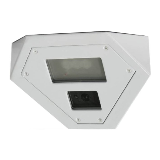
Page 7: Description
DESCRIPTION The EX36N Night Vision Camera has been designed with tilt on its faceplate to allow corner mounting and provide better view angle in small rooms. The housing and faceplate consist of tough materials to withstand damage in hostile environments such as prison cells and psychiatric wards. -
Page 8: Unpacking
Check the parts list and confirm all items have been located. Inspect the equipment thoroughly to ensure nothing was damaged in transit. Contact BOSCH Service Center if a problem is noted, see the rear page of this booklet for contact numbers. -
Page 9: Initial Preparations
After the wiring has been reconnected, it is advisable to check the camera’s operation before installation. GUIDELINES The installation of the EX36N camera is explained in Sections 1 to 6 listed below. It is important that these steps are followed in sequence: 1. -
Page 10: Section 1. Faceplate Removal
1. FACEPLATE REMOVAL The faceplate must be removed prior to the installation process. This is necessary because the mounting holes need to be accessed. The lens may need to have its directional angle changed. Refer to Figure 1-1 on page 5. Step 1.1 - Place the camera housing on a flat surface. - Page 11 FIGURE 1 – 1 Faceplate Removal...
- Page 12 This view shows the interior layout of the EX3xN camera assembly after the faceplate has been removed. Smaller details such as wiring and terminal blocks are omitted for clarity. Refer to the specific module sections for these details. FIGURE 1 – 2 Layout of Modules...
-
Page 13: Section 2. Input Power Connections
2. INPUT POWER CONNECTIONS The camera unit is pre-connected with an electrically isolated power board for 24V ac or 12V dc operation with no wiring change or wiring polarity. See Figure 2-1 and 2-2 for wiring details. Power Power FIGURE 2 - 1 12VDC or 24VAC Electrically Isolated Board, Camera VRB... - Page 14 VRB Power Input LED Power Input FIGURE 2 -2 Board Connections, LED VRB...
-
Page 15: Section 3. Mounting - Camera Housing
3. MOUNTING - CAMERA HOUSING Select a suitable location that is protected from accidental damage, tampering, and environmental conditions exceeding the camera’s specifications. Caution: The selected mounting location should not place the camera in a situation where its environmental specifications could be exceeded. See page 24 Caution: Ensure the selected location is protected from falling objects, accidental contact... - Page 16 expected conditions of vibration and temperature. • Secure all cabling. • Installations on drywall must use #8 screws and #8 drywall nylon plugs or a superior connection. The camera’s mounting holes are located on the left and right side of the housing. Refer to Figure 3-1 on page 11.
- Page 17 FIGURE 3 – 1 Mounting Holes – EX36 Camera Housing...
-
Page 18: Section 4. Camera - Directional Adjustment
4. CAMERA - DIRECTIONAL ADJUSTMENT Both the camera and the LED array can be adjusted for optimum picture quality. The camera lens can be tilted on its axis via two adjustment screws on the mounting bracket. It can also be moved closer or farther away from the viewing window. - Page 19 Loosen both adjustment screws for tilt or horizontal directional alignment. This action may require trial-and-error attempts to obtain perfect picture alignment. FIGURE 4 – 1 Camera Directional Alignment...
-
Page 20: Power Adjustments
5. LED DIRECTIONAL AND POWER ADJUSTMENTS If the LEDs need to be adjusted for beam spread, the Camera/LED Array Assembly does not need to be removed from the housing. The adjustment can be done by hand. The EX3xN can be powered while making adjustments, but make sure the power cable is not pinched or chafed during this procedure. - Page 21 LED ARRAY - POWER ADJUSTMENTS If adjustment is needed, remove the rear cover for access to the LRB. The EX36N needs to be powered-up while making the LED power adjustments. Cover the photocell to turn the LEDs “ON” (850nm LEDs will have a slight red glow).
-
Page 22: Section 6. Camera Re-Assembly
6. CAMERA RE-ASSEMBLY Make sure all wires are properly connected, all holes are sealed against moisture penetration, and all mounting screws are tight. Step 6.1 - Slide the square foam pad over the camera’s lens. Make sure the pad is as close to the faceplate viewing window as possible and the photocell is not covered by the foam... - Page 23 photocell The foam pad is not symmetrical. Make sure the LED is not covered when installing the foam pad. FIGURE 6 – 1 Camera Re - Assembly...
-
Page 24: Section 7. Troubleshooting - Camera
7. TROUBLESHOOTING - CAMERA PROBLEM POSSIBLE LIKELY CAUSE SOLUTION No Video 1. Power Supply: Check input power connections at the Connections…. terminal: * AC input wires to “ ac IN”. * DC input wires to “ dc IN”. * Loose wires. The supply range is: -Voltage 12 –... - Page 25 Connections: directly to the (cont’d.) monitor. Check the video signal. If okay, the problem is with the interconnections. If still no video, contact BOSCH Service Center. See rear page of this manual for contact information. __________ _________________ Poor Picture...
- Page 26 Horizontal Ground Check the coax Scan Lines, Looping on cable shield is not Rolling Up video cable touching ground, e.g. or Down. at couplings. Reversed Check voltage at video or Low voltage input power cable. faded image Must be >10.5V dc or >12Vac for camera section.
-
Page 27: Section 8. Troubleshooting - Leds
8. TROUBLESHOOTING - LEDs PROBLEM POSSIBLE SOLUTION Fuse Blows - Check fuse rating. - Check for shorting between the enclosure and the input power. Don’t know if LEDS are 850nm LEDs will have a “ON” faint red glow when “ON”. 940nm LEDs are covert. - Page 28 PROBLEM POSSIBLE SOLUTION LEDs are not turning - Make sure the photo “OFF” when sufficient sensor is not covered or ambient light is present hidden behind any object. - Adjust the photocell’s variable resistor towards the “OFF” position. The LEDS will stay “ON” or “OFF”...
-
Page 29: Section 9. General Specifications
9. GENERAL SPECIFICATIONS CCD Sensor....1/3’’ – IR Optimized Video Signal Output.... 1 V p-p, 75 Ohm LED Type....High Perf. 850nm / 940nm Operational Range....-50°C to +50°C (-58°F to 122°F) Humidity Range .....Up to 85% (relative) Power Supply..... 12V dc or 24V ac (60Hz), 19W Window .... - Page 30 Note:...
- Page 31 Note:...
- Page 32 Phone: +65 6319 3450 Telephone+1 888-289-0096 Phone: + 31 40 2577 284 Fax: +65 6319 3499 +1 585-223-9180 Fax: +31 40 2577 330 apr.securitysystems@bosch.com Email: security.sales@us.bosch.com emea.securitysystems@bosch.com www.boschsecurity.com www.boschsecurity.us www.boschsecurity.com © Bosch Security Systems, Inc. 2009; Data subject to change without notice.
Need help?
Do you have a question about the EX36N and is the answer not in the manual?
Questions and answers