
Related Manuals for Siemens MJ-XL


Summary of Contents for Siemens MJ-XL
- Page 1 L(TM) MJ-X Voltage Regulator Control Panel Installation and Operations Manual Manual No. 21-115527-010-04 Siemens Power Transmission & Distribution, Inc.
- Page 2 It does not relieve the user of responsibility to use sound prac- tices in application, installation, operation, and maintenance of the equipment pur- chased. Siemens reserves the right to make changes at any time without notice of obligations. Should a conflict arise between the general information contained in this publication and the contents of drawings or supplementary material, or both, the latter shall take precedence.
-
Page 3: Table Of Contents
5 Reading and Interpreting MJ-XL Control Panel Data ......33 1.1 About This Manual......... 1 1.2 Features of the MJ-XL Control Panel.... 1 5.1 Source and Load Definitions ....... 33 1.3 Mounting onto Siemens Regulators..... 2 5.2 P2 (Source-side voltage) Calculation ..33 1.4 Mounting onto Cooper Regulators .... - Page 4 Neutral .........63 F Communications Module Installation ........64 G Menu Structure Quick Reference..65 G.1 Navigating the Menu and Fast-Path Keys . 65 G.2 MJ-XL Menu Structure........ 66 H MJ-XL Firmware Versions....68 Terminal Strip Wiring ......69 J MJ-XL Jumpers and Battery Replacement .......70 J.1 MJ-XL Jumpers ...........
-
Page 5: Introduction
Introduction 1 Introduction L(TM) The MJ-X Control Panel is a member of the Siemens mately equivalent to MJ-X software version Accu/Stat® series of digital controls, designed for use 2.4507. with many regulators and load tap changer models. Features of the MJ-X... -
Page 6: Mounting Onto Siemens Regulators
Support Documentation Communications The MJ-X provides local communications via the front- In addition to this manual, Siemens provides a number of panel data port, and supports remote communications supporting documents that provide details about the use with the MJ-X Communications Module. -
Page 7: Using The Mj-Xl Operator Panel
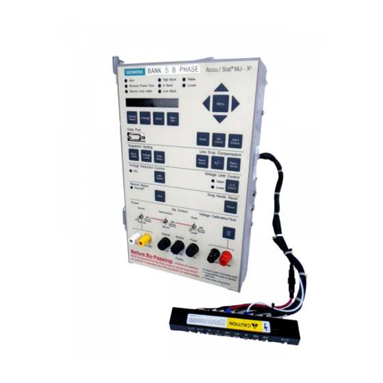
Using the MJ-XL Operator Panel and Controls 2 Using the MJ-X Operator Panel and Controls Accu / Stat MJ - X Indicators Alert High Band Raise Reverse Power Flow In Band Lower Menu Selection Remote Auto Inhibit Low Band 16-Character... -
Page 8: Introduction To The Front Panel
Using the MJ-XL Operator Panel and Controls Introduction to the Front Panel 2.3.1 Menu Selection and Change Keys Use the Menu Selection and Change keys, located in the The Front Panel (Figure 2.1) provides access to all control- top third of the front panel, to view and change controller ler information. - Page 9 Using the MJ-XL Operator Panel and Controls To change an item: Max/Min data items are displayed for a short period of time, after which the display returns to the current value. View the item using either the menu selection keys The length of this period can be selected by the operator.
- Page 10 Using the MJ-XL Operator Panel and Controls Time Delay Key Press this key to view the contents of the <ALERTS> Menu. If any Alerts are active, press this key repeatedly to step through the Alerts in order of priority. If no Alerts are active, the message “No Alerts Active”...
-
Page 11: Indicators
Using the MJ-XL Operator Panel and Controls Reverse Power Flow LED minals. For the MJ-X , pressing the U2/P2 key toggles the test terminal voltage between U2 The Reverse Power Flow (RPF) indicator is illuminated and P2. when the microprocessor senses reverse power flow. The... -
Page 12: Switches
Using the MJ-XL Operator Panel and Controls Raise and Lower LED Indicators the control program is returning the tap position to Neu- tral. The Raise indicator is on whenever the tap changer motor is raising the tap position. The Lower indicator is on when- Band Indicator Status Table 2.2... -
Page 13: Binding Posts
Using the MJ-XL Operator Panel and Controls Binding Posts Tap Control Switches Front panel binding posts are dual banana-style Remote/Auto/Manual Switch (Mode Select receptacles on standard 0.74 inch centers. Switch) This three-position switch determines whether the MJ-X External Source Binding Posts... -
Page 14: Fuses
Using the MJ-XL Operator Panel and Controls Fuses DANGER Power Fuse This 4.0 Amp fuse protects the MJ-X Control Panel circuit Open CT secondary will result in high and the tap changer motor circuit. voltage at CT terminals. Sensing Fuse Will result in death or serious injury including equipment damage. - Page 15 Using the MJ-XL Operator Panel and Controls Power and Motor Control Terminal Contacts A simplified schematic drawing of the power and motor control terminal connections is shown in Figure 2.3 below Power Switch Connections for Connections for External Motor Power...
-
Page 16: Local Data Port
Using the MJ-XL Operator Panel and Controls Local Data Port The Local Data Port on the front panel supports connec- Jumpered for DTE tion to a PC or other communications device. It transfers data in either direction: the MJ-X Control Panel can pro-... -
Page 17: Viewing And Changing Mj-Xl Data Items1
Viewing and Changing MJ-XL Data Items 3 Viewing and Changing MJ-X Data Items The MJ-X Control Panel stores a considerable amount of Setup Menus define the environment. In general, data. Some of the data items are setpoints used to control these Menus are only used at installation. -
Page 18: Changing Data Items
Viewing and Changing MJ-XL Data Items Changing Data Items If you are not sure where you are in the Menu structure, press the Menu key once to return to the top of that To change data, you must first view it, as described above. -
Page 19: Using The Fast-Path Keys To View/Change Data Items
Viewing and Changing MJ-XL Data Items Using the Fast-Path Keys to View/ Changing Alpha or Numeric Settings Change Data Items The process of changing alpha or numeric settings is simi- lar to that of changing configuration parameters, except Fast-path keys are the labeled keys on the middle portion... -
Page 20: Setting Up The Mj-Xl Control Panel
The <CONFIGURE> Menu Table 4.1 DATA ITEM DESCRIPTION VALID INPUTS DEFAULT TapChngr Tap Changer Type SIEMENS, GE, LTC, LTC.5, COOP SD, or COOP DD SIEMENS - - - Type Regulator type STRAIGHT or INVERTED STRAIGHT - - - Syst System wiring configuration... -
Page 21: Setup For Retrofit Panels
M a d e i n U S A J a c k s o n , M S 21-115905-002 Figure 4.1 Typical Siemens Regulator Nameplate for older ANSI Type B (Inverted) Regulator (Regulator type not identified on nameplate) Note: Items are not highlighted on actual nameplate. - Page 22 M a d e i n U S A J a c k s o n , M S 21-115905-002 Figure 4.3 Typical Siemens Regulator Nameplate for ANSI Type B (Inverted) Regulator Note: Items are not highlighted on actual nameplate. Siemens Power Transmission & Distribution, Inc.
- Page 23 Setting Up the MJ-XL Control Panel 4.3.1 TapChngr (Tap Changer Type) 4.3.4 DeltaPwr (Delta Power) The TapChngr data item defines the tap changer mecha- The Delta Pwr item defines the wiring arrangement for nism type. Tap changer mechanisms vary among regulat- Delta-connected systems.
- Page 24 Full Load Current as “XXX Amps.” measurements. Enter the value for the Full Load Current setting into the MJ-XL. See Figures 4.1 to 4.3 for examples. View CTratio: then specify the ratio exactly as specified on the nameplate. See Figures 4.1 to 4.3 for examples.
- Page 25 Setting Up the MJ-XL Control Panel 4.3.17 Time and Date Items The MJ-X Control Panel senses the reversal and modifies its operation based on the Power Flow Mode selected. Time (Time of Day) This section provides an introduction to each of the The Time data item allows you to set the real-time clock.
- Page 26 Setting Up the MJ-XL Control Panel 4.3.21 Screen t.o. (Screen Time Out) To use the Sliding Window method, view Dmd Type and specify WINDOW. Then view DmdTime and specify the The Screen t.o. data item defines the length of time that length of the period in minutes (1 to 999);...
-
Page 27: Setting Control Levels- The
Setting Up the MJ-XL Control Panel Setting Control Levels— Variables in the <REGULATOR> Menu are summarized in Table 4.2 and described in detail in the following sections. the <REGULATOR> Menu The <REGULATOR> Menu defines setpoints used by the MJ-X Control Panel when operating in Automatic Mode.Menu - Page 28 Setting Up the MJ-XL Control Panel 4.4.1 Regulator Setpoints Time Delay Setpoint Regulator setpoints define the operating limits for Auto- The Time Delay setpoint defines the amount of time the matic mode operation. Two sets of limits are maintained: controller will wait before commanding a tap change.
- Page 29 Setting Up the MJ-XL Control Panel VRC Mode MJ-3A Mode (“Pulsed” Input) This data item defines the VRC mode of operation. Select This mode simulates MJ-3A VRC; it uses only one exter- the desired mode, using the VRC Mode data item. Four nal contact(VRC1).
-
Page 30: Activating Data Logging- The
Setting Up the MJ-XL Control Panel · · Activating Data Logging— AutoVRCn% (rated current). the <LOG SETUP> Menu Example 1 The MJ-X Control Panel can record status information AutoVRC1%I = 60%; AutoVRCset1 = 3%. that will help reconstruct past occurrences. Two logs are maintained: an Event Log, and an Interval Log.Menu -
Page 31: Password Security Protection- The
Setting Up the MJ-XL Control Panel Password Security Protection— To activate Events Logging, view Log Event; then select ON. You must also define which events are to be logged. the <PASSWORD> Menu To activate logging for a specific Event, view the appropri- ate Event = data item, and select ON for that Event.Menu - Page 32 Setting Up the MJ-XL Control Panel administrator. This person would be responsible for estab- 4.6.2 The MJ-X <PASSWORD> Menu lishing the password protection scheme and for making The <PASSWORD> Menu serves three purposes: changes to the passwords as necessary; He/she would be the only individual requiring knowledge of the “System...
- Page 33 Setting Up the MJ-XL Control Panel takes place. When password checking is enabled for a 4.6.3 Setting Up the MJ-X Security System given Level, entry of a valid password will be required before you can change/reset any data item that is pro- Entering the System Key tected at that Level.
-
Page 34: Communications Definition- The
Setting Up the MJ-XL Control Panel Communications Definition— passwords can only be changed or reset after you enter the Level 2 password for that Menu. the <COMMUNICATIONS> Menu Entering passwords The <COMMUNICATIONS> Menu provides data items for setting up local communications and remote communi- You can go directly to the <PASSWORD>...Menu - Page 35 Setting Up the MJ-XL Control Panel Note 3, Collecting MJ-X Data with a (Cooper) Data Reader [Using the DRIP].) Communications Module Configuration Items Table 4.9 To set the Communications unit address, view Comm DATA ITEM DESCRIPTION SELECTIONS Addr under the <COMMUNICATIONS> Menu. Enter the desired address.
-
Page 36: Hardware Configuration- The
Number and Product Revision code for the MJ-X Control tion items: Panel. These are set at the factory and cannot be changed. U2 Cal Refer to the MJ-XL Communications Module Instruction P2 Cal Manual for information about the Comm Module items: C/C2low CM Test? C/C2med...Menu -
Page 37: Reading And Interpreting Mj-Xl Control Panel Data
Reading and Interpreting MJ-XL Control Panel Data 5 Reading and Interpreting MJ-X Control Panel Data The MJ-X Control Panel microprocessor maintains a con- “L” bushing voltage is the “Load voltage. With power siderable amount operational information— both flowing in the reverse direction, the “S” bushing voltage is present and historical: the “Load”... - Page 38 Reading and Interpreting MJ-XL Control Panel Data displayed. Pressing the Ù key displays the last metered power flow conditions, load current includes regulator data item. An example for displaying min/max time and excitation current which could be approximately 10% date stamps is shown below: higher or lower than actual load current.
-
Page 39: Demand Data- The
Reading and Interpreting MJ-XL Control Panel Data Freq (Line Frequency) The Freq data item displays the line frequency in Hertz Demand Data Items Table 5.4 (present, max, min). Fdmd Vld Load Voltage demand kWhr F and kWhr R (Forward and Reverse Real...Menus -
Page 40: Interval Log - The
Reading and Interpreting MJ-XL Control Panel Data To access log data, view the <EVENT LOG> Menu with Table 5.6 describes the data that is logged at the conclu- the Menu Selection keys; then use the Ù and Ú keys to sion of each interval.Menu -
Page 41: Operation Counter Data - The
Reading and Interpreting MJ-XL Control Panel Data Operation Counter Data - Dead Reckoning for Siemens Regulators the <COUNTERS> Menu The control program keeps track of the regulator tap posi- tion by means of a “dead reckoning” procedure, analo- Operation counters record the stepping operations of the gous to navigational dead reckoning.Menu -
Page 42: Alerts- The
Reading and Interpreting MJ-XL Control Panel Data Alerts— the <ALERTS> Menu If the Alert name is flashing, acknowledgment is required. Alerts represent exception conditions. An Alert condition 5.8.2 Acknowledging an Alert may be presently active, or it may have been active at To acknowledge the Alert, press the Cancel/Reset key.Menu -
Page 43: Harmonics Data- The
Reading and Interpreting MJ-XL Control Panel Data Harmonics Data— 5.10 Local Data Port— the <HARMONICS> Menu the <COMMUNICATIONS> Menu Harmonics data are calculated for load voltage, source The <COMMUNICATIONS> Menu contains Local Data voltage, and load current. The <HARMONICS> Menu Port status.Menu -
Page 44: Mj-Xl Control Panel Automatic Mode
MJ-XL Control Panel Automatic Mode 6 MJ-X Control Panel Automatic Mode This Chapter covers operating principles of the MJ-X con- can use the Tap Raise/Lower switch (on the MJ-X front trol program and describes the various functions per- panel) to control the tap position directly. Status informa- formed by the microprocessor. -
Page 45: Overview Of Automatic Control Algorithm
MJ-XL Control Panel Automatic Mode Overview of Automatic Control Remote (Communications Algorithm Module) Override of Automatic Control The automatic control algorithm maintains the output volt- age within its prescribed limits while following a control Place the Remote/Auto/Manual switch in the Remote hierarchy. -
Page 46: Voltage Limit Control
It is possible for Reverse Power Flow conditions to occur in regulators with no source-side voltage input (e.g., no “Source-Side PT” for Siemens Inverted Regulators.), In this case, the MJ-X uses the calculated source-side volt- age for performing reverse power flow regulation. See... - Page 47 MJ-XL Control Panel Automatic Mode sections 5.1 and 5.2 for details on source-side voltage cal- During Reverse Operations, “reverse” Meter data is dis- culation. played. The following parameters determine whether the tap change motor is energized to raise the tap position or...
- Page 48 MJ-XL Control Panel Automatic Mode 6.6.3 Power Flow Modes Idle Reverse, and Co-generation. Your selection of one of these determines which algorithm the control program The MJ-X supports six Power Flow Modes: Forward uses under reverse power flow conditions. Locked, Reverse Locked, Bidirectional, Neutral Reverse, Tap Changer Direction Table 6.3...
- Page 49 MJ-XL Control Panel Automatic Mode F LOCK (Forward Locked Mode) R LOCK (Reverse Locked Mode) This mode of operation is intended for use on systems This mode of operation is intended for use on systems where reverse power flow is not anticipated. Tap changes where forward power flow is not anticipated.
- Page 50 MJ-XL Control Panel Automatic Mode BI-DIR (Bi-directional mode) IDLE R (Idle Reverse) This mode of operation is intended for use on systems This mode of operation is intended for use on systems where reverse power flow is anticipated and voltage regu- where reverse power flow is an abnormal situation.
- Page 51 MJ-XL Control Panel Automatic Mode NEUT R (Neutral Reverse) CO-GEN (Co-generation) This mode of operation is intended for use on systems This mode of operation is for use on systems where where reverse power flow is an abnormal situation. power flows from Utility to consumer at certain times and from consumer to Utility at other times.
-
Page 52: Software For Communicating With The Mj-Xl Control Panel
Software for Communicating with the MJ-XL Control Panel 7 Software for Communicating with the MJ-X Control Panel Communications Software Uploading New MJ-X Software Siemens has developed a Windows-based communica- Siemens offers a software application, called MJXtra, for tions software application called MJXplorer. All configura-... -
Page 53: Mj-Xl Control Panel Basic Troubleshooting
Self Test Fault This alert indicates a failure of one or more MJ-X self tests. Consult your Siemens representative for instructions. Note: For more detailed information, request the MJ-X Troubleshooting Guide from your Sie- mens PT &... -
Page 54: Troubleshooting Based On Alert Messages50
To calibrate, press the Change key, then the Ú or Ammeter connected at C/C2.) Ù key to make the value shown at the MJ-XL display agree with the external ammeter value. When the change To check C/C2 Medium calibration, apply a nominal 80 mA is complete, press the Save key. -
Page 55: Mj-Xl Self Testing
A checksum failure indicates a problem with the unit. A MJ-X Self Testing checksum or other self-test failure will activate the “Self Test Fault” alert. If this alert occurs, contact your Siemens After reset, the MJ-X runs through an internal diagnostics Power Transmission & Distribution representative for routine. -
Page 56: A Specifications
45 to 65 Hz High Energy Surge: ANSI/IEEE C62.41-1980 U2 and P2 inputs only Not susceptible to upset due to high radio frequency inter- ference (RFI) defined by the following: RFI Susceptibility: ANSI/IEEE C37.90.2-1987. Siemens Power Transmission & Distribution, Inc. -
Page 57: B Physical Installation On Siemens Regulators
Appendix B: Physical Installation on Siemens Regulators B Physical Installation on Siemens Regulators Physical installation consists of placing the MJ-X Control Note 2: The control being replaced may incorporate a Panel in its weatherproof housing and connecting the jumper between the P2 and U2 terminals on the female Polarized Disconnect Switch to the regulator. - Page 58 It is WARNING strongly recommended that MJ-X controller repair, test- ing, and calibration be performed only by Siemens autho- rized repair facilities. Hazardous voltage will be present on various control leads when regulator is energized.
-
Page 59: C Regulator Control Diagrams
Appendix C: Regulator Control Diagrams C Regulator Control Diagrams Typical Control Diagrams - For Reference Only ANSI Type ‘ A’ (Straight) Regulator Control Diagram Figure C.1 Siemens Power Transmission & Distribution, Inc. - Page 60 Appendix C Regulator Control Diagrams ANSI Type ‘ B’ (Inverted) Regulator Control Diagram Figure C.2 Siemens Power Transmission & Distribution, Inc.
-
Page 61: D Menu Parameters
Reactance Setting = 6.67 x 3 x 0.692 = 14V Using knowledge of the distribution feeder and the tables below, establish the conductor resistance and reactance per mile of feeder. EXAMPLE: Conductor 4/0 ACSR, Regular Flat Spacing at 24 inches. Siemens Power Transmission & Distribution, Inc. - Page 62 You may also download this application from enter the system values and the application automatically the Siemens web site. Go to www.siemenstd.com, select calculates the resistive and reactive components for you. Products, and then the Voltage Regulator item. This Enter these values in the MJ-X <REGULATOR>...
-
Page 63: Configure> Menu: Transformer Polarity
(ANSI type A) without forced air cooling the Regulator nameplate. The Utility transformer polarity for Single-Phase Straight Design regulators can be determined from the regulator nameplate schematic diagram. The Utility winding taps are labeled Un -- Ux, E2. Siemens Power Transmission & Distribution, Inc. - Page 64 14400 P3 - 120 13200 P4 - 120 7200 P5 - 120 From the table, the system load voltage is 7200 volts; therefore, U2 would be connected to U6. Now check the connection diagram: Siemens Power Transmission & Distribution, Inc.
- Page 65 U6 to the Right of E2 Figure D.4 left of E2, then UtilityPol:NORM (see Figure D.6). • If U2 is connected to a “U” terminal which is to the right of E2, then UtilityPol:REV (see Figure D.7). Siemens Power Transmission & Distribution, Inc.
- Page 66 U2 Connects to a “U” Terminal (U7 or U8) Which is to the Left of E2 Figure D.6 A phase B phase C phase U2 Connects to a “U” Terminal (U7 or U8) Which is to the Right of E2 Figure D.7 Siemens Power Transmission & Distribution, Inc.
-
Page 67: E Hazards Of Bypassing A Regulator Off Neutral
The circuit is activated when the regulator is in the neutral position. A test switch on the MJ-X Control Panel can be used to verify proper operation of the Neutralite. Siemens Power Transmission & Distribution, Inc. -
Page 68: F Communications Module Installation
• RS-232/485 Communications Module, shown in Fig- ure F.2. Refer to the MJ-X Communications Module Installation Manual (Siemens Manual # 2-115527-017 for complete information on installing and testing the Communications Module. RS-232/485 Communications Module Figure F.2 MJ-XL Fiber Optic Communications Module Figure F.1... -
Page 69: G Menu Structure Quick Reference
Circuit Protection Fuses at the PDS. Press again to view the P2 voltage at the PDS. Use this key for calibrating the panel. See Section 8.4 for details. Navigating the Menu and Fast-Path Keys Figure G.1 Siemens Power Transmission & Distribution, Inc. -
Page 70: Mj-Xl Menu Structure
MJ-3A VRC% Min/Max t.o. Screen t.o. AutoVRCset1 Function t.o. AutoVRCset2 Basis Volts AutoVRC1 %I R Limit AutoVRC2 %I L Limit TapAlert VLC Enable TapPosHold VLC Select VLC Upper Version VLC Lower Memo 1 Memo 2 Siemens Power Transmission & Distribution,Inc. - Page 71 Tapmin Total Ops *Interval log data includes instantaneous, maximum, mini- mum, and demand values for this item. **Viewing Log Tip: While viewing “ID” (1 ) screen, press Left/Right Arrows to view previous “IDI screen. Siemens Power Transmission & Distribution, Inc.
-
Page 72: H Mj-Xl Firmware Versions
Appendix H: MJ-XL Firmware Versions MJ-X Firmware Versions This version of the MJ-X Installation and Operation Man- ual describes the initial version of the MJ-X firmware, Version 3.01. The features in this version are the same as those for the previous MJ-X Version 2.4507 firmware. -
Page 73: I Terminal Strip Wiring
Appendix I Terminal Strip Wiring I Terminal Strip Wiring Siemens Power Transmission & Distribution, Inc. -
Page 74: J Mj-Xl Jumpers And Battery Replacement
Appendix J MJ-XL Jumpers and Battery Replacement J MJ-X Jumpers and Battery Replacement MJ-X Jumpers The locations of the MJ-X jumpers and battery are shown in the drawing below. The table on the next page describes the jumpers and the default settings. -
Page 75: Battery Replacement
Appendix J MJ-XL Jumpers and Battery Replacement MJ-X Jumper Descriptions and Default Connections Table J.1 Jumper Default Shunt Description Location This jumper shorts signals C&C2 (P3B-11&12). J1 is a redundant jumper, since MJ-X ships from the factory with a terminal strip jumper across P3B-11&12. With either jumper installed, the terminal strip, the CT current path for the regulator is complete. -
Page 76: K Terminal Strip Connections
Output drag hands of the Tap Position Dial mounted on the regulator. Bold indicates standard "Polarized Disconnect Switch (PDS)" signals. For Siemens regulators, these ten signals connect to the corresponding pins of the PDS connector block. Siemens Power Transmission & Distribution, Inc. - Page 77 Remote position. It is normally jumpered to U at the terminal block, but it can be connected to an external AC source. [Alternatively, an external relay con- tact can be placed between the U and U6 contacts for external control of the MJ-XL manual and remote operations.] This is the signal from U2, after the power switch (assuming the switch is in the "Nor-...
- Page 78 Normally-closed contact of Auxiliary Output Relay. (See P3A-3.) Relay Output 3 & 4 INHIB IN+ INHIB IN directly disables the MJ-XL motor control relays. Through the microproces- Contact closure & INHIB IN- sor, this signal asserts Automatic Inhibit of motor Raise/Lower operations, and acti- (Input) vates the Auto Inhibit Indicator.
-
Page 79: L Mj-Xl Operating Procedures
Operating Procedures View/Set Time Delay Value Use the following instructions as a quick reference for per- Press Time Delay Fast-Path key forming many of the standard MJ-XL operating proce- dures. Read time delay on display View Instantaneous Load Voltage (Vld) - Page 80 Position Indicator value 13. Press Right Arrow to step to the next digit to be Press Save key to save new value changed 14. Press Save key to save the new date Siemens Power Transmission & Distribution, Inc.
- Page 81 Compensation Multipliers 59 Resistance 6 Configuration 16 Time Delay 6 CONFIGURE Menu 16–22, 57, 59 Voltage Level 5 Configure the MJ-XL Control Panel 76 Voltage Limit Control 6 Connections 69 Voltage Reduction Control 6 Connections, Terminal Strip 72 Field Maintenance 54...
- Page 82 Idle Reverse 21, 46 Logging Requirements 16 Neutral Reverse 21, 47 Low Current Threshold 20 Reverse Locked 45 LTCs 2 Reversed Locked 21 Tap Changer Direction 44 Power Fuse 10 Main Processor Board Version 32 Siemens Power Transmission & Distribution, Inc.
- Page 83 View/Set Forward Voltage Level Value 75 Scroll Keys 4, 13 View/Set Line Drop Compensation Values 75 Security Definition 16 View/Set the MJ-XL Clock (Time and Date 76 Self Test 51 View/Set Time Delay Value 75 Sensing Fuse 10 Viewing Alerts 38...
- Page 84 Index VRC Mode 25 LOCAL 25 OFF 25 REMOTE 25 VRC Status 24, 39 VRC1 In 24 VRC2 In 24 Website 2 Siemens Power Transmission & Distribution, Inc.
- Page 86 Siemens Power Transmission & Distribution Inc. P.O. Box 6289 Jackson, MS 39288 21-115527-010-04 Manual No. © 2000 Siemens Power Transmission & Distribution Inc.. 1M 0200TD Printed in U.S.A. SIEMENS is a registered trademark of Siemens AG.