Do you have a question about the HYD3000-ES and is the answer not in the manual?
Questions and answers
Janet Boucher
February 26, 2025
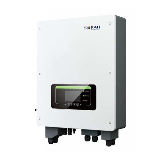
the red alarm shows sometimes what does this mean
1 comments:
Mr. Anderson
February 26, 2025
The red alarm on the Sofar HYD3000-ES indicates a fault or error condition. Possible causes include battery overvoltage (ID05), grid LVRT fault (ID07), PV voltage too high (ID08), internal faults (ID09-ID26, ID53-ID55), insulation resistance too low (ID56), or overheating issues (ID57-ID59). The appropriate action depends on the specific fault code displayed.


Need help?
Do you have a question about the HYD3000-ES and is the answer not in the manual?
Questions and answers
the red alarm shows sometimes what does this mean
The red alarm on the Sofar HYD3000-ES indicates a fault or error condition. Possible causes include battery overvoltage (ID05), grid LVRT fault (ID07), PV voltage too high (ID08), internal faults (ID09-ID26, ID53-ID55), insulation resistance too low (ID56), or overheating issues (ID57-ID59). The appropriate action depends on the specific fault code displayed.
This answer is automatically generated