Sofar HYD 6000-EP User Manual
Hide thumbs
Also See for HYD 6000-EP:
- Installation and operating manual (107 pages) ,
- User manual (104 pages) ,
- User manual (85 pages)
Table of Contents
Advertisement
Advertisement
Table of Contents

Subscribe to Our Youtube Channel
Related Manuals for Sofar HYD 6000-EP


Summary of Contents for Sofar HYD 6000-EP
- Page 1 User manual HYD 3000 ... 6000-EP Copyright © Shenzhen SOFAR SOLAR Co., Ltd.
-
Page 2: Table Of Contents
6.1. Double Check................- 36 - 6.2. First Time Setup (IMPORTANT!)........- 36 - 6.3. Menu..................- 40 - 7. Troubleshooting................- 53 - 8. Technical Data.................. - 60 - 9. Quality Assurance................- 66 - Copyright © Shenzhen SOFAR SOLAR Co., Ltd. - Page 3 SOFARSOLAR reserves the right of final interpretation.This manual is subject to change according to user’s or customer’s feedback.Please check our website at http://www.sofarsolar.com for latest version. Document Updates V2.1 2023-11-10 Copyright © Shenzhen SOFAR SOLAR Co., Ltd.
-
Page 4: Preface
HYD 3K~6K-EP inverters: HYD 3000-EP HYD 3680-EP HYD 4000-EP HYD 4600-EP HYD 5000-EP HYD 5500-EP HYD 6000-EP Keep this manual where it will be accessible at all times. Target Group This manual is intended for qualified electrical technical personnel who are responsible for inverter installation and commissioning in the PV power system and PV plant operator. - Page 5 Caution Attention indicates potential risks which, if not avoided, may lead to equipment fault or property damage. Attention Note provides tips that are valuable for the optimal operation of the product. Note Copyright © Shenzhen SOFAR SOLAR Co., Ltd.
-
Page 6: Basic Safety Information
User manual HYD 3000 ... 6000-EP 1. Basic safety information 1.1. Safety instructions Read and understand the instructions of this manual, and be familiar with relevant safety symbols in this chapter, then start to install and troubleshoot the equipment. According to the national and state requirements, before connecting to the electrical grid, you must get permission from the local electrical grid operation can only be performed by qualified electrical engineer. - Page 7 User manual HYD 3000 ... 6000-EP an appropriate objects with enough load bearing capacity (such as walls, PV racks etc.), and ensure that inverter is vertical placed. Choose a place suitable for installing electrical devices. And assure there is enough fire exit space, convenient for maintenance.
- Page 8 User manual HYD 3000 ... 6000-EP All installation accomplished only by professional electrical engineer! Must be trained; Completely read the manual operation and understand Warning relevant matter. Get permission from the local electrical gird operator, complete all electrical connections by professional electrical engineer, then connect inverter to electrical grid.
-
Page 9: Symbols And Signs
User manual HYD 3000 ... 6000-EP to electromagnetic noise of external system.Noise emission level: influence of electromagnetic emission upon environment. Electromagnetic radiation from inverter may be harmful to health! Please do not continue to stay around the inverter in less than 20 Danger cm when inverter is working. - Page 10 User manual HYD 3000 ... 6000-EP HYD 3K~6K-EP Please read this manual before install This indicates the degree of protection of the equipment according to IEC standard 70-1 (EN 60529 June 1997). Positive pole and negative pole of the input voltage (DC). This side up, HYD 3K~6K-EP inverter must always be transported, handled and stored in such a way that the arrows always point upwards.
-
Page 11: Product Characteristics
User manual HYD 3000 ... 6000-EP 2. Product characteristics 2.1. Product informations HYD 3K~6K-EP inverter is a single-phase photovoltaic energy storage inverter integrating grid-connected photovoltaic inverter and battery energy storage. The HYD 3K~6K-EP inverter has a variety of built-in operating modes to suit the diverse user needs. -
Page 12: Size Description
User manual HYD 3000 ... 6000-EP 2.2. Size description Fig. 2-2 Size chart Front view left view Bracket ① ② ③ 2.3. Function characteristics The HYD 3K~6K-EP energy storage inverters allow up to 10% overloading to maximize power output, and the Uninterruptible Power Supply (UPS) mode can support inductive loads such as air conditioners or refrigerators with an automatic switchover time of less than 10 milliseconds. - Page 13 User manual HYD 3000 ... 6000-EP - 8 - Copyright © Shenzhen SOFARSOLAR Co., Ltd。...
-
Page 14: Installation
User manual HYD 3000 ... 6000-EP 3. Installation Installation notes Do NOT install the HYD 3K~6K-EP on flammable material. Do NOT install the HYD 3K~6K-EP in an area used to store Flammable or explosive material. Danger The enclosure and heat sink are very hot while the inverter is working, therefore do NOT install the HYD 3K~6K-EP in places where you might touch them inadvertently. - Page 15 User manual HYD 3000 ... 6000-EP Rear panel 1pcs PV+ input terminal 2pcs PV- input terminal 2pcs Metal terminals secured to PV+ input power 2pcs cables Metal terminals secured to PV- input power 2pcs cables BAT- input terminal 1pcs BAT+input terminal 1pcs M6 Hexagon screws 3pcs...
-
Page 16: Product Overview
User manual HYD 3000 ... 6000-EP Split Core Current 1pcs Transformer COM 16pin connector 1pcs Communication cable 1pcs DDSU666 Single-phase electronic type guide 1pcs(optional) rail mounting electric energy meter Manual 1pcs The warranty card 1pcs Quality Certificate 1pcs 3.2. Product Overview HYD 3K~6K-EP inverter is 100% strictly inspected before package and delivery. -
Page 17: Tools
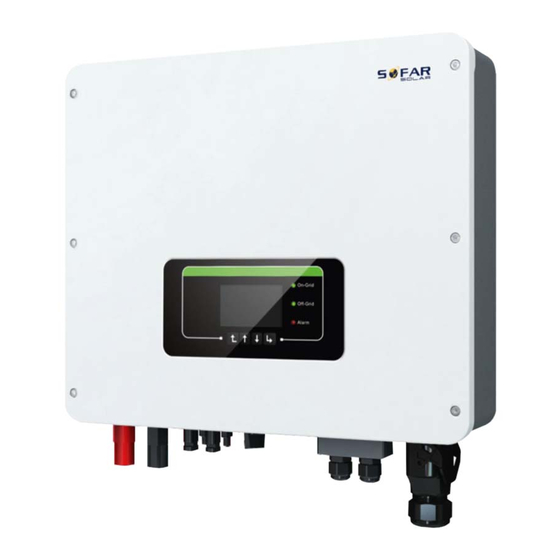
User manual HYD 3000 ... 6000-EP Table 3-2 HYD 3K~6K-EP inverter overview Battery input terminals Link Port 1 DC switch PV input terminals Grid connection port USB/WiFi Load connection port Link Port 0 3.3. Tools Prepare tools required for installation and electrical connections. Table 3-3 Tools required for installation and electrical connections. -
Page 18: Installation Environment
User manual HYD 3000 ... 6000-EP Crimping tool Used to crimp power cables Multi-meter Used to check grounding With an open end of larger than or greater Used to tighten expansion bolts than 32 mm Marker Used to mark signs Measuring tape Used to measure distances Used to ensure that the rear panel is... -
Page 19: Moving The Hyd 3K~6K-Ep
User manual HYD 3000 ... 6000-EP Comply with the following requirements when determining the installation position. Fig. 3-3 Installation Position of HYD 3K~6K-EP inverter ① ② ③ ④ ⑤ ⑥ ⑦ 3.6. Moving the HYD 3K~6K-EP Step 1 Open the packaging, insert hands into the slots on both sides of the inverter and hold the handles, as shown in Fig.3-4. -
Page 20: Installing Hyd 3K~6K-Ep
User manual HYD 3000 ... 6000-EP ① ② Step 2 Lift the inverter from the packing case and move it to the installation position. To prevent device damage and personal injury, keep balance when moving the inverter because the inverter is heavy. Do not put the inverter with its wiring terminals contacting the floor because the power ports and signal ports are not designed to support the weight of the inverter. - Page 21 User manual HYD 3000 ... 6000-EP ① ② ③ ④ ⑤ - 16 - Copyright © Shenzhen SOFARSOLAR Co., Ltd。...
-
Page 22: Electrical Connections
Table 4-1 Relevant current parameters of each model IscPV(absolute Maximum output over current Model maximum) protection HYD 3000-EP HYD 3680-EP HYD 4000-EP HYD 4600-EP 18A/18A 20.9A HYD 5000-EP 21.7A HYD 5500-EP HYD 6000-EP 27.3A - 17 - Copyright © Shenzhen SOFARSOLAR Co., Ltd。... -
Page 23: Wire Instructions
User manual HYD 3000 ... 6000-EP NOTE:The DVC is the voltage of a circuit which occurs continuously between any two live part in the worst-case rated operating condition when used as intended. Table 4-2 The decisive voltage class(DVC) Interface PV input port DVCC Grid connection port DVCC... -
Page 24: Connecting Pgnd Cables
User manual HYD 3000 ... 6000-EP 4.2. Connecting PGND Cables Connect the inverter to the grounding electrode using protection ground (PGND) cables for grounding purpose. The inverter is transformer-less, requires the positive pole and negative pole of the PV array are NOT grounded. Otherwise it will cause inverter failure. -
Page 25: Pv Connection
User manual HYD 3000 ... 6000-EP 1.Screw 2.OT Terminal 3.Tapped hole ③ 4.3. PV Connection Procedure: Step 1 Select the appropriate cable type and specifications according to the table4-3.Remove cable glands from the positive and negative connectors.( It is recommended that the positive and negative be distinguished by different colors). Step 2 Remove the insulation layer with an appropriate length from the positive and negative power cables by using a wire stripper as show in Fig. -
Page 26: Battery Connection
User manual HYD 3000 ... 6000-EP Insert the positive and negative connectors into corresponding PV terminals of the inverter until you hear a "click" sound, as shown in Fig. ⑥ To remove the positive and negative connectors from the inverter, insert a removal wrench into the bayonet and press the wrench with an appropriate strength, as shown in Fig. -
Page 27: Load Connection
User manual HYD 3000 ... 6000-EP ② ③ ① ⑥ ⑤ ④ 4.5. Load connection Procedure: Step 1 Select appropriate cables according to Table4-3, Remove the insulation layer of the load output cable using a wire stripper according to the figure shown below: A:15~25mm B:6~8mm . - Page 28 User manual HYD 3000 ... 6000-EP Connect the brown wire to the hole labeled "L", fasten the wire using an Cross screwdriver; Connect the blue wire to the hole labeled "N", fasten the wire using an Cross screwdriver. Step 4 Insert the load connector and hear "click", then tighten the waterproof nut at the instantaneous value, as shown in the figure below, to ensure that the cable is firmly connected.
-
Page 29: Grid Connection
User manual HYD 3000 ... 6000-EP ⑥ ⑤ Hold the button to unlock ⑦ 4.6. Grid connection The inverter is equipped with an integrated residual current monitoring unit. When the inverter detects that the residual current exceeds 300mA, the connection to the power grid will be quickly disconnected. - Page 30 User manual HYD 3000 ... 6000-EP If you need to remove the terminals from the machine, use the tool to press on the direction indicated by the big arrow and pull the terminals out. Need to dismantle the end connection, to use the tool, as shown in figure attending ⑩⑪...
-
Page 31: External Communication Interface
User manual HYD 3000 ... 6000-EP 4.7. External communication interface 4.7.1 USB/WIFI communication interface Fig.4-6 USB/WIFI communication interface ② ③ ① Table 4-4 Interface description Definition Function Note GND.S USB power - The USB power supply is USB data + 5V/1A;... - Page 32 User manual HYD 3000 ... 6000-EP The operation information (generated energy, alert, operation status) of the inverter can be transferred to PC or uploaded to the server via WiFi/GPRS Users can choose to use web or APP for monitoring and viewing according to their needs. They need to register an account and bind the device with the WiFi/GPRS SN number.
- Page 33 User manual HYD 3000 ... 6000-EP ① ② ③ ④ ⑤ 1. RS485( Wired monitoring or inverter cascade monitoring ) Refer to the figure shown below, connect the RS485+ and RS485- of the inverter to the TX+ and TX- of the RS485→ USB adapter, and connect the USB port of the adapter to the computer.(NOTE :...
- Page 34 User manual HYD 3000 ... 6000-EP multiple inverters are connected via RS485 wires, set communication address to differentiate inverters , please refer this manual<6.3.1System setting→8.Communication Addr>) Fig.4-11 RS485 connection(cascade of monitoring between inverters) 2. Logic interface The logic interface pin definitions and circuit connections are as follows: Logic interface pin are defined according to different standard requirements (a)...
- Page 35 User manual HYD 3000 ... 6000-EP Pin NO. Pin name Description Connected to (RRCR) Relay contact 1 input K1 - Relay 1 output Relay contact 2 input K2 - Relay 2 output Relay contact 3 input K3 - Relay 3 output Relay contact 4 input K4 - Relay 4 output Relays common node...
- Page 36 User manual HYD 3000 ... 6000-EP NOTE:The direction of the current transformer is shown in fig. ④. Fig.4-14 Meter ① ② ③ ④ If you need to use the CT alone, attach the CT to PIN13 and PIN14. There are two ways to get grid current information : Plan A:CT Plan B:Meter +CT - 31 -...
- Page 37 User manual HYD 3000 ... 6000-EP Fig. 4-15 Electrical connections (Plan A:CT) - 32 - Copyright © Shenzhen SOFARSOLAR Co., Ltd。...
- Page 38 User manual HYD 3000 ... 6000-EP Fig. 4-16 Electrical connections (Plan B:Meter +CT ) - 33 - Copyright © Shenzhen SOFARSOLAR Co., Ltd。...
- Page 39 User manual HYD 3000 ... 6000-EP 4.7.3 Link Port 0&1-Cascade communication interface Fig.4-17 Link Port ① ② ③ When using the parallel system, the inverter settings and notes please refer to this manual<6.3.2 Advanced setting→6.Parallel setting>. Note(AC LOAD is also parallel for parallel machines): The first and last inverters need to be connected with 8Pin connection terminals.
-
Page 40: Buttons And Indicator Lights
User manual HYD 3000 ... 6000-EP 5. Buttons and indicator lights Fig.5-1 Buttons and indicator lights 5.1. Buttons press “Back” to the previous screen or enter the main interface. press “Up” to the upper menu option or value plus 1. ... -
Page 41: Operation
User manual HYD 3000 ... 6000-EP 6. Operation 6.1. Double Check Please double check the following before operation. Inverter is firmly fastened to the mounting bracket on the wall. PV+/PV- wires are firmly connected, polarity and voltage are correct. BAT+/BAT- wires are firmly connected, polarity and voltage are correct. DC isolator is correctly connected between battery &... - Page 42 User manual HYD 3000 ... 6000-EP Table 6- 1 Set the parameters Parameter Note 1.OSD Language Option The default English. If you are connected to the host computer such 2.System time setting as collector or mobile phone APP, the time and confirmation should have been calibrated to the local time.
- Page 43 User manual HYD 3000 ... 6000-EP Spain NTS Brazil- LV Spain Brazil-230 UNE217002+RD647 Spain island Brazil-254 Turkey Slovakia SK-VSD Denmark Slovakia SK-SSE Denmark DK-TR322 Slovakia SK-ZSD Greece Czechia GR-Cont. Greece GR-Island Ukraine Netherland Norway-LV Belgium Mexico-LV Wide-Range-60H UK-G99 UK-G98 Ireland Thailand China-B Thai-PEA...
- Page 44 User manual HYD 3000 ... 6000-EP France Saudi Arabia FRArrete23 Latvia France VFR 2019 Poland Romania Austria Switzerland Type A Switzerland Type B CAUTION It’s very important to make sure that you have selected the correct country code according to requirements of local authority. Please consult qualified electrical engineer or personnel from electrical safety authorities about this.
-
Page 45: Menu
User manual HYD 3000 ... 6000-EP 6.3. Menu Fig 6-1. Main interface In the main interface, press “Down” button to enter grid/battery parameters page. Main interface Down↓ Grid Output Information Grid(V) ......***.*V AC Current ....**.**A Frequency....**.**Hz Battery Information (1) Batt (V).......****.*V Batt Chrs Curr....**.**A Batt DisChrs Curr..**.**A... - Page 46 User manual HYD 3000 ... 6000-EP 2.Advanced Settings 3.Energy Statistic 4.System Information 5.Event List 6.Software Update 6.3.1 System setting 1. System Setting 1.Language Settings 2.Time 3.Safety Param. 4.Energy Storage Mode 5.Auto Test(Only for Italy) 6.PV Input Mode 7.EPS Mode 8.Communication Addr. 1.
- Page 47 User manual HYD 3000 ... 6000-EP 4.Passive Mode Self-use Mode In Self-use mode, inverter will automatically charge & discharge the battery. generation LOAD generation > LOAD consumption (ΔP < 100W) inverter consumption, the surplus power will won’t charge or discharge the battery. be stored in the battery.
- Page 48 DisCharge End 16 h 00m DisCharge Power 02500 W Passive Mode For more detailed information, please ask representative of SOFAR to get a copy of passive mode communication protocol. 5. Auto Test (ONLY for Italian Market) 5.Auto Test 1.Autotest Fast 2.Autotest STD...
- Page 49 User manual HYD 3000 ... 6000-EP 1. Autotest Fast Start Autotest Press “Ok” to start Testing 59.S1... ↓ Wait Test 59.S1 OK! ↓ Wait Testing 59.S2... ↓ Wait Test 59.S2 OK! ↓ Wait Testing 27.S1... ↓ Wait Test 27.S1 OK! ↓...
- Page 50 User manual HYD 3000 ... 6000-EP ↓ Press “Down” 27.S1: 228V 1508ms ↓ Press “Down” 27.S2 threshold 34.5V 200ms ↓ Press “Down” 27.S2: 227V 205ms ↓ Press “Down” 81>.S1 threshold 50.5Hz 100ms ↓ Press “Down” 81>.S1 49.9Hz 103ms ↓ Press “Down” 81>.S2 threshold 51.5Hz 100ms ↓...
- Page 51 User manual HYD 3000 ... 6000-EP If PV generation < LOAD consumption If PV generation is normal,but LOAD (ΔP > 100W), inverter will discharge consumption=0, the surplus power will be stored in the battery. battery. 8. Communication Addr 8.Communication Addr 1.Communication Addr 2.Baud Rate 6.3.2 Advanced setting...
- Page 52 User manual HYD 3000 ... 6000-EP 2.PYLON-AH 5.Discharge Depth (Only for PYLON) 3.Max Charge (A) 6.Save Depth of Discharge For example: if Discharge Depth = 50% & EPS Discharge Depth = 80%. While grid is connected: Inverter won’t discharge the battery when its SOC is less than 50%.
- Page 53 User manual HYD 3000 ... 6000-EP 4.Logic Interface Enable Disable Factory Reset 1.Clear Energy Data 5.Factory Reset 2.Clear Events Clean the inverter of the total power generation. Cancel 1.Clear Energy Data Please confirm! Clear Clean up the historical events recorded in the inverter. Cancel 2..Clear Events Please confirm!
- Page 54 User manual HYD 3000 ... 6000-EP 6.3.3 Energy Statistic 3.Energy Statistic Today PV ......***KWH Load ......***KWH Export ......***KWH Import.......***KWH Charge.......***KWH Discharge....***KWH Down↓ Month PV ......***KWH Load ......***KWH Export ......***KWH Import.......***KWH Charge.......***KWH Discharge....***KWH Down↓ Year PV ......***KWH Load ......***KWH Export ......***KWH Import.......***KWH Charge.......***KWH Discharge....***KWH...
- Page 55 User manual HYD 3000 ... 6000-EP Hardware Version Power Level Safety Firmware Version Down↓ Inverter Info (2) Software Version Country Down↓ Inverter Info (3) PV Input Mode Energy Storage Mode RS485 Address EPS Mode Down↓ Inverter Info (4) IV Curve Scan Logic Interface Inverter Info (5) Down↓...
- Page 56 HYD-EP_ARM.bin, HYD-EP_DSPM.bin, HYD-EP_DSPS.bin. Step 1 Insert the usb flash drive into the compute. Step 2 SOFAR SOLAR will send the Software code to the user who needs to update. After user receive the file,please decompressing file and cover the original file in usb flash drive.
- Page 57 User manual HYD 3000 ... 6000-EP Start Update Updating DSP1 Updating DSP2 Updating ARM Step 7 If the following errors occur, please upgrade again.If this continues many times, contact technical support for help. USB Fault MDSP File Error SDSP File Error ARM File Error Update DSP1 Fail Update DSP2 Fail...
-
Page 58: Troubleshooting
User manual HYD 3000 ... 6000-EP 7. Troubleshooting This section contains information and procedures for solving possible problems with the inverter. This section help users to identify the inverter fault. Please read the following procedures carefully: Check the warning, fault messages or fault codes shown on the inverter screen, ... - Page 59 User manual HYD 3000 ... 6000-EP Table 7-1 Eventlist Code Name Description Solution The grid voltage is too If the alarm occurs occasionally, the ID001 GridOVP high possible cause is that the electric grid is abnormal occasionally. Inverter will The grid voltage is too ID002 GridUVP automatically return to normal operating...
- Page 60 User manual HYD 3000 ... 6000-EP ConsistentFault_ Leakage current ID029 GFCI consistency error ConsistentFault_ Grid voltage ID030 Vgrid consistency error SpiCommFault(D communication ID033 error (DC) SpiCommFault(A communication ID034 error (AC) ID035 SChip_Fault Chip error (DC) ID036 MChip_Fault Chip error (AC) HwAuxPowerFau Auxiliary power error ID037...
- Page 61 User manual HYD 3000 ... 6000-EP unbalanced If no, please contact technical support. Busbar undervoltage ID067 BusUVP during grid-connection ID068 BusZVP Bus voltage low PV over-voltage Check whether the PV series voltage (Voc) is higher than the maximum input voltage of the inverter.
- Page 62 User manual HYD 3000 ... 6000-EP too high. there is no direct sunlight. Please ensure that the inverter is installed in a cool/well ventilated place. Ensure the inverter is installed vertically and the ambient temperature is below the inverter temperature limit. AC frequency is too Please make sure the grid frequency and ID114...
- Page 63 User manual HYD 3000 ... 6000-EP Fault EEPROM error inverter. Check whether the problem is solved. Communication board ID150 FlashFault If no, please contact technical support. FLASH error SciCommLose(D communication ID153 error (DC) SciCommLose(A communication ID154 error (AC) SciCommLose(F communication ID155 use) error (Fuse)
- Page 64 User manual HYD 3000 ... 6000-EP brush. Do NOT clean the inverter with water, corrosive chemicals, detergent, etc. Heat sink cleaning For the long-term proper operation of inverters, ensure there is enough space around the heat sink for ventilation, check the heat sink for blockage (dust, snow, etc.) and clean them if they exist.
-
Page 65: Technical Data
User manual HYD 3000 ... 6000-EP 8. Technical Data The following parameters may change without notice , please refer to the user manual and DataSheet on our Note website. Battery Parameters Data- 3000-EP 3680-EP 4000-EP 4600-EP 5000-EP 5500-EP 6000-EP sheet Lithium-ion&... - Page 66 User manual HYD 3000 ... 6000-EP PV Input Data- 3000-EP 3680-EP 4000-EP 4600-EP 5000-EP 5500-EP 6000-EP sheet Recommen ded Max.PV 4500Wp 5400Wp 6000Wp 6900Wp 7500Wp 7500Wp 9000Wp input power(Wp) Max.input 600Vd. c. voltage Rated input 360Vd. c. voltage Start-up 100Vd. c. voltage MPPT voltage...
- Page 67 User manual HYD 3000 ... 6000-EP AC Input(Grid) Data- 3000-EP 3680-EP 4000-EP 4600-EP 5000-EP 5500-EP 6000-EP sheet Rated Input L+N+PE,230 Va. c. Voltage Rated Input 50/60 Hz Frequency Max.Input 29.3A 33.4A 35.9 A 41.7 A 43.5 A 43.5A 43.5 A Current AC Output (Grid) Data-...
- Page 68 User manual HYD 3000 ... 6000-EP <3% THDi AC Output Data (Backup) Data- 3000-EP 3680-EP 4000-EP 4600-EP 5000-EP 5500-EP 6000-EP sheet Rated 3000W 3680W 4000W 4600W 5000W 5000W 5000W Output Power Rated Output 13.0 A 16.0 A 17.4 A 20.0A 21.7A 21.7A 21.7A...
- Page 69 User manual HYD 3000 ... 6000-EP Efficiency And Protection Data- 3000-E 3680-E 4000-E 4600-E 5000-E 5500-E 6000-E sheet 99. 9% Max.MPPT Efficiency European 97. 2% 97. 2% 97. 2% 97. 3% 97. 3% 97. 3% 97. 5% Efficiency 97. 6% 97.
- Page 70 User manual HYD 3000 ... 6000-EP General Data 3000-E 3680-E 6000- Datasheet 4000-EP 4600-EP 5000-EP 5500-EP Dimensions 482*503*183 mm (W*H*D) 21. 5kg Weight Non-Isolation Inverter Topology Class I Protective Class Standby <10W Self-consumption Operating -30℃ to +60℃ (derating above +45℃) Temperature Range Relative Humidity...
-
Page 71: Quality Assurance
User manual HYD 3000 ... 6000-EP 9. Quality Assurance Standard warranty period The standard warranty period of inverter is 60 months (5 years). There are two calculation methods for the warranty period: 1. Purchase invoice provided by the customer: the first flight provides a standard warranty period of 60 months (5 years) from the invoice date;... - Page 72 User manual HYD 3000 ... 6000-EP Without the consent of our company to change equipment or replace parts; Use unqualified materials to support our company's products, resulting in product failure; Technicians of non-company modify or attempt to repair and erase the product serial number or silk screen;...
- Page 73 Version 2.1 User manual HYD 3000 ... 6000-EP - 68 - Copyright © Shenzhen SOFARSOLAR Co., Ltd。...
Need help?
Do you have a question about the HYD 6000-EP and is the answer not in the manual?
Questions and answers