Advertisement
Quick Links
Advertisement

Related Manuals for Sofar MR1600


Summary of Contents for Sofar MR1600
- Page 1 CONTENT MR1600,MR2000,MR2400...
- Page 2 Installation and maintenance requirements Equipment labelling protection Installation requirements Caveat Signs on the microinverters Preparation For Installation Components list Preparation installation tools Notes Product Installation Installation process Pre-installation inspection Product installation location and spacing requirements Application scenario Installation steps MR1600,MR2000,MR2400...
- Page 3 LED indicators and error reporting Troubleshooting list Microinverter Replacement Replacement of microinverters Disposal Technical Specification Technical specification Installation maps SOFAR Monitor Introduction to calculation of different reactive power modes Appendix Reference wiring diagram System layout diagram Accessories list diagram MR1600,MR2000,MR2400...
- Page 4 (including software, etc.), and no reproduction or distribution of it in any form or by any means. All right reserved. SOFARSOLAR reserves the right of final interpretation. This manual is subject to change according to user’s or customer’s feedback. Please check our website at http://www.sofarsolar.com for latest version. MR1600,MR2000,MR2400...
- Page 5 Important Notes Important Notes Scope This user manual contains the following models: MR1600, MR2000, MR2400. The current version was last updated on 202408, version V2.0. Target group This manual is intended for professional electrical engineers who install, operate, and maintain inverters.
- Page 6 ATTENTION • Attention indicates potential risks which, if not avoided, may lead to equipment fault or property damage. NOTE • Note provides tips that are valuable for the optimal operation of the product. MR1600,MR2000,MR2400...
- Page 7 Improper use, incorrect installation or incorrect operation may result in serious personal or property injury. Transportation, loading and unloading, installation, start-up and maintenance operations must be performed by qualified electrical engineers (all effective accident precautions MR1600,MR2000,MR2400...
- Page 8 You can ask your installer or SOFARSOLAR for help if necessary. If the microinverter is not put into service immediately, the inverter storage needs to meet: MR1600,MR2000,MR2400...
- Page 9 SOFARSOLAR has the right not to guarantee the quality and bear no joint liability. ATTENTION • The microinverter can be connected to the grid only after obtaining the permission of the local power department and having all electrical connections completed by professional electrical engineers. MR1600,MR2000,MR2400...
- Page 10 2.5.4 EMC/Noise level of microinverters Electromagnetic compatibility (EMC) refers to that one electrical equipment functions in a given electromagnetic environment without any trouble or error, and impose no unacceptable effect upon the environment. Therefore, EMC MR1600,MR2000,MR2400...
- Page 11 The microinverter can get hot during Caution of hot operation. Avoid contact during surface operation. Certified in accordance with This product complies with CE marking European standards. standards (CE) MR1600,MR2000,MR2400...
- Page 12 Note: 1.This product has passed ANATEL certification, with certification number 02879-24- 11541(Available in Brazil only). 2.This product is not authorized to be protected from harmful interference and will not cause interference with officially authorized systems. MR1600,MR2000,MR2400...
- Page 13 AC bus expansion AC trunk end Unused T-connectors bus end protection Unused T-connectors AC trunk branch branch end protection Removing the AC AC disassembly end branch tool connector DC disassembly Removing the DC tool end connector Smart meter AC energy metering MR1600,MR2000,MR2400...
- Page 14 Phillips screwdriver and grounding lugs Making AC extension Hydraulic pliers cable Checking whether the cable connection is Multimeter correctly, the grounding is reliable Marking the Marker mounting position Tape rule Measuring distance Installer wear when Protective gloves installing the product MR1600,MR2000,MR2400...
- Page 15 For this reason, we recommend that you protect your system with a lightning and/or surge suppression device. In addition to having some level of surge suppression, it is also important to have insurance that protects against lightning and electrical surges. MR1600,MR2000,MR2400...
- Page 16 If on-site installation is not to be carried out immediately after completion of the delivery and acceptance process, the packaging needs to be MR1600,MR2000,MR2400...
- Page 17 The packing list is shown as Table 4.2-1 below. Table 4.2-1 Packing List Serial Photograph Descriptions Quantities number MR1600/MR2000/MR2400 1 unit M8*22 mm Phillips screws 2 pcs 2 pcs Grounding lugs and 1 set M4*14 mm Phillips screws...
- Page 18 Note: The accessories above are not included in the product delivery list and need to be purchased separately. SOFARSOLAR provides some prefabricated cables and accessories, detailed specifications and models can be referred to the components list. (Table 3.1-1 Components list is supported to purchase). If you need, please contact SOFARSOLAR sales representative for details. MR1600,MR2000,MR2400...
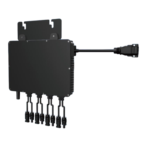
- Page 19 Product Installation 4.2.4 Port of microinverter Serial number Descriptions Microinverter AC terminal connector Microinverter DC terminal connector Wi-Fi antenna 4.2.5 Size of microinverter(mm) MR1600,MR2000,MR2400...
- Page 20 Application scenario MR1600/MR2000/MR2400 series micro-inverse products are mainly applied to roofs. The roof application scenario can consist of multiple microinverters(at least one, but no more than four), each of which can be paired with four PV modules.
- Page 21 1. Put two rail nuts into the PV modules rail, then install two M8*22 mm Phillips screws. 2. Fix the microinverter between the rail nuts and the M8*22 mm Phillips screws, and tighten the Phillips screws with a torque of 5 N· m. MR1600,MR2000,MR2400...
- Page 22 PV system. Note: (1) The grounding cable should be prepared by yourself with a recommended specification of 4 mm (2) Please ensure the microinverter is well-connected to ground. MR1600,MR2000,MR2400...
- Page 23 (1) Attention the silkscreen L/N/PE on the wire holder when inserting the crimped cable into it. (2) Ensure there is no obvious gap between the compression ring and outer jacket of AC cable at the end of the AC trunk plug and the AC cable. MR1600,MR2000,MR2400...
- Page 24 3. Connect the AC terminal plug into the AC trunk connector. When inserting, please pay attention to the direction of the interface. When you hear a clear "click" sound, it indicates well-connected. 4. Connect the AC end cable to the distribution box and wire it to the local grid. MR1600,MR2000,MR2400...
- Page 25 Step 7: Create installation map Use the installation map to record the location of microinverters. 1. Each column on the map represents a PV module, and chooses the direction of installation in the top left corner. MR1600,MR2000,MR2400...
- Page 26 (1) Connect the positive and negative DC connectors of the same PV module to the same DC input channel of the microinverter. (2) Ensure the polarity of DC connector of PV modules and DC input of microinverter, do not reverse the polarity of them to avoid damaging the microinverter. MR1600,MR2000,MR2400...
- Page 27 Product Installation 4.5.2 Commissioning ATTENTION • Before starting up the device for the first time (commissioning), Please fill in the installation specification check list in the package to check the installation process, otherwise, it may affect your after-sales service experience. MR1600,MR2000,MR2400...
- Page 28 Plant and view the Power Generation. You can check "SOFAR CLOUD User Manual" in the "My - Personal Settings - About Software - Operation Manual" page of SOFAR CLOUD APP to achieve more information.
- Page 29 Product Installation 2. Register 3. Log in and configure the network MR1600,MR2000,MR2400...
- Page 30 Product Installation 4. Create a Plant MR1600,MR2000,MR2400...
- Page 31 Product Installation 5. View the Power Generation MR1600,MR2000,MR2400...
- Page 32 Product Installation 4.5.4 Installation & connection video You can watch installation & connection video by scanning the following QR code. MR1600,MR2000,MR2400...
- Page 33 - Solid green - normal working condition. (3) Other states - Solid yellow - Insulation impedance fault. - Red flashes - wireless communication failure. - Solid red - Inverter fault, please use APP to check the detailed fault code MR1600,MR2000,MR2400...
- Page 34 ID002 Grid undervoltage the power grid. After the power grid returns to normal, the inverter automatically ID003 Grid overfrequency resumes normal operation. If the alarm is frequent, check ID004 Grid underfrequency if the grid voltage/frequency is within the acceptable MR1600,MR2000,MR2400...
- Page 35 Check if the problem is solved. ID018 The DCI sampling fault If not, please contact Grid voltage sampling fault technical support. ID020 (AC side) DC input current sampling ID024 fault BUS voltage mismatching ID032 fault Master communication ID033 fault (DC side) MR1600,MR2000,MR2400...
- Page 36 Make sure that the inverter that the ambient ID063 Module 5 overtemperature temperature is less than the upper temperature limit of the inverter. Check if the PV voltage (Voc) ID069 PV overvoltage is higher than the maximum input voltage of the inverter. MR1600,MR2000,MR2400...
- Page 37 Check to see if the PV overcurrent software problem is resolved. ID086 protection If not, contact technical Internal bus hardware support. ID098 overvoltage Inverter MOSFET hardware ID101 fault ID102 PV hardware overcurrent Output hardware ID103 overcurrent ID106 Serial number model fault MR1600,MR2000,MR2400...
- Page 38 Please use compressed air, soft cloth or soft bristle brush to clean the heat sink. Do not use water, caustic chemicals, detergents or strong detergents to clean the heat sink. MR1600,MR2000,MR2400...
- Page 39 DC connection, observe the side indicators. 2. Connect the AC connector of the replacement microinverter to the AC trunk connector. 3. Close the circuit breaker on the AC branch circuit of the microinverter to verify the working status. MR1600,MR2000,MR2400...
- Page 40 Microinverter Replacement 6.1.3 Replacement of inverters in SOFAR CLOUD 1. Make a note of the machine serial number of the new replacement microinverter. 2. Replacement in SOFAR CLOUD. Disposal If the equipment is no longer to be put into service or is to be stored for a long period of time, make sure that the packaging is intact.
- Page 41 Technical Specification Technical Specification Technical specification Model MR1600 MR2000 MR2400 DC Input Recommended PV Module Power (STC) 200 Wp to 670 Wp+ Range Voltage range 22-58 V MPPT operating 26-55 V voltage range Max. power voltage 31.5-45 V range Number of MPPT Max.
- Page 42 Relative humidity 5%~95% (non-condensing) range Max. operating <4000 m altitude Topology Isolated Degree of protection IP67 Dimensions (W*H*D) 295*210*43 mm Cooling Natural Cooling Weight 5.5 kg Communication Wi-Fi IEC/EN 61000-6-1/-3, IEC62109-1/-2, VDE4105, Standard EN50549-1, EN50549-1 (NFG) typeA, ABNT NBR 16149/50 MR1600,MR2000,MR2400...
- Page 43 Technical Specification Installation maps MR1600,MR2000,MR2400...
- Page 44 Introduction The inverter can support the grid by providing reactive power in 6 different modes by using SOFAR CLOUD. The mode 1 to 4 are for installation personnel, 5 to 6 are only shown for professionals or engineers. Take the microinverter of SOFAR MR2000 for example.
- Page 45 For example, the rated active power of SOFAR MR2000 is 2kW. If the reactive power percentage is set to 40%, the reactive power output is 2*40%= 0.8kvar. Below is the operation interface of the APP:...
- Page 46 SOFAR Monitor 8.1.4 Reactive mode 3: the reactive power of inverter will follow the change of active power By setting the four level active power load reduction point, the reactive power is calculated according to the power factor corresponding to the set active power.
- Page 47 SOFAR Monitor Parameter Explain Range Cos φ (P) Output active power at point P_P1 Optional p1 on the mode curve Cos φ (P) Output active power at point P_P2 Optional P2 on the mode curve Cos φ (P) Output active power at point...
- Page 48 SOFAR Monitor Cos φ (P)Symbol of the power factor Sgn(Cosφ)_P4 leading angle at point p4 on the mode curve Note: this mode has a voltage entry enable bit. If it is enabled, it is necessary to set the lockinv voltage percentage and lockoutv voltage percentage. When the grid voltage percentage is greater than the lockinv voltage percentage, this mode is normally enabled;...
- Page 49 SOFAR Monitor 8.1.5 Reactive mode 4: inverter reactive power continuously changes with grid voltage The reactive power is adjusted by setting the high-voltage starting point, high- voltage ending point, low-voltage starting point and low-voltage ending point of the grid voltage, in which the grid voltage changes continuously. The...
- Page 50 SOFAR Monitor Among them, the reactive power at point P1 is the maximum lagging reactive power, the reactive power at point P2 is the reactive power at the low voltage starting voltage point, the reactive power at point P3 is the reactive power at the high voltage starting voltage point, and the reactive power at point P4 is the maximum leading reactive power.
- Page 51 SOFAR Monitor 8.1.6 Reactive mode 5: inverter reactive power discontinuously changes with grid voltage The reactive power is adjusted by setting the high-voltage starting point, high- voltage ending point, low-voltage starting point and low-voltage ending point of the grid voltage, in which the grid voltage changes step by step. The...
- Page 52 SOFAR Monitor Among them, the reactive power corresponding to P1 and P4 points is the maximum reactive power point. (The two are equal in magnitude but opposite in direction) Below is the operation interface of the APP: MR1600,MR2000,MR2400...
- Page 53 SOFAR Monitor 8.1.7 Reactive mode 6: the inverter calculates the current output reactive power through constant apparent power This is, when active power does not reach 92% of the rated active power, reactive power value is fixed at 60% of the rated active power; When the active...
- Page 54 Appendix Appendix Reference wiring diagram 9.1.1 230Vac single phase output reference wiring diagram MR1600,MR2000,MR2400...
- Page 55 Appendix 9.1.2 230Vac/400Vac three-phase output reference wiring diagram MR1600,MR2000,MR2400...
- Page 56 Appendix 9.1.3 120Vac/240Vac split phase output reference wiring diagrams MR1600,MR2000,MR2400...
- Page 57 Appendix 9.1.4 120Vac/208Vac three-phase output reference wiring diagrams MR1600,MR2000,MR2400...
- Page 58 Appendix System layout diagram Accessories list diagram MR1600,MR2000,MR2400...
- Page 59 Shenzhen SOFARSOLAR Co., Ltd. 11/F, Gaoxinqi Technology Building, District 67, XingDong Community, XinAn Street, Bao’An District, Shenzhen, China SOFARSOLAR GmbH Krämerstrasse 20 72764 Reutlingen Germany Email: service.uk@sofarsolar.com Web: www.sofarsolar.com...
- Page 60 Appendix MR1600,MR2000,MR2400...
Need help?
Do you have a question about the MR1600 and is the answer not in the manual?
Questions and answers