
Subscribe to Our Youtube Channel
Related Manuals for Sofar SOFAR 3K-6KTLM-G2


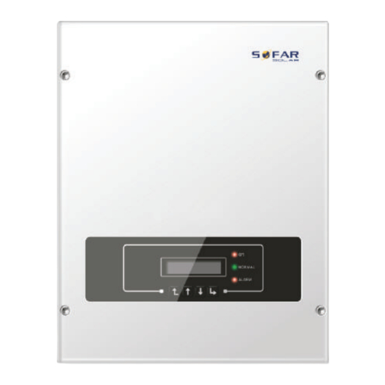
Summary of Contents for Sofar SOFAR 3K-6KTLM-G2
- Page 1 User manual PV Grid-Connected Inverter Product Model: SOFAR 3K-6KTLM-G2 (2017.10.28) ADD:Building NO.4,Antongda Industrial Park,NO.1,Liuxian Avenue, Bao’an District,Shenzhen,China Shenzhen SOFARSOLAR Co.,Ltd.
-
Page 2: Preface
This product manual describes the installation, electrical connections, commissioning, The copyright of this manual belongs to Shenzhen SOFARSOLAR Co., Ltd. Any corporation or maintenance and troubleshooting of SOFAR 3K~6KTLM-G2 inverters: individual should not plagiarize, partially copy or fully copy it (including software, etc.), and 3KTLM-G2 3.6KTLM-G2 4KTLM-G2 4.6KTLM-G2 5KTLM-G2 6KTLM-G2... -
Page 3: Table Of Contents
3 Installation Installation Process 3.2 Checking Before Installation 3.3 Tools 3.4 Determining the Installation Position 3.5 Moving the SOFAR 3K~6KTLM-G2 inverter 3.6 Installing SOFAR 3K~6KTLM-G2 inverter 4 Electrical Connections Electrical connection 4.2 Connecting PGND Cables 4.3 Connecting DC Input Power Cables 4.4 Connecting AC Output Power Cables... -
Page 4: Basic Safety Information
Installation requirements Basic safety information Please install inverter according to the following section. Fix the inverter on an appropriate objects with enough load bearing capacity (such as walls, PV racks etc.), and ensure that inverter is vertical placed. Choose a place suitable for installing electrical devices. And assure there is enough fire exit space, convenient for maintenance. -
Page 5: Symbols And Signs
Please do not continue to stay around the inverter in less than 20 cm when inverter is working. Danger Please read this manul before install SOFAR 3K~6KTLM-G2. 1.2 Symbols and signs Safety symbols This indicates the degree of protection of the equipment according to IEC standard 70-1 (EN 60529 June 1997). -
Page 6: Product Characteristics
Product characteristics Figure2-2 Front view and left view dimensions Outlines of this chapter Product dimensions It introduces the field of use, and the overall dimensions of SOFAR 3K~6KTLM-G2 inverters. Function description It introduces how SOFAR 3K~6KTLM-G2 inverters work and the function modules inside. -
Page 7: Function Description
Labels on the equipment: Electrical block diagram Figure2-4 Electrical block diagram Solar Grid-tied Inverter SOFAR 6KTLM-G2 Max.DC input Voltage Operating MPPT voltage range 90~580V Max. Input current 2x11A Max. PV lsc 2x13.2A Nominal Grid Voltage 230V Max. Output Current 27.3A... -
Page 8: Installation
Check the outer packing materials for damage, such as holes and cracks. If any damage is found, do not unpack the SOFAR 3K~6KTLM-G2 and contact the dealer as soon as possible. You are advised to remove the... -
Page 9: Tools
Operators wear Recommend drill dia. Screwdriver wiring 3.4 Determining the Installation Position Determine an appropriate position for installing the SOFAR 3K~6KTLM-G2 inverter. Comply with the following requirements when determining the installation position: Removal tool Remove PV terminal Figure3-2 Installation Requirements... - Page 10 Moving the SOFAR 3K~6KTLM-G2 inverter This topic describes how to move the SOFAR 3K~6KTLM-G2 to the installation position horizontally Step 1 Open the packaging, insert hands into the slots on both sides of the inverter and hold the handles, as shown in Figure 3-3 and Figure 3-4.
-
Page 11: Installing Sofar 3K~6Ktlm-G2 Inverter
4.6KVA and max output of PV system is 13.8KVA. rear panel to ensure safety. SOFAR 3K~6KTLM-G2 has 2 MPP trackers, all PV modules connected to the Step 5 You can secure the inverter to the rear panel and protect if from stealing by installing... -
Page 12: Connecting Pgnd Cables
4.2 Connecting PGND Cables Figure4-4 Ground terminal composition Connect the inverter to the grounding electrode using protection ground (PGND) cables for grounding purposes. The inverter is transformer-less, requires the positive pole and negative pole of the PV array are NOT grounded. Otherwise it will cause inverter failure. In the PV power system, all non current carrying metal parts (such as: PV module frame, PV rack, combiner box enclosure, inverter enclosure) should be connected to earth. -
Page 13: Connecting Ac Output Power Cables
Step 6 Reinstall cable glands on positive and negative connectors and rotate them against the insulation covers. Connect the SOFAR 3K~6KTLM-G2 to the AC power distribution frame (PDF) or power grid Step 7 Insert the positive and negative connectors into corresponding DC input terminals of using AC output power cables. - Page 14 AC wire connections procedure: Table4-2 Recommended AC output cable specifications Step 1 Select appropriate cables according to Table 4-2, Remove the insulation layer of the AC output cable using a wire stripper according to the figure shown below: A: 30~50mm B: Model 3KTLM-G2 3.6KTLM-G2 4KTLM-G2 4.6KTLM-G2 5KTLM-G2 6KTLM-G2...
-
Page 15: Connecting Communications Cables
Step 4 Secure the locking cable gland clockwise, shown as below: make sure that all the wires Step 2 Unlock the waterproof cable gland, remove the stopper in the waterproof connector; are securely connected; Figure 4-18 Step 5 Connect the AC output connector to the output wiring terminal of inverter, rotate the AC connector clockwise until the fastener reaches its designated position, as shown below: Figure 4-15 Figure 4-16... -
Page 16: Wifi/Gprs Module Installation Procedure
Table4-4 functional description of the communication terminals Figure 4-22 DRM0 Connected in parallel DRM0 Figure 4-20 4.6 WIFI/GPRS module installation procedure: step1: remove wifi/GPRS waterproof cover using screw driver. step2: install WIFI/GPRS module stpe3: fasten WIFI/GPRS module using screws. Figure 4-23 Step 5 Insert the terminal as per the printed label, and then tighten the screws to fix the waterproof cover, rotate the cable gland clockwise to fasten it securely. -
Page 17: Communication Method
Figure 4-27 4.6 Communication method SOFAR 3K~6KTLM-G2 gird-connected inverters offer RS485 (standard) and Wi-Fi (optional) communication modes: Radio ripple Publlc Grid control receiver A. Communication between one inverter and one PC: 1. RS485 Refer to the figure shown below, connect the TX+ and TX- of the inverter to the TX+ and TX- of the RS485→... -
Page 18: Commissioning Of Inverter
Step 2: Turn ON the AC circuit breaker. Inverter States Light When the DC power generated by the solar array is adequate, the SOFAR 3K~6KTLM-G2 Warning Light inverter will start automatically. Screen showing “normal” indicates correct operation. Step 3: Choose the correct country code. (refer to section 6.3 of this manual) -
Page 19: Standard Interface
6.2 Standard Interface When power-on, LCD interface displays INITIALIZING, refer below picture. Initializing… when control board successfully connected with communication board, the LCD display the current state of the inverter display as shown in the figure below. , Wait 10s Waiting States,Countdown 10S (depends country code,some are 60s) Check... -
Page 20: Main Interface
Inverter states includes: wait、check、normal、fault and permanent 1.Enter Setting Wait : Inverter is waiting to Check State at the end of reconnection time. In this state, grid voltage value is between the max and min limits and so on; If not, Inverter will go to Fault 13. - Page 21 4. Set Country 6. Relay Command Users press “Back” button to enter “1.Enter setting” interface, Press OK button to enter main Users press “Back” button to enter “1.Enter setting” interface, Press ”OK“ button to enter setting interface. Enter “4.Set Country Code” by pressing “Up” button Or “Down” button, main setting interface.
- Page 22 10. Set Inputmode for wrong passwords. Press “Back” button and rekey in the correct passwords. “Success” will Input mode selection: SOFAR 3K~6KTLM-G2 inverter has 2 MPPT channels, the 2 MPPT can be displayed if setting successfully. operate independently, also can operate in parallel. If the PV strings are connected in parallel .Insulation Resistance...
- Page 23 . Reactive Power Step 5:Then the Auto Test will start automatically, Press “down” to see the test results Users press “ Back button to enter “1.Enter Setting” interface, Press OK button to enter ” “ ” Testing 59.S1... main setting interface.Enter “17.Set Reactive” by pressing “Up” button or“Down”button, press “OK”...
- Page 24 Press “Down” button to see the test results Test 59.S1 OK! 81>S2:51.5Hz 89ms Press “Down” button to see the test results Wait for another test 59.S1:253V 183ms Testing 81<S1... Wait for another test Wait Testing 59.S2... Test 81<S1 OK! Wait Press “Down”...
- Page 25 Testing 81<S1... EventID NO. Press “OK” Wait 2013-10-31 16:42:16 Happening time Test 81<S1 OK! (C) “SystemInfo” Interface as below: Press “Down” button to see the test results 81<S1:49.5Hz85ms 3.SystemInfo Wait for another test 1.Inverter Type 7.Relay Command Testing 81<S2... 2.Serial Number 8.
-
Page 26: Update Software Online
6. Input Mode Press “Back” button and “Up” or “Down” button to enter “3. System Info” interface, then SOFAR 3K~6KTLM-G2 inverters offer software upgrade via SD card to maximize inverter Press “OK” button to enter into system information checking interface, then press “Up” or performance and avoid inverter operation error caused by software bugs. - Page 27 Step 3 The SD card reader must be ready by the users, so that SD card so easy to establish the connection with the computer. Step 4 SOLAR will send the Software code to the user who needs to update. After user receive the file, please decompressing file and cover the original file in SD card.
-
Page 28: Trouble Shooting And Maintenance
PVUVP Check whether too few PV modules are series ID05 The input voltage is too low connected in a PV string, thus the voltage(Vmp) of the PV string is lower than the minimum operating voltage of inverter. If yes, adjust the number of series Trouble shooting and maintenance connected PV modules to increase the voltage of the PV string to fit the input voltage range of inverter. - Page 29 ID66 ID26 UnrecoverBusOVP The bus voltage is too BusOVP The bus voltage Is too high ID26-ID27 are internal faults of inverter, turn OFF h i g h , a n d h a s c a u s e the “DC switch”, wait for 5 minutes, then turn ON the “DC switch”.
-
Page 30: Maintenance
OFF. Wait at least for 5 minutes before the cleaning. Outlines of this chapter This topic lists the technical specifications for all SOFAR 3K~6KTLM-G2 inverters. Inverter cleaning 8.1 Input parameters (DC) Please clean the inverter with an air blower, a dry & soft cloth or a soft bristle brush. Do NOT clean the inverter with water, corrosive chemicals, detergent, etc. -
Page 31: General Data
97.8% Weighted eff. (EU/CEC) 97.2% 97.3% Shenzhen SOFARSOLAR Co., Ltd offers 5 years product warranty for Sofar 3K~6KTLM-G2 <1w Self-consumption at night inverters from date of installation. However the warranty period can’t exceed 66 months from the date of delivery of the inverter. During the warranty period, Shenzhen SOFARSOLAR Feed-in start power Co., Ltd guarantees normal operation of the inverter.
Need help?
Do you have a question about the SOFAR 3K-6KTLM-G2 and is the answer not in the manual?
Questions and answers