Sofar HYD 3000-EP User Manual
Hide thumbs
Also See for HYD 3000-EP:
- User manual (104 pages) ,
- Installation and operating manual (107 pages) ,
- User manual (85 pages)
Table of Contents
Advertisement
Quick Links
Advertisement
Table of Contents

Subscribe to Our Youtube Channel
Related Manuals for Sofar HYD 3000-EP


Summary of Contents for Sofar HYD 3000-EP
- Page 1 HYD 3000 ~ 6000-EP USER MANUAL...
-
Page 3: Table Of Contents
HYD 3000 ~ 6000-EP USER MANUAL CONTENT Preface ............................IV 1. Basic safety information ....................2 1.1. Safety instructions ....................2 1.2. Symbols and signs ....................7 2. Product characteristics ....................10 2.1. Product information .................... 10 2.2. Size description ..................... 11 2.3. - Page 4 HYD 3000 ~ 6000-EP USER MANUAL 4.3. PV Connection ....................... 25 4.4. Battery Connection ....................27 4.5. Load connection ....................28 4.6. Grid connection ....................30 4.7. System electrical topology ................32 4.8. External communication interface ..............35 5. Buttons and indicator lights ..................47 5.1.
- Page 5 (including software, ect . ), and no reproduction or distribution of it in any form or by any means. All right reserved. SOFAR reserves the right of final interpretation. This manual is subject to change according to user’s or customer’s feedback. Please check our website at http://www.sofarsolar.com for latest version.
-
Page 6: Preface
This product manual describes the installation, electrical connections, commissioning,maintenance and troubleshooting of HYD 3000/3680/ 4000/4600/5000/5500/6000-EP inverters: HYD 3000-EP HYD 3680-EP HYD 4000-EP HYD 4600-EP HYD 5000-EP HYD 5500-EP HYD 6000-EP Keep this manual where it will be accessible at all times. - Page 7 HYD 3000 ~ 6000-EP USER MANUAL Symbols Used This manual is provides safety operation information and uses the symbol in order to ensure personal and property security and property security and use inverter efficiently when operating the inverter.You must understand these emphasized information to avoid the personal injury and property loss.
-
Page 8: Basic Safety Information
HYD 3000 ~ 6000-EP USER MANUAL Basic safety information 1.1. Safety instructions Read and understand the instructions of this manual, and be familiar with relevant safety symbols in this chapter, then start to install and troubleshoot the equipment. According to the national and state requirements, before connecting to the electrical grid, you must get permission from the local electrical grid operation can only be performed by qualified electrical engineer. - Page 9 HYD 3000 ~ 6000-EP USER MANUAL the manual.For safety reason only a qualified electrician, who has received training and / or has demonstrated skills and knowledge in construction and in operation of this unit, can install this inverter. Shenzhen SOFARSOLAR Co. , Ltd.does not take any responsibility for the property destruction and personal injury because of any incorrect use.
- Page 10 HYD 3000 ~ 6000-EP USER MANUAL The picture is only for reference,please make the object as the standard. Note Electric connection Please comply with all the current electrical regulations about accident prevention in dealing with the solar inverter. Before the electrical connection, make sure to use opaque material to cover the PV modules or to disconnect PV array DC switch.
- Page 11 Attention inverter to electrical grid. It’s forbidden to remove the tamper evident label, or open the inverter.Otherwise Sofar will not Note provide warranty or maintenance! Operation Touching the electrical grid or the terminal of the equipment may lead to electrocution or fire! ...
- Page 12 HYD 3000 ~ 6000-EP USER MANUAL Maintenance and repair Before any repair work, turn OFF the AC circuit breaker between the inverter and electrical grid first, then turn OFF the DC switch. After turning OFF the AC circuit breaker and DC switch, wait for 5 minutes at least before carrying Danger out any maintenance or repair work.
-
Page 13: 1.2. Symbols And Signs
HYD 3000 ~ 6000-EP USER MANUAL Electromagnetic radiation from inverter may be harmful to health! Please do not continue to stay around the inverter in Danger less than 20 cm when inverter is working. 1.2. Symbols and signs ... - Page 14 HYD 3000 ~ 6000-EP USER MANUAL Signs on the inverter There are some symbols which are related to security on the inverter.Please read and understand the content of the symbols, and then start the installation. This symbol indicates a hazardous situation which could result in injuries, if not avoided.
- Page 15 HYD 3000 ~ 6000-EP USER MANUAL Positive pole and negative pole of the input voltage (DC). This side up, HYD 3000/3680/4000/4600/5000/5500/ 6000-EP inverter must always be transported, handled and stored in such a way that the arrows always point upwards.
-
Page 16: Product Characteristics
HYD 3000 ~ 6000-EP USER MANUAL Product characteristics 2.1. Product information HYD 3000/3680/4000/4600/5000/5500/6000-EP inverter is a single- phase photovoltaic energy storage inverter integrating grid-connected photovoltaic inverter and battery energy storage. The HYD 3000/3680/4000/4600/5000/5500/6000-EP inverter has a variety of built-in operating modes to suit the diverse user needs. The HYD 3000/3680/4000/4600/5000/5500/6000-EP inverter can provide a complete solution in the period of rising energy costs such as oil and coal, the energy subsidy of photovoltaic grid-connected system keeps... -
Page 17: Size Description
HYD 3000 ~ 6000-EP USER MANUAL 2.2. Size description ① Front view ② left view ③ Bracket Fig.2-2 Size chart 2.3. Function characteristics The HYD 3000/3680/4000/4600/5000/5500/6000-EP energy storage inverters allow up to 10% overloading to maximize power output, and the Uninterruptible Power Supply (UPS) mode can support inductive loads such as air conditioners or refrigerators with an automatic switchover time of less than 10 milliseconds. -
Page 18: Electrical Block Diagram
HYD 3000 ~ 6000-EP USER MANUAL Smart monitoring, RS485/WiFi/Bluetooth/GPRS(Optional) 2.4. Electrical block diagram Fig.2-3 Electrical block diaram... -
Page 19: Installation
HYD 3000 ~ 6000-EP USER MANUAL Installation Installation notes Do NOT install the HYD 3000/3680/4000/4600/5000 /5500/6000-EP on flammable material. Do NOT install the HYD 3000/3680/4000/4600/5000 /5500/6000-EP in an area used to store Flammable or Danger explosive material. The enclosure and heat sink are very hot while the inverter is working, therefore do NOT install the HYD 3000/3680/4000/4600/5000/5500/6000-EP in places Caution... -
Page 20: Product Overview
HYD 3000 ~ 6000-EP USER MANUAL such as holes and cracks.If any damage is found, do not unpack the HYD 3000/3680/4000/4600/5000/5500/6000-EP and contact the dealer as soon as possible.You are advised to remove the packing materials within 24 hours before installing the HYD 3000/3680/4000/4600/5000 /5500/6000 -EP inverter. -
Page 21: Tools
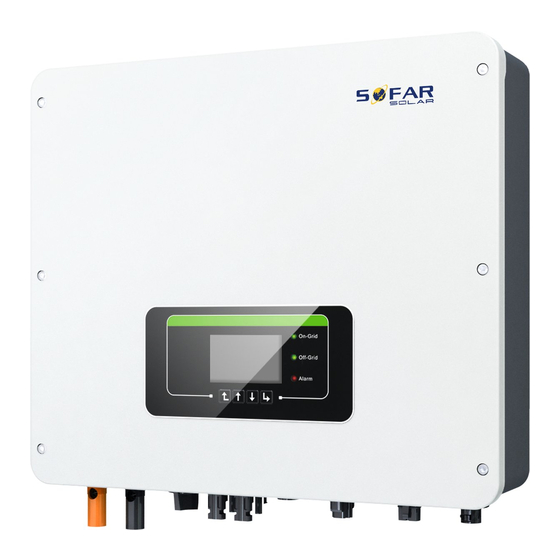
HYD 3000 ~ 6000-EP USER MANUAL Fig. 3-2 HYD 3000/3680/4000/4600/5000/5500/6000-EP inverter overview Table 3-2 HYD 3000/3680/4000/4600/5000/5500/6000-EP inverter overview Battery input terminals Link Port 1 DC switch PV input terminals Grid connection port USB/WiFi Load connection port Link Port 0 3.3. Tools Prepare tools required for installation and electrical connections. - Page 22 HYD 3000 ~ 6000-EP USER MANUAL Tool Model Function Removal tool Remove PV terminal Wire stripper Strip wire 4mmAllen Turn the screw to connect Wrench rear panel with inverter. Crimping tool Used to crimp power cables Multi-meter Used to check grounding With open larger...
-
Page 23: Installation Environment
HYD 3000 ~ 6000-EP USER MANUAL 3.4. Installation Environment Choose a dry, clean, and tidy place, convenient for installation. Ambient temperature range: -25℃ ~ 60℃. Relative humidity: 0 ~ 100% (non-condensed). HYD 3000/3680/4000/4600/5000/5500/6000-EP inverter shall be installed in a well-ventilated place. No flammable or explosive materials close to HYD 3000/3680/4000/ 4600/5000/5500/6000-EP inverter. -
Page 24: Unpacking The Inverter
HYD 3000 ~ 6000-EP USER MANUAL ④ ⑥ ⑤ ⑦ Fig.3-3 Installation Position of HY 3000/3680/4000/4600/5000/5500/6000-EP inverter 3.6. Unpacking the inverter Step 1 Open the packaging, insert hands into the slots on both sides of the inverter and hold the handles, as shown in Fig. 3-4. ①... -
Page 25: Installation Of The Inverter
HYD 3000 ~ 6000-EP USER MANUAL installation position. To prevent device damage and personal injury, keep balance when moving the inverter because the inverter is heavy. Do not put the inverter with its wiring terminals contacting the floor because the power ports and signal ports are not designed to support the weight of the inverter. - Page 26 HYD 3000 ~ 6000-EP USER MANUAL in Figure 3-5⑤. ② ① ③ ④ ⑤ Fig.3-5 Installing HYD 3000/3680/4000/4600/5000/5500/6000-EP...
-
Page 27: Electrical Connections
≤ 580V. The connected PV modules must have an IEC 61730 Class A ratin. Table 4-1 Relevant current parameters of each model IscPV(absolute Maximum output over Model maximum) current protection HYD 3000-EP 18A/18A Copyright © Shenzhen SOFARSOLAR Co. , Ltd。... -
Page 28: Wire Instructions
HYD 3000 ~ 6000-EP USER MANUAL HYD 3680-EP HYD 4000-EP HYD 4600-EP 20. 9A HYD 5000-EP 21. 7A HYD 5500-EP HYD 6000-EP 27. 3A The DVC is the voltage of a circuit which occurs continuously between any two live part in the worst-case rated operating condition when used Note as intended. -
Page 29: Connecting Pgnd Cables
HYD 3000 ~ 6000-EP USER MANUAL +:Connect the positive Industry electrode of photovoltaic Conductor common cell cross-sectional outdoor -:Connect the negative photovoltaic area:4mm ~6mm electrode of photovoltaic cable cell Conductor Outdoor cross-sectional Load multi-core area:6mm ~ copper cable 10mm Conductor Outdoor cross-sectional multi-core... - Page 30 HYD 3000 ~ 6000-EP USER MANUAL protecton ground points inverters equipotential connected. The PGND cables are prepared (≥4mm²outdoor power cables are recommended for grounding purposes),the color of cable should be yellow-green. Procedure: Step 1 Remove the insulation layer with an appropriate length using a wire stripper, as shown in Fig.
-
Page 31: Pv Connection
HYD 3000 ~ 6000-EP USER MANUAL Note: L2 is 2 to 3mm longer than L1 ① ② 1. Screw 2. OT Terminal 3. Tapped hole ③ Fig. 4-1 Connecting PGND cable 4.3. PV Connection Procedure: Step 1 Select the appropriate cable type and specifications according to the table4-3. - Page 32 HYD 3000 ~ 6000-EP USER MANUAL cannot be pulled out by force less than 400 N, as shown in Fig. 4-2②. Step 4 Insert crimped power cables into corresponding housings until you hear a "click" sound. The power cables snap into place, as shown in Fig.
-
Page 33: Battery Connection
HYD 3000 ~ 6000-EP USER MANUAL Disconnect PV connectors ⑦ Fig. 4-2 Connect PV 4.4. Battery Connection Procedure: Step 1 Select proper battery cable types and specifications based on Table 4-3.Remove cable glands from the positive and negative connectors. Step 2 Remove the insulation layer of the positive and negative battery cables using a cable disconnector, as shown in the figure. -
Page 34: Load Connection
HYD 3000 ~ 6000-EP USER MANUAL ③ ① ② ⑤ ⑥ ④ Fig.4-3 Install battery connection 4.5. Load connection Procedure: Step 1 Select appropriate cables according to Table4-3, Remove the insulation layer of the load output cable using a wire stripper according to the Fig. - Page 35 HYD 3000 ~ 6000-EP USER MANUAL shown in the Fig. 4-4③: Connect the yellow-green wire to the hole labeled "PE", fasten the wire using an Cross screwdriver; Connect the brown wire to the hole labeled "L", fasten the wire using an Cross screwdriver;...
-
Page 36: Grid Connection
HYD 3000 ~ 6000-EP USER MANUAL ④ ③ ⑤ ⑥ Hold the button to unlock ⑦ Fig. 4-4 Load connection 4.6. Grid connection The inverter is equipped with an integrated residual current monitoring unit.When the inverter detects that the residual current exceeds 300mA, the connection to the power grid will be quickly disconnected. - Page 37 HYD 3000 ~ 6000-EP USER MANUAL leakage action current is required to be ≥ 300mA. Procedure: Step 1 Select the appropriate cable type and specifications according to the table4-3. Refer to Fig. 4-5① for processing wire. Step 2 Pass the wire through the terminal, as shown in Fig. 4-5②. Step 3 According to the mark, lock the wire into the keyhole on the terminal and tighten it with the hexagon socket wrench, as shown in Fig.
-
Page 38: System Electrical Topology
Fig. 4-5 Grid connection 4.7. System electrical topology SOFAR has already integrated RCMU (residual current monitoring unit) inside inverter. If an external RCD is required, a type-A RCD with rated residual current of 100mA or higher is suggested. EP series household energy storage system is mainly composed of PV... - Page 39 HYD 3000 ~ 6000-EP USER MANUAL generator modules, and smart meters /CT. The inverters AC GRID and AC LOAD are wired with different N and PE wires depending on the regulatory requirements in different regions. System 1: N and PE lines are wired separately in the distribution box The wiring method in Figure 4.6 is applicable to areas without special requirements for distribution system wiring.
- Page 40 HYD 3000 ~ 6000-EP USER MANUAL 11. NeutralPointGrounding Enable Disable System 2: N and PE lines are connected together in the distribution The wiring method in Figure 4-7 is applicable to areas where N and PE are connected together in the distribution box, such as Australia, South Africa, New Zealand, etc.
-
Page 41: External Communication Interface
HYD 3000 ~ 6000-EP USER MANUAL Install Residual current device (RCD)in front of the load RCD is necessary for critical load, but optional for normal load. In off-grid mode, the Entry master switch is unprotected and load leakage could lead to shock danger. ... - Page 42 HYD 3000 ~ 6000-EP USER MANUAL Fig. 4-8 USB/WIFI communication interface Table 4-4 Interface description Definition Function Note GND. S USB power - The USB power supply is 5V/1A; USB data + Cannot be used for external USB data - device charging VBUS USB power +...
- Page 43 HYD 3000 ~ 6000-EP USER MANUAL WiFi/GPRS shall be affixed to the package box and the WiFi/GPRS. Register your system at the website home. solarmanpv. com.For this, enter the serial number found on the stick logger. Installers use the portal at pro. solarmanpv. com. To download the app, search for “SOLARMAN”...
- Page 44 HYD 3000 ~ 6000-EP USER MANUAL inverter CAN be adaptive to 485-2TX+ RS485 differential signal + lithium battery provide CAN communica- tion and RS485 communica 485-2TX- RS485 differential signal – -tion 485-1TX+ RS485 differential signal + Wired monitoring inverter cascade monitoring 485-1TX- RS485 differential signal –...
- Page 45 HYD 3000 ~ 6000-EP USER MANUAL ⑤ ④ Fig. 4-11 COM interface 1. RS485(Wired monitoring or inverter cascade monitoring) Refer to the figure 4-12 shown below, connect the RS485+ and RS485- of the inverter to the TX+ and TX- of the RS485→USB adapter, and connect the USB port of the adapter to the computer.
- Page 46 HYD 3000 ~ 6000-EP USER MANUAL Fig. 4-13 RS485 connection(cascade of monitoring between inverters) 2. Logic interface The logic interface pin definitions and circuit connections are as follows: Logic interface pin are defined according to different standard requirements (a)Logic interface for AS/NZS 4777. 2:2015, also known as inverter demand response modes (DRMs).
- Page 47 HYD 3000 ~ 6000-EP USER MANUAL The inverter can be connected to a RRCR (Radio Ripple Control Receiver) in order to dynamically limit the output power of all the inverters in the installation. Fig. 4-14 Inverter – RRCR Connection Table 4-7 Function description of the terminal Pin NO.
- Page 48 HYD 3000 ~ 6000-EP USER MANUAL interface. Fig. 4-15 Inverter – RRCR Connection Table 4-9 Function description of the terminal Pin NO. Pin name Description Connected to (RRCR) Relay contact 1 input K1 - Relay 1 output K1 - Relay 1 output Table 4-10 The inverter is preconfigured to the following RRCR power levels, close is 1, open is 0 Active Power...
- Page 49 HYD 3000 ~ 6000-EP USER MANUAL ① ② ③ ④ Fig. 4-16 Meter If you need to use the CT alone, attach the CT to PIN13 and PIN14. There are two ways to get grid current information : Table 4-11 Plan A:CT; Plan B: Meter +CT Plan A:CT Plan B:Meter +CT CT(3000:1)120A/40mA...
- Page 50 HYD 3000 ~ 6000-EP USER MANUAL Fig.4-17 Electrical connections (Plan A:CT)
- Page 51 HYD 3000 ~ 6000-EP USER MANUAL Fig.4-18 Electrical connections (Plan B:Meter +CT ) 4. Feed-in limit function The feed-in limit function can be used to limit the power fed back into the grid.In order to achieve this function, power measurement devices must be installed according to the system.
- Page 52 HYD 3000 ~ 6000-EP USER MANUAL 4. 8. 3 Link 0&1-Cascade communication interface ① ② ③ Fig. 4-19 Link Port When using the parallel system, the inverter settings and notes please refer to this manual<6. 3. 2 Advanced setting→6. Parallel setting>. Note(AC LOAD is also parallel for parallel machines): The first and last inverters need to be connected with 8Pin connection terminals.
-
Page 53: Buttons And Indicator Lights
HYD 3000 ~ 6000-EP USER MANUAL switch; All AC LOAD should be Shared another total air switch . In parallel mode, each inverter must ground with the PGND cable. (refer to 4.2) Fig. 4-20 parallel system Buttons and indicator lights Fig. -
Page 54: Buttons
HYD 3000 ~ 6000-EP USER MANUAL 5.1. Buttons press “Back” to the previous screen or enter the main interface. press “Up” to the upper menu option or value plus 1. press “Down” to the lower menu option or value minus 1. ... -
Page 55: Operation
HYD 3000 ~ 6000-EP USER MANUAL Operation 6.1. Double Check Please double check the following before operation. Inverter is firmly fastened to the mounting bracket on the wall. PV+/PV- wires are firmly connected, polarity and voltage are correct. BAT+/BAT- wires are firmly connected, polarity and voltage are correct. - Page 56 HYD 3000 ~ 6000-EP USER MANUAL Switch ON the battery.Turn ON DC isolator between battery & inverter. Turn ON AC circuit breaker between the inverter GRID port & GRID. Turn ON AC circuit breaker between the inverter LOAD port & critical load.
-
Page 57: Menu
HYD 3000 ~ 6000-EP USER MANUAL 1. Battery Address 1. Battery Capacity 2. Battery Charge Current 2. Battery Nominal Voltage Limit 3. Battery Discharge 3. Battery Cell Type Current Limit 4. Battery Charge Current 4. Battery DOD(EOD) Limit 5. Battery Discharge Current Limit 6. - Page 58 HYD 3000 ~ 6000-EP USER MANUAL Main interface Grid Output Information Down↓ Grid(V) ....***. *V AC Power ....**. **kW Frequency.
- Page 59 1. Select safety 3. Safety Param regulations 2. Select USB file To enable this feature, please contact the Sofar technical support . Note Copyright © Shenzhen SOFARSOLAR Co. , Ltd。...
- Page 60 HYD 3000 ~ 6000-EP USER MANUAL Energy Storage Mode 4. Energy Storage Mode 1. Self-use Mode 2. Time-of-use Mode 3. Timing Mode 4. Passive Mode 5. Peak shaving mode Self-use Mode In Self-use mode, inverter will automatically charge & discharge the battery.
- Page 61 HYD 3000 ~ 6000-EP USER MANUAL If PV generation + Battery < LOAD consumption, inverter will import power from the grid. Time-of-use Mode If electricity is more expensive in high demand time (peak rate) & electricity is much cheaper in low demand time (off-peak rate). You can select an off-peak period to charge your battery.Outside the off-peak charge period, inverter is working in Auto Mode.
- Page 62 22 h 00 m Charge End 05 h 00 m Charge Power 02000 W DisCharge Start 14 h 00m DisCharge End 16 h 00m DisCharge Power 02500 W Passive Mode For more detailed information, please ask representative of SOFAR to...
- Page 63 HYD 3000 ~ 6000-EP USER MANUAL get a copy of passive mode communication protocol. 4. Passive Mode Success Peak shaving mode 5. Peak shaving mode Peak Shaving Mode Priority Buy Power 0100W Auto Test (ONLY for Italian Market) 5. Auto Test 1.
- Page 64 HYD 3000 ~ 6000-EP USER MANUAL Test 81>S1 OK! Wait ↓ Testing 81>S2… Wait ↓ Test 81>S2 OK! Wait ↓ Testing 81<S1. . . Wait ↓ Test 81<S1 OK! Wait ↓ Testing 81<S2. . . Wait ↓ Test 81<S2 OK! Press “Ok”...
- Page 65 HYD 3000 ~ 6000-EP USER MANUAL 27. S2 threshold 34. 5V 200ms Press “Down” ↓ 27. S2: 227V 205ms Press “Down” ↓ 81>. S1 threshold 50. 5Hz 100ms Press “Down” ↓ 81>. S1 49. 9Hz 103ms Press “Down” ↓ 81>. S2 threshold 51.
- Page 66 HYD 3000 ~ 6000-EP USER MANUAL 6. PV Input Mode Success Parallel Independent Success EPS Mode 7. EPS Mode 1. Enable 1. EPS Mode Control 2. Disable If PV generation > LOAD generation LOAD consumption (ΔP > 100W), inverter consumption, inverter wont’ charge will charge battery.
- Page 67 HYD 3000 ~ 6000-EP USER MANUAL 2. Baud Rate 6. 3. 2 Advanced setting 2. Advanced Settings Input0001 1. Battery Parameter 2. Feed-in Limitation 3. IV Curve Scan 4. Logic Interface 5. Factory Reset 6. Parallel settings 7. Reset Bluetooth 8.
- Page 68 HYD 3000 ~ 6000-EP USER MANUAL 20%. 5. Discharge Depth Discharge Depth Discharge Depth EPS 80% EPS Safety Buffer Set Feed-in Limit The user can enable “Feed-in Limit” to limit the max export power to grid. Reflux Power set is desired max export power to grid.Refer to 4. 7. 2 for connection of the system when using Feed-in Limit function.
- Page 69 HYD 3000 ~ 6000-EP USER MANUAL inverter logic interface connection for details. 4. Logic Interface Enable Disable Factory Reset 1. Clear Energy Data 5. Factory Reset 2. Clear Events 3. Factory Reset Clean the inverter of the total power generation. Cancel Please 1.
- Page 70 HYD 3000 ~ 6000-EP USER MANUAL (3) Parallel Address: Set the parallel address. Each inverter needs to set a parallel address, and the parallel address in a parallel system cannot be repeated. ( NOTE:The parallel address is different from the communication address used for monitoring.
- Page 71 HYD 3000 ~ 6000-EP USER MANUAL (1) Set "Enable".If the PCC is not connected, "ID105" will appear; (2) Set "Enable", connect PCC.If the communication is not properly set, an "ID105" fault will occur.Therefore, the user needs to set the communication protocol of the PCC to n. 1 or n. 2, and the communication address to 1.
- Page 72 HYD 3000 ~ 6000-EP USER MANUAL Import... ***KWH Charge...***KWH Discharge..***KWH Year Down↓ PV ....***KWH Load .
- Page 73 HYD 3000 ~ 6000-EP USER MANUAL PV Input Mode Energy Storage Mode RS485 Address EPS Mode Down Inverter Info (4) IV Curve Scan Logic Interface Down Inverter Info (5) Power Factor Feed-in Limit Insulation resistance 2. Battery Info Batl1 Information(1) Battery Type Battery Capacity Discharge Depth...
- Page 74 HYD-EP_ARM. bin, HYD-EP_DSPM. bin, HYD-EP_DSPS. bin. Step 1 Insert the usb flash drive into the compute. Step 2 SOFAR will send the Software code to the user who needs to update.After user receive the file,please decompressing file and cover the original file in usb flash drive.
- Page 75 HYD 3000 ~ 6000-EP USER MANUAL Step 4 Then turn on DC switch. Step 5 6. Software Update Input password OK Input 0715 Start Update Updating DSP1 Updating DSP2 Updating ARM Step 6 If the following errors occur, please upgrade again. If this continues many times, contact technical support for help.
-
Page 76: Troubleshooting
HYD 3000 ~ 6000-EP USER MANUAL Troubleshooting This section contains information and procedures for solving possible problems with the inverter. This section help users to identify the inverter fault. Please read the following procedures carefully: Check the warning, fault messages or fault codes shown on the ... - Page 77 HYD 3000 ~ 6000-EP USER MANUAL screen,the red light will be on,and the fault can be found in the history of the fault.For the machine installed with WiFi/GPRS, the alarm information can be seen on the corresponding monitoring website, and can also be received by the APP on the mobile phone.
- Page 78 HYD 3000 ~ 6000-EP USER MANUAL operator. Charge Leakage ID005 GFCI Fault OVRT function is ID006 OVRT fault faulty LVRT function is ID007 LVRT fault faulty Island protection ID008 IslandFault error Transient ID009 GridOVPInstant1 overvoltage of grid voltage 1 Transient ID010 GridOVPInstant2 overvoltage of...
- Page 79 HYD 3000 ~ 6000-EP USER MANUAL Error in dc component ID023 HwADFaultDCV sampling of load voltage Dc input current ID024 HwADFaultIdc sampling error ConsistentFault_GFC Leakage current ID029 consistency error ConsistentFault_Vgri Grid voltage ID030 consistency error ID033 SpiCommFault(DC) communication error (DC) ID034 SpiCommFault(AC) communication...
- Page 80 HYD 3000 ~ 6000-EP USER MANUAL Check whether the CT ID045 CTDisconnect CT error wiring is correct. Please check whether the ID048 FanFault FanFault fan 1 of inverter is running normally. Battery ID049 TempFault_Bat temperature protection Radiator 1 TempFault_HeatSin ID050 temperature protection Radiator 2...
- Page 81 HYD 3000 ~ 6000-EP USER MANUAL Module 3 ID061 TempFault_Inv3 temperature protection Unbalanced bus ID065 VbusRmsUnbalance voltage RMS The transient Internal faults of inverter, VbusInstantUnbalan value of bus switch OFF inverter, wait ID066 voltage is for 5 minutes, then switch unbalanced ON inverter.Check whether the problem is...
- Page 82 HYD 3000 ~ 6000-EP USER MANUAL overvoltage If no, please contact technical support. Inverter bus voltage ID073 SwBusInstantOVP instantaneous value software overvoltage Battery overcurrent ID081 SwBatOCP software protection Dci overcurrent ID082 DciOCP protection Output ID083 SwOCPInstant instantaneous current protection BuckBoost ID084 SwBuckBoostOCP software flow...
- Page 83 HYD 3000 ~ 6000-EP USER MANUAL PV hardware ID102 HwPVOCP overflows Ac output ID103 HwACOCP hardware overflows Overload ID110 Overload1 protection 1 Please check whether the Overload ID111 Overload2 inverter is operating under protection 2 overload. Overload ID112 Overload3 protection 3 Make sure the inverter is installed where there is no direct sunlight.
- Page 84 HYD 3000 ~ 6000-EP USER MANUAL Permanent Bus ON inverter.Check ID130 unrecoverBusOVP overvoltage failure whether the problem is solved. Permanent Bus unrecoverHwBusOV If no, please contact ID131 hardware technical support. overvoltage failure unrecoverIpvUnbala PV uneven flow ID132 permanent failure Permanent unrecoverEPSBatOC battery ID133...
- Page 85 HYD 3000 ~ 6000-EP USER MANUAL ID148 RTCFault RTC clock failure Communication ID149 CommEEPROMFault board EEPROM error Internal faults of inverter, Communication switch OFF inverter, wait ID150 FlashFault board FLASH error for 5 minutes, then switch ON inverter.Check whether the problem is ID153 SciCommLose(DC) communication...
-
Page 86: Maintenance
HYD 3000 ~ 6000-EP USER MANUAL The inverter is Feed-in Limitation ID167 AlarmAntiRefluxing implemented to prevent derating countercurrent load drop. BMS over-voltage ID177 BMS OVP alarm ID178 BMS UVP under-voltage alarm Internal failure of lithium BMS high battery, closeinverter and ID179 BMS OTP temperature... - Page 87 HYD 3000 ~ 6000-EP USER MANUAL For the long-term proper operation of inverters, ensure there is enough space around the heat sink for ventilation, check the heat sink for blockage (dust, snow, etc. ) and clean them if they exist.Please clean the heat sink with an air blower, a dry &...
-
Page 88: Datasheet
HYD 3000 ~ 6000-EP USER MANUAL DataSheet The following parameters may change without notice , please refer to the user manual and DataSheet on our Note website. Battery Parameters Data- 3000-EP 3680-EP 4000-EP 4600-EP 5000-EP 5500-EP 6000-EP sheet Lithium-ion& Lead-acid Battery Type Number of Battery Input... - Page 89 HYD 3000 ~ 6000-EP USER MANUAL CAN/RS485 Communica-ti PV String Input Data Data- 3000-EP 3680-EP 4000-EP 4600-EP 5000-EP 5500-EP 6000-EP sheet Recomme nded Max.PV 4500Wp 5400Wp 6000Wp 6900Wp 7500Wp 7500Wp 9000Wp input power(Wp Max.input 600Vd. c. voltage Rated input 360Vd. c. voltage Start-up 100Vd.
- Page 90 HYD 3000 ~ 6000-EP USER MANUAL AC Input(Grid) Data- sheet 3000-EP 3680-EP 4000-EP 4600-EP 5000-EP 5500-EP 6000-EP Rated Input L+N+PE,220/230/240 Va. c. Voltage Rated Input 50/60 Hz Frequency 30.7/ 34.9/ 37. 5/ 43.6/ 45.5/ 45.5/ 45.5/ Max.Input 29.3/ 33.4/ 35.9/ 41.7/ 43.5/ 43.5/...
- Page 91 HYD 3000 ~ 6000-EP USER MANUAL AC Output Data (Backup) Data- sheet 3000-EP 3680-EP 4000-EP 4600-EP 5000-EP 5500-EP 6000-EP Rated Output 3000W 3680W 4000W 4600W 5000W 5000W 5000W Power Rated 13.6/ 16.7/ 18.2/ 20.9/ 22.7/ 22. 7/ 22.7/ Output 13.0/ 16.0/ 17.4/ 20.0/...
- Page 92 HYD 3000 ~ 6000-EP USER MANUAL THDv (@Liner <3% load) Switch time 10ms(default) Efficiency And Protection Data- 3000-E sheet 3680-EP 4000-EP 4600-EP 5000-EP 5500-EP 6000-EP Max.MPP 99. 9% Efficiency European 97. 2% 97. 2% 97. 2% 97. 3% 97. 3% 97.
- Page 93 HYD 3000 ~ 6000-EP USER MANUAL Output Overvolta Protectio Insulatio Impedan Detection Residual Current Detection Anti-islan Protectio Surge Protectio PV:Type Ⅲ, AC:Type Ⅲ General Data Datasheet 3000-E 3680-E 6000- 4000-EP 4600-EP 5000-EP 5500-EP Dimensions 482*503*183 mm (W*H*D) Weight 21. 5kg Inverter Isolation (for battery) Topology...
- Page 94 HYD 3000 ~ 6000-EP USER MANUAL Relative Humidity 5%~95% Range Max.Operating 4000m (derating above 2000m) Altitude Cooling Mode Natural IP Rating IP65 Overvoltage AC III, DC II Category Installation Wall Mounted Method Display LCD & APP Communica- CAN/RS485/WiFi,Optional:4G/LAN tion [1] MPPT voltage range may change, please refer to the label on the body. [2] PV Max.
-
Page 95: Quality Assurance
HYD 3000 ~ 6000-EP USER MANUAL Quality Assurance Standard warranty period The standard warranty period of inverter is 60 months (5 years).There are two calculation methods for the warranty period: 1. Purchase invoice provided by the customer: the first flight provides a standard warranty period of 60 months (5 years) from the invoice date;... -
Page 96: Invalid Warranty Clause
HYD 3000 ~ 6000-EP USER MANUAL passed the standard quality warranty period.Customers shall bear different extended premium. During the extended warranty period, pv components GPRS, WIFI and lightning protection devices are not included in the extended warranty period.If they fail during the extended warranty period, customers need to purchase and replace them from our company. -
Page 97: Statement
HYD 3000 ~ 6000-EP USER MANUAL Transportation damage (including scratches caused by internal packaging during transportation).Please claim directly from transportation company or insurance company as soon as possible and obtain damage identification such as container/package unloading; Failure to follow the product user manual, installation manual and maintenance guidelines;... - Page 98 HYD 3000 ~ 6000-EP USER MANUAL...
Need help?
Do you have a question about the HYD 3000-EP and is the answer not in the manual?
Questions and answers