
Related Manuals for ACV SMART Line 320


Summary of Contents for ACV SMART Line 320
- Page 1 INSTALLATION, OPERATION AND MAINTENANCE INSTRUCTIONS, for the User and the Installer SMART Line 320 - 420 - 420 Duplex - 600 A1004777 - 661Y3100 • B...
-
Page 2: Table Of Contents
TABLE OF CONTENTS GENERAL RECOMMENDATIONS ...............4 Energy labelling ............................... 5 Rating Plate ................................. 6 APPLIANCE DESCRIPTION .................7 Models - SL 320 - 420 - 420 Duplex - 600 ......................7 TECHNICAL CHARACTERISTICS ...............8 Dimensions and Main Characteristics ....................8 Electrical Characteristics ..........................10 Performance ................................ -
Page 3: Smart Line : A1004777 - 661Y3100 • B
TABLE OF CONTENTS MAINTENANCE ..................25 Periodic Checks by the User ........................25 Annual Maintenance ............................25 Draining ..................................26 Bringing back into Service after Maintenance ................26 Smart Line : A1004777 - 661Y3100 • B... -
Page 4: General Recommendations
• The part number (P/N) and serial number (S/N) of the appliance are indicated on its rating plate and must be provided to ACV in case of warranty claim. Failure to do so will make the claim void. •... -
Page 5: Energy Labelling
PRODUCT INFORMATION ENERGY LABELLING Smart Line : A1004777 - 661Y3100 • B... -
Page 6: Rating Plate
PRODUCT INFORMATION RATING PLATE Smart Line : A1004777 - 661Y3100 • B... -
Page 7: Nl Appliance Description
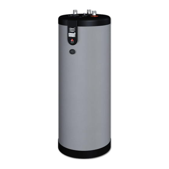
APPLIANCE DESCRIPTION MODELS - SL 320 - 420 - 420 Duplex - 600 Large capacity storage water tanks, to be installed on the floor. Auxiliary connection DHW Domestic hot water outlet 2. Domestic cold water inlet 10. Polypropylene top lid Polyurethane foam insulation 50 mm 11. -
Page 8: Technical Characteristics
TECHNICAL CHARACTERISTICS TECHNICAL CHARACTERISTICS DIMENSIONS AND MAIN CHARACTERISTICS Tank dimensions 420 D 1,602 2,024 2,024 1,901 1,280 1,705 1,705 1,583 Empty weight POSITION The hot water cylinder must be installed in an area that is dry and protected from the elements. Choose the most suitable location according to the position of the boiler and distance to the domestic hot water supply, in order to reduce temperature and pressure drops within the pipe work. - Page 9 TECHNICAL CHARACTERISTICS Main characteristics 420 D Total capacity Primary capacity DHW capacity Primary connection [F] " 1 1/2 1 1/2 1 1/2 DHW connection [M] " 1 1/2 1 1/2 1 1/2 1 1/2 Auxiliary DHW loop connection [M] " 1 1/2 1 1/2 1 1/2...
-
Page 10: Electrical Characteristics
TECHNICAL CHARACTERISTICS ELECTRICAL CHARACTERISTICS Main characteristics 420 D Rated voltage Rated frequency Max. Amp rating Wiring diagram Control thermostat [60/80°C] 2. Load pump [in option] Manual reset high limit thermostat [89°C max.] SL 320 - 420 Y/Gr Y/Gr Blue Y/Gr Y/Gr Black Brown... -
Page 11: Performance
TECHNICAL CHARACTERISTICS PERFORMANCE DHW performance* 420 D Peak flow at 40 °C L/10' 1,195 1,195 1,345 Peak flow at 45 °C L/10' 1,012 1,012 1,153 Peak flow at 60 °C L/10' Peak flow first hour at 40 °C L/60' 2,666 3,151 3,151 3,437... -
Page 12: G3 Requirements And Guidance - Uk Only
TECHNICAL CHARACTERISTICS G3 REQUIREMENTS AND GUIDANCE - UK ONLY Discharge pipe from safety valves The Building Regulation G3 requires that any discharge from an unvented system is conveyed to where it is visible, but will not cause danger to persons in or about the building. The tundish and discharge pipes should be fitted in accordance with the requirements and guid- ance notes of Building Regulation G3. - Page 13 TECHNICAL CHARACTERISTICS Discharge pipe D2 3.56 The discharge pipe (D2) from the tundish should: (a) have a vertical section of pipe at least 300mm long below the tundish before any elbows or bends in the pipework; and (b) be installed with a continuous fall thereafter of at least 1 in 200. 3.57 The discharge pipe (D2) should be made of: (a) metal;...
- Page 14 TECHNICAL CHARACTERISTICS 3.63 The discharge would consist of high temperature water and steam. Asphalt, roofing felt and non-metallic rainwater goods may be damaged by such discharges. temperature relief valve to tundish 600mm maximum Tundish 300mm minimum Discharge below fixed Metal discharge pipe (D2) tundish with grating (3.61 gives continuous fall.
- Page 15 TECHNICAL CHARACTERISTICS Worked example of discharge pipe sizing Figure on the left shows a G1/2 temperature relief valve with a discharge pipe (D2) having 4 No. elbows and length of 7m from the tundish to the point of discharge. From Table: Maximum resistance allowed for a straight length of 22mm copper discharge pipe (D2) from a G1/2 temperature relief valve is 9.0m.
-
Page 16: Installation
INSTALLATION SAFETY INSTRUCTIONS General remarks • Connections (electrical, hydraulic) must be carried out in accordance with applicable standards and regulations. • If the water drawing off point is far from the tank, installing an auxiliary DHW loop can allow to get hot water more quickly at all times. Essential instructions for the correct operation of the system •... - Page 17 The upper hot water layer may then reach very high temperatures. • ACV recommends using a pre-set thermostatic mixing valve in order to provide hot water at a maximum of 60°C. • Water heated to wash clothes, dishes and for other uses can cause serious burns.
-
Page 18: Packing Contents
INSTALLATION PACKING CONTENTS All appliances are delivered, tested and packaged separately. Package • One SL hot water tank. • One multilingual Installation, Operation and Maintenance Instructions. • One energy label TOOLS Smart Line : A1004777 - 661Y3100 • B... -
Page 19: Connection
• Hot water can burn! ACV recommends using a pre-set thermostatic mixing valve in order to provide hot water at a maximum of 60°C. Essential instructions for the correct operation of the system •... - Page 20 INSTALLATION CONNECTION TO THE PRIMARY CIRCUIT (Typical floor installation) Primary circuit filling valve 2. Charging pump 3. Check valve 4. Primary circuit stop valve Expansion vessel 6. Pressure gauge Safety valve 8. Drain valve Stop valve Cold water Hot water Smart Line : A1004777 - 661Y3100 •...
-
Page 21: Parallel Tank Assembly (Typical - 3 Tanks)
INSTALLATION PARALLEL TANK ASSEMBLY (Typical - 3 tanks) Recommended assembly for any waste heat recovery system and for district heating applications. This type of connection reduces the water heating performance of the system. Make sure to oversize the assembly. A specific connection kit is required to build this type of assembly. -
Page 22: Starting Up
STARTING UP STARTING UP SAFETY INSTRUCTIONS TO FILL THE TANK SAFETY INSTRUCTIONS TO FILL THE TANK Essential instructions for the safety of persons and the environment Essential instructions for the safety of persons and the environment • • The DHW tank must always be filled and pressurised before filling and pressurising The DHW tank must always be filled and pressurised before filling and pressurising the primary circuit. -
Page 23: Filling
STARTING UP FILLING Essential instruction for the correct operation of the system • The DHW tank must always be filled and pressurised before filling and pressurising the primary circuit. FILLING THE DHW TANK (Figure 1) Vertical installation on a wall General remark • Connect the safety valve outlet to the sewer. To fill the tank, open a hot water tap (2) located at the highest point of the system. -
Page 24: Checks Before Starting Up
STARTING UP FILLING THE PRIMARY CIRCUIT (Figure 2) General remark • If the tank is used within a heating system, refer to the heating boiler manual. Check that the drain valve (3) of your primary circuit is tightly closed. Open the stop valves (1) and (2) of the primary circuit connected to the heating boiler. Open the air bleed valve (4) located on the top of the hot water tank. -
Page 25: Maintenance
MAINTENANCE PERIODIC CHECKS BY THE USER • Check the pressure of the primary circuit pressure gauge: it should be between 0.5 and 1.5 bar. • Visually inspect, on a regular basis, the valves, connections and accessories in order to detect any leaks or malfunction. -
Page 26: Draining
MAINTENANCE DRAINING Essential instruction for the safety of persons and the environment • The water coming out of the drain valve is very hot and can cause very severe burns. Make sure the area around the hot water flow is clear of people. Essential instruction for the electrical safety •... - Page 27 MAINTENANCE Figure 3 Cold water Hot water Figure 4 Smart Line : A1004777 - 661Y3100 • B...
- Page 28 Smart Line : A1004777 - 661Y3100 • B...
- Page 29 Smart Line : A1004777 - 661Y3100 • B...
- Page 30 Smart Line : A1004777 - 661Y3100 • B...
- Page 31 Smart Line : A1004777 - 661Y3100 • B...
- Page 32 Smart Line : A1004777 - 661Y3100 • B...
Need help?
Do you have a question about the SMART Line 320 and is the answer not in the manual?
Questions and answers