
Related Manuals for Bowflex HVT


Summary of Contents for Bowflex HVT
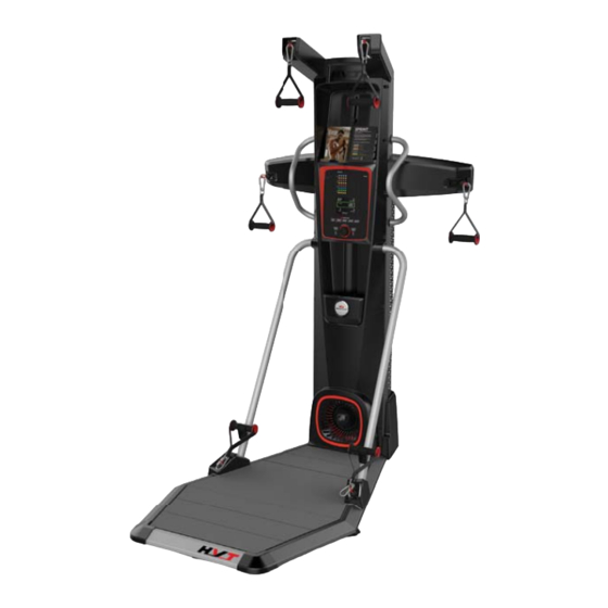
- Page 1 OWNER’S / ASSEMBLY MANUAL OWNER’S / ASSEMBLY MANUAL Manual en Español Latino Americano: www.support.nautilus.com...
-
Page 2: Table Of Contents
Welcome to the Bowflex machine! ™ ® You’re about to experience an incredible workout that can help you lose weight and reshape your entire body so you’ll look and feel better than ever workouts and for tips to keep your machine well maintained. -
Page 3: Important Safety Instructions
Important Safety Instructions When using an electrical appliance, basic precautions should always be followed, including the following: This icon means a potentially hazardous situation which, if not avoided, could result in death or serious injury. Obey the following warnings: Read and understand all Warnings on this machine. for future reference. - Page 4 Before using this equipment, obey the following warnings: Read and understand all Warnings on this machine. If at any time the Warning stickers become loose, unreadable or dislodged, contact Nautilus Customer Service for replacement stickers. To reduce the risk of unsupervised use of the equipment, remove the AC Adapter from the wall outlet and the machine. Place the AC Adapter in a secure location •...
-
Page 5: Safety Warning Labels And Serial Number
Safety Warning Labels and Serial Number WARNING! - Injury or death is possible if caution is not used while using this machine. - Read and follow all warnings on this machine. CAUTION / ATTENTION additional warnings and safety infor- mation. - The heart rate displayed is an for reference only. - Page 6 Specifications / Before Assembly 300 lbs. (136 kg) Assembled Weight: approx. 182 lbs (82.5kg) 83.0” Power Requirements: (210.9 cm) 65.3” Complies with the following: (165.8 cm) 45.2” (114.7 cm) Before Assembly be done in the intended workout location. Basic Assembly Tips •...
-
Page 7: Parts
Parts ( 2 BOXES ) BOX 1 Item Description Item Description 1 - 8 1 each Platform Decking Platform Corner Shroud Platform Frame, Front Middle Shroud, Left Front Hardware Card Handlebar Left Platform Frame Document Kit Quick Start Guide Owner’s Manual... - Page 8 BOX 2 Item Description Item Description Lower Grip Holder Snap Hooks Upper Pulley Shroud, Left Upper Front Shroud Lower Pulley Shroud, Left Owner’s Manual...
- Page 9 Hardware / Tools / Assembly Item Description Item Description Note: after the proper assembly of your machine. Tools Included Not Included (recommended) Owner’s Manual...
- Page 10 Assembly 1. Safely Remove the Frame Assembly from the Shipping Box and Stand Upright in the Intended Workout Area. Remove the Upper Shroud from Frame Assembly. Note: assembly. involving these parts. Do not do steps that involve heavy lifting or awkward movements on your own. Owner’s Manual...
- Page 11 2. Safely Remove the Right Shipping Support and Attach the Right Platform Frame to the Frame Assembly Note: Owner’s Manual...
- Page 12 3. Safely Remove the Left Shipping Support and Attach the Left Platform Frame to the Frame Assembly Note: Owner’s Manual...
- Page 13 4. Flip the Front Platform Frame and Attach the Platform Corner Shrouds Owner’s Manual...
- Page 14 5. Attach Front Platform Frame Assembly to Platform Frames Note: Owner’s Manual...
- Page 15 6. Release the Lower Ropes from the Snap Hooks and Route through the Platform Frames Owner’s Manual...
- Page 16 7. Pivot, Connect, and Place the Platform Decking into the Platform Frame Assembly Note: a ‘v’ in the Platform Frame. With your foot centered on the piece marked ‘2’, push downward to set into place. Owner’s Manual...
- Page 17 8. Route the Lower Rope and Attach the Support Arms and Securing Ball Note: pull out of the round opening. Owner’s Manual...
- Page 18 9. Tighten All Hardware from Previous Steps 10. Disconnect the Ropes and Route the Front Rope (*) through Upper Pulley Arms and Insert to Frame Assembly Note: the round opening. Owner’s Manual...
- Page 19 11. Attach the Middle Pulley Arms and Route the Middle Ropes Note: the end of the rope after routing. Start the rope through the oval opening of the securing ball, and pull out of the round opening. Owner’s Manual...
- Page 20 12. Attach Upper Pulley Shrouds to Upper Pulley Arms Note: Owner’s Manual...
- Page 21 13. Attach the Handlebars to the Frame Assembly Owner’s Manual...
- Page 22 14. Attach Upper Rear Shroud to Frame Assembly Owner’s Manual...
- Page 23 15. Attach the Middle Pulley Shrouds to the Frame Assembly Note: Owner’s Manual...
- Page 24 16. Attach Upper Shroud to Frame Assembly Note: Do not install hardware in the lower openings. Do not fully tighten hardware until instructed. Owner’s Manual...
- Page 25 17. Connect the Cables and Attach the Console Assembly to Frame Assembly Note: Owner’s Manual...
- Page 26 18. Attach Lower Pulley Shrouds to Frame Assembly Owner’s Manual...
- Page 27 19. Attach Lower Grip Holders to Frame Assembly Owner’s Manual...
- Page 28 20. Connect the Power Input Cables and Attach the Lower Rear Shroud to Frame Assembly Note: Owner’s Manual...
- Page 29 21. Carefully Attach Hand Grips to Ropes Note: Owner’s Manual...
- Page 30 22. Secure the Training Guide to the Media Tray on the Upper Shroud Note: Owner’s Manual...
- Page 31 23. Attach Power Adapter to Frame Assembly Note: Do not crimp the Cables. 24. Using the Hand Grips, Fully Extend each of the Ropes and Remove any Twists from Them Note: ® gradually allowing them to retract. ropes are fully retracted. The rope will be under tension and will retract itself into the damage to the machine or injury to the user or bystanders.
-
Page 32: Storing Your Machine
25. Final Inspection excess hardware according to your local regulations. Moving and Storing the Machine Do not move the machine without aid. Injury to you or damage to the machine can occur. Leveling the Machine 1. Place the machine in your workout area. Do not adjust the levelers to such a height that they detach or unscrew from the machine. -
Page 33: Features
Features Upper Pulley Static Handlebars Middle Pulley Console Hand Grip Holder Power Inlet Hand Grip Lower Pulley Leveler Platform Owner’s Manual... - Page 34 Pulleys ® Platform Note: If necessary, grab onto the Static Handlebars for stability. Console Features icon ® Exercise segment Bluetooth icon ® enabled device is connected to the Console. ® ® Round display Note: Owner’s Manual...
- Page 35 Exercise segment that Workout Program. Total Time display Total Calories display Active Exercise Segment Timers: Work display Rest display Break display Total Power display Resistance display Heart Rate (if supplied) of breath, or feel faint. Contact your doctor before you use the machine again. The heart rate displayed on the console is an Owner’s Manual...
- Page 36 Keypad Functions User button Active User display Note: For a more accurate calorie count, be sure to edit your Workout Program buttons START button Resistance Level dial increase a value, counter-clockwise will decrease a value. PAUSE/STOP button Pauses an active workout, ends a paused workout, or goes back to the previous screen. Add Time button Note: Volume button and indicator lights...
- Page 37 Media Shelf. Connectivity on your fitness machine ® ® icon will activate. If ® The “Bowflex HVT™” Software App ® ® score, resistance, and heart rate (if supplied). Plus, it automatically posts your workout data to MyFitnessPal ® ® ®...
- Page 38 you maintain your target heart rate, the more fat your body will burn. Fat-Burning Target Heart Rate higher or lower. Consult your physician for your individual target heart rate zone. Note: Owner’s Manual...
-
Page 39: Operations
Operations How Often Should You Exercise for reference only. • 3 times a week for about 20 minutes each day. • Schedule workouts in advance and try to follow the schedule. Note: If you are new to exercise (or returning to a regular exercise program), and you are unable to comfortably complete 20 minutes of con- tinuous exercise at one time, select a few workouts and do them for 5 –... -
Page 40: Getting Started
Getting Started ® required clearance includes the full extent of your reach above your head. Place the machine on a clean, hard, level surface, free from unwanted material or other objects that may hamper your ability to machine. objects into an opening of the machine. Carefully mount the platform. -
Page 41: Power Up Mode
Note: fully retract into the machine. Power-Up Mode ( Start-Up screen ) Auto Shut-Off (Sleep Mode) display is off while in Sleep Mode. Note: Push and hold the User button for 3 seconds to begin the Edit User mode. Note: adjust the resistance to the ending resistance level the last time that exercise was done. - Page 42 ROUND 1. Speed squat 2. Chest press 3. Squat jump program. 6. Split leg alternating bicep curl SPRINT program 8. Squat with overhead press Each exercise is performed for 20 seconds (Work) followed by 10 ROUND CIRCUIT program 4. Split jump 5.
- Page 43 ROUND BUILDER program 1. Speed squat 7. Combo tricep extension bicep curl an additional exercise. 8. Forward lunge chest press Each exercise is performed for 30 seconds (Work). ROUND MANUAL program total time that the fan is moving. When the resistance fan stops, the time count pauses, while the total time of the workout continues.
- Page 44 Carefully step up onto the platform. Grasp the appropriate Handle (Upper, Middle, or Lower Handles) and begin the first exercise of the Workout Program after the 3-2-1 countdown. requires it. segment or another Work segment. Do not release the Hand Grips until the Hand Grip Stops are at rest and the ropes are fully retracted. Releasing the Hand Grips when not at rest may cause damage to the machine or injury to the user or bystanders.
- Page 45 Note: Changing Resistance Levels that exercise segment. Note: contact our Customer Service department for assistance. Total Power score ® ® Note: your previous scores and not to other User Profiles. Owner’s Manual...
-
Page 46: Machine Settings Mode
Machine Settings Mode Mode. Note: Note: ® Note: Owner’s Manual... -
Page 47: Maintenance
Maintenance done. Worn or damaged components must be repaired or replaced immediately. Only manufacturer supplied components can be used to maintain and repair the equipment. If at any time the Warning labels become loose, unreadable or dislodged, contact Nautilus Customer Service for re-placement labels. - Page 48 Maintenance Parts Owner’s Manual...
- Page 49 Platform Decking Upper Pulley Shroud, Left Platform Corner Shrouds Upper Front Shroud Front Platform Frame lower Grip Holder Left Platform Frame Middle Shroud, Left Front Lower Pulley Shroud, Left Snap Clip Servo Motor Fan Shroud Elastic Cord Handlebar Owner’s Manual...
- Page 50 Troubleshooting Things to Check Solution Outlet Power cord not plugged in Check console display for Check for visual sign that console display is cracked or otherwise damaged. damage Console display Console. If problem persists Contact Customer Service. Chest Strap (optional) ”...
- Page 51 Owner’s Manual...
- Page 52 Owner’s Manual...
- Page 53 Owner’s Manual...
- Page 54 Buy Back Guarantee ® ® price, less shipping and handling. ® apply to sales made by dealers or distributors. ® ® Your Name Your Phone Number in each box of merchandise. ® recommends that you obtain tracking numbers and insure your shipment. Owner’s Manual...
-
Page 55: Warranty
Warranty Who Is Covered This warranty is valid only to the original purchaser and is not transferable or applicable to any other person(s). What Is Covered Nautilus, Inc. warrants that this product is free from defects in materials and workmanship, when used for the purpose intended, under normal conditions, and provided it receives proper care and maintenance as described in the Product’s Assembly and Owner’s manual. - Page 56 8016644.061518.C...
Need help?
Do you have a question about the HVT and is the answer not in the manual?
Questions and answers