Bowflex HVT Owner's Manual
Hide thumbs
Also See for HVT:
- User manual ,
- Service manual (163 pages) ,
- Owner's/assembly manual (56 pages)
Table of Contents
Advertisement
Advertisement
Table of Contents

Related Manuals for Bowflex HVT


Summary of Contents for Bowflex HVT
- Page 1 O WN E R’S / A SSE MBLY MA N UA L O WN E R’S / A SSE MBLY MA N UA L...
-
Page 2: Table Of Contents
Nautilus, Inc. | ® indicates trademarks registered in the United States. These marks may be registered in other nations or otherwise protected by common law. Bowflex, the Bowflex logo, Bowflex Trainer, HVT, Nautilus, Schwinn, and Universal are trademarks owned by or licensed to Nautilus, Inc. -
Page 3: Important Safety Instructions
Important Safety Instructions When using an electrical appliance, basic precautions should always be followed, including the following: This icon means a potentially hazardous situation which, if not avoided, could result in death or serious injury. Obey the following warnings: Read and understand all Warnings on this machine. Carefully read and understand the Assembly/Owner’s Manual. - Page 4 Before using this equipment, obey the following warnings: Read and understand the complete Manual. Keep the Manual for future reference. Read and understand all Warnings on this machine. If at any time the Warning stickers become loose, unreadable or dislodged, contact your local distributor for replacement stickers.
-
Page 5: Safety Warning Labels And Serial Number
Safety Warning Labels and Serial Number CAUTION - Stay in safe workout area. - Keep at least one foot on the platform during a workout. - Failure to do so could lead to equipment instability. CAUTION / ATTENTION Power Inlet Product Specification Serial Number Owner’s Manual... -
Page 6: Specifications / Before Assembly
™ rubber machine mat provides a non-slip, rubber surface which limits static discharge and reduces the possibility of display or running errors. If pos- sible, put your Bowflex Machine Mat in your selected workout area before you begin assembly. ®... -
Page 7: Parts
Parts ( 2 BOXES ) BOX 1 Item Description Item Description 1 - 8 1 each Platform Decking Upper Pulley Arm, Left Platform Corner Shroud Middle Pulley Arm, Left Platform Frame, Front Middle Shroud, Left Back Right Platform Frame Middle Shroud, Left Front Support Arm, Right Hardware Card AC Power Adapter... - Page 8 BOX 2 Item Description Item Description Lower Grip Holder Snap Hooks Upper Pulley Shroud, Left Upper Pulley Shroud, Right Upper Front Shroud Hand Grip, 1-D Ring Lower Pulley Shroud, Left Hand Grip, 2-D Ring Console Assembly Rear Shroud, Lower Frame Assembly Lower Pulley Shroud, Right Owner’s Manual...
-
Page 9: Hardware / Tools
Hardware / Tools / Assembly Item Description Item Description Socket Hex Head Screw, M8x1.25x20 Black Flat Washer, M8x18 Black Lock Washer, M8x14.8 Black Truss Phillips Head Screw, M5x16 Black Phillips Head Screw, M4.2x16 Black Securing Ball Note: Select pieces of Hardware have been provided as spares on the Hardware Card. Be aware that there may be remaining Hardware after the proper assembly of your machine. -
Page 10: Assembly
Assembly 1. Safely Remove the Frame Assembly from the Shipping Box and Stand Upright in the Intended Workout Area. Remove the Upper Shroud from Frame Assembly. Note: Do not disconnect the indicated ropes and snap rings until instructed. Remove all the packaging from the parts to assist with assembly. - Page 11 2. Safely Remove the Right Shipping Support and Attach the Right Platform Frame to the Frame Assembly Note: Only finger-tighten the hardware until instructed to fully tighten. Be sure not to pinch the ropes during assembly. Owner’s Manual...
- Page 12 3. Safely Remove the Left Shipping Support and Attach the Left Platform Frame to the Frame Assembly Note: Only finger-tighten the hardware until instructed to fully tighten. The Shipping Supports and attached hardware are not used on the final assembly, and should be disposed of according to your local regulations. Owner’s Manual...
- Page 13 4. Flip the Front Platform Frame and Attach the Platform Corner Shrouds Owner’s Manual...
- Page 14 5. Attach Front Platform Frame Assembly to Platform Frames Note: To assist with assembly, pivot the Front Platform Frame Assembly upward slightly until holes are aligned and install hardware. Owner’s Manual...
- Page 15 6. Release the Lower Ropes from the Snap Hooks and Route through the Platform Frames Owner’s Manual...
- Page 16 7. Pivot, Connect, and Place the Platform Decking into the Platform Frame Assembly Note: Start with the piece marked “8” and work toward the Frame Assembly. With the initial piece pivoted up and toward the Frame Assembly, insert the tab of the next piece and pivot the initial piece downward. With the last two pieces (marked “1” and “2”), place them so they form a ‘v’...
- Page 17 8. Route the Lower Rope and Attach the Support Arms and Securing Ball Note: Route Lower Rope through the Support Arm. Then attach the upper hardware first ( * ). Only finger-tighten the hardware until instructed to fully tighten. Attach Securing Ball to Rope and remove the routing wire. Start the rope through the oval opening of the securing ball, and pull out of the round opening.
-
Page 18: Frame Assembly
9. Tighten All Hardware from Previous Steps 10. Disconnect the Ropes and Route the Front Rope (*) through Upper Pulley Arms and Insert to Frame Assembly Note: Attach a securing ball to the end of the rope after routing. Start the rope through the oval opening of the securing ball, and pull out of the round opening. - Page 19 11. Attach the Middle Pulley Arms and Route the Middle Ropes Note: The parts have a right (“ R ”) and left (“ L ”) mark to assist with assembly. If necessary, push the Upper Pulley Arms toward the back to align the side hardware openings.
- Page 20 12. Attach Upper Pulley Shrouds to Upper Pulley Arms Note: Be sure the tab on the Upper Pulley Shroud is behind the securing ball cage. Fully tighten this hardware and future hardware unless specifically instructed not to tighten. Owner’s Manual...
- Page 21 13. Attach the Handlebars to the Frame Assembly Owner’s Manual...
- Page 22 14. Attach Upper Rear Shroud to Frame Assembly Owner’s Manual...
- Page 23 15. Attach the Middle Pulley Shrouds to the Frame Assembly Note: The parts have a right (“ R ”) and left (“ L ”) mark to assist with assembly. Snap the Rear Shrouds onto the Middle Pulley Assemblies first (*). Owner’s Manual...
- Page 24 16. Attach Upper Shroud to Frame Assembly Note: Do not install hardware in the lower openings. Do not fully tighten hardware until instructed. Owner’s Manual...
- Page 25 17. Connect the Cables and Attach the Console Assembly to Frame Assembly Note: Do not crimp the Cables. Tighten all hardware from previous steps. Owner’s Manual...
- Page 26 18. Attach Lower Pulley Shrouds to Frame Assembly Owner’s Manual...
- Page 27 19. Attach Lower Grip Holders to Frame Assembly Owner’s Manual...
- Page 28 20. Connect the Power Input Cables and Attach the Lower Rear Shroud to Frame Assembly Note: Be sure to remove any shipping cardboard before attaching the Rear Shroud. Do not crimp the Cables. Owner’s Manual...
- Page 29 21. Carefully Attach Hand Grips to Ropes Note: Be sure to keep your hands away from the snap hooks when attaching the Hand Grips. Owner’s Manual...
- Page 30 22. Secure the Training Guide to the Media Tray on the Upper Shroud Note: Insert the Pointed Tabs into the spiral binding of the Training Guide. The Securing Clasp can be adjusted and rotated as necessary. When placed properly, the Training Guide should be easily opened and the pages easily turned. Owner’s Manual...
- Page 31 Twists from Them Note: The Ropes on the Bowflex HVT machine may have become twisted during shipment or ® assembly. Fully pull out each Rope, one at a time, and examine it. Remove any twists in the Ropes while gradu- ally allowing them to retract.
-
Page 32: Storing Your Machine
25. Final Inspection Inspect your machine to ensure that all hardware is tight and components are properly assembled. Recycle or discard the Shipping Supports and excess hardware according to your local regulations. Be sure to record the serial number in the field provided at the front of this manual. Do not use until the machine has been fully assembled and inspected for correct performance in accordance with the Owner’s Manual. -
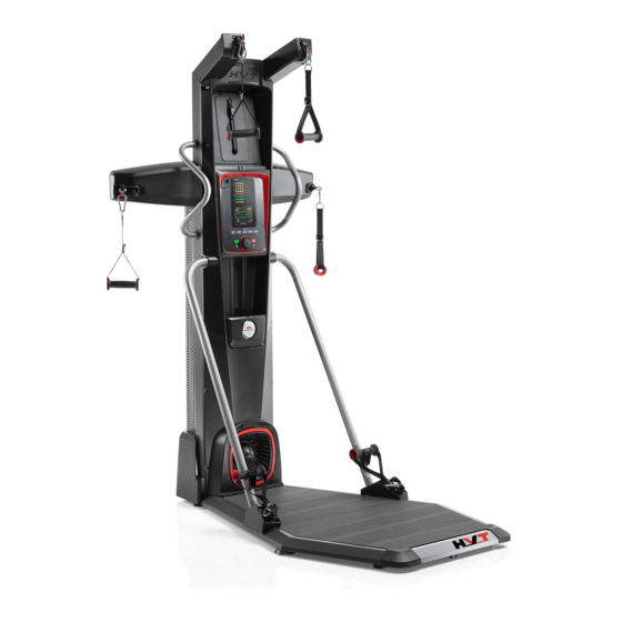
Page 33: Features
Features Upper Pulley Media Shelf / Accessory Storage Area Static Handlebars Training Guide Middle Pulley Resistance Level Dial Console Water Bottle Holder Resistance Engine Hand Grip Holder Resistance Fan Power Inlet Hand Grip Lower Pulley Leveler Platform Use the values calculated or measured by the machine’s computer for reference purposes only. The heart rate displayed is an approximation and should be used for reference only. - Page 34 Pulleys The Bowflex HVT™ machine has three different pulley positions: Upper, Middle and Lower. Each exercise uses the hands grips attached to the ® specific pulleys to affect the intended muscle group. Platform The Platform is a slightly raised stage defining the workout area. Most of the exercises involve the user being fully on the Platform. If required to perform an exercise, the user can step off the platform with one foot but must stay within the Workout area.
- Page 35 Exercise segment Each segment on the Console is a specific exercise for the Workout Program. Exercise segments with matching colors are the same exercise for that Workout Program. Total Time display The Total Time display shows the length of time for the selected Workout Program. The maximum time is 99:59 minutes. Total Calories display The Total Calories display shows the estimated calories that have been burned during a workout.
- Page 36 The Volume button sets the sound level of the Console, and the indicator lights show the current setting; low (1 LED), medium (2 LEDs), high (3 LEDs), or off (no LEDs). Training Guide The Training Guide coaches the user through the three core Workout Programs, and contains all the exercises available with the Bowflex HVT™ ®...
-
Page 37: Connectivity On Your Fitness Machine
® The “Bowflex HVT™” App connects with your fitness machine to provide the sequence of exercises that make each of the workout programs. Each ® exercise is presented with hints, descriptions, and video demonstrations. The App tracks the total time, calories burned, power score, resistance, and heart rate (if supplied). - Page 38 The Heart Rate table is an estimate of what Heart Rate Zone (HRZ) is effective to burn fat and improve your cardiovascular system. Physical condi- tions vary, therefore your individual HRZ could be several beats higher or lower than what is shown. The most efficient procedure to burn fat during exercise is to start at a slow pace and gradually increase your intensity until your heart rate reaches between 60 –...
-
Page 39: Operations
This form of workout allows you to burn more calories than a standard workout in a shorter period of time. The Bowflex HVT™ machine combines “Work” and “Rest” segments to create an Interval workout. During a “Work” segment, push yourself to a ®... -
Page 40: Getting Started
Getting Started Place the Bowflex HVT™ machine in your workout area. Be sure there is an adequate height clearance to safely perform the exercises. This ® required clearance includes the full extent of your reach above your head. Place the machine on a clean, hard, level surface, free from unwanted material or other objects that may hamper your ability to move freely. -
Page 41: Power Up Mode
Workout Programs The Bowflex HVT™ machine has four Workout Programs; SPRINT, CIRCUIT, BUILDER, and MANUAL. Each Workout Program guides the user ® through a unique sequence of exercises, quantity of Rounds, and times for each workout segment (Work, Rest, and Break). - Page 42 ROUND ROUND ROUND ROUND 1. Speed squat The Software App follows along with the Console, showing 2. Chest press the exercise and all the workout information to perform it. The 3. Squat jump Software App automatically shifts to the next exercise in the 4.
-
Page 43: Manual Program
All exercises in this manual are based on the calibrated resistance and capacity levels of this machine. Only exercises included in this manual or in materials authorized and supplied by Bowflex are recommended for operation with this machine. Circuit Builder... -
Page 44: Paused/Results
To start a Workout Program: Carefully step up onto the platform. Place the Training Guide on the Media Shelf opened to the first exercise of the Workout Program, or your synced smart device with the Soft- ware App open. Push the desired Workout Program; SPRINT, CIRCUIT, BUILDER, or MANUAL. Push the START button to begin the selected Workout Program. -
Page 45: Change Resistance Levels
The resistance settings supplied by the resistance fan can vary based on environmental and usage patterns and other factors. Supplied resistance may degrade over time and after extensive usage. Total Power score The Total Power score is a unit-less point system that that dynamically represents a User’s performance on the Bowflex HVT™ machine. The Total ®... -
Page 46: Machine Settings Mode
Machine Settings Mode The Machine Settings Mode lets you view maintenance statistics (Total Hours and Software Version) or fully reset the Console. Push and hold down the ADD TIME and PAUSE/STOP buttons for 3 seconds while in the Power-Up Mode to go into the Machine Settings Mode. -
Page 47: Maintenance
Maintenance Read all maintenance instructions fully before you start any repair work. In some conditions, an assistant is required to do the necessary tasks. Equipment must be regularly examined for damage and repairs. The owner is responsible to make sure that regular maintenance is done. - Page 48 Maintenance Parts Owner’s Manual...
- Page 49 Middle Pulley Arm, Left Middle Shroud, Right Back Platform Decking Upper Pulley Shroud, Left Middle Shroud, Right Front Platform Corner Shrouds Upper Front Shroud Hand Grip, 1-D Ring Front Platform Frame Upper Pulley Arm, Left lower Grip Holder Left Platform Frame Upper Pulley Arm, Right Lower Pulley Shroud, Right Middle Shroud, Left Front...
-
Page 50: Troubleshooting
Troubleshooting Condition/Problem Things to Check Solution Unit will not power up/turn on/start Outlet Make sure outlet is functioning correctly. Verify this by plugging another device (ex: lamp) into the outlet. If outlet is connected to a light switch, check to make sure it is on. If outlet is not functioning find a working outlet. Power cord not plugged in Make sure the power cord is firmly secured to A/C inlet on the machine and firmly inserted into a non-GFI/AFCI wall socket. - Page 51 Owner’s Manual...
- Page 52 8016934.010118.B...
Need help?
Do you have a question about the HVT and is the answer not in the manual?
Questions and answers