Table of Contents
Advertisement
Quick Links
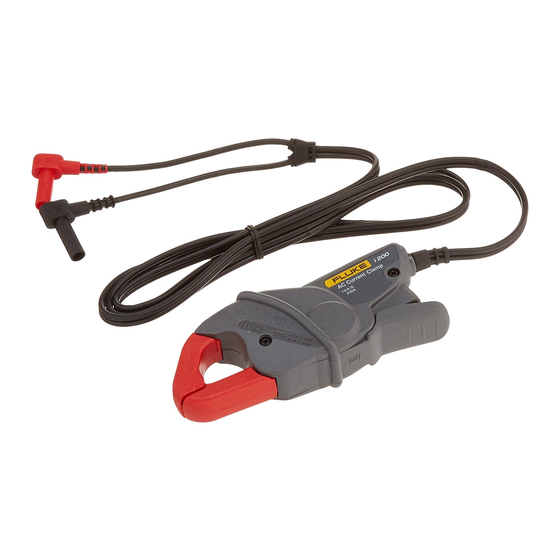
i200/i200s
AC Current Clamp
Instruction Sheet
Introducing the i200/i200s
The i200 is a single range 200A clamp-on AC Current Clamp with
current output via safety shrouded banana plugs.
The i200s is a dual range 20A and 200A clamp-on AC Current
Clamp with voltage output via a safety insulated BNC connector.
A dual banana to BNC adapter is supplied to allow the i200s to be
connected to multimeters with banana input.
Unpacking
The following items should be included in your Current Clamp box:
•
Current Clamp
•
Dual Banana to BNC Adapter model PM9081 (only with i200s)
•
Instruction Sheet (this paper)
Check the contents of the shipping box for completeness. If
something in the box has been damaged or missing, contact your
distributor or the nearest FLUKE sales or service office immediately.
Safety Information
Read First: Safety Information.
To ensure safe operation and service of the
current clamp, follow these instructions:
•
Read the operating instructions before use and follow all safety
instructions.
•
Use the Current Clamp only as specified in the operating
instructions, otherwise the clamp's safety features may not
protect you.
•
Adhere to local and national safety codes. Individual protective
equipment must be used to prevent shock and arc blast injury
where hazardous live conductors are exposed.
•
Do not hold the Current Clamp anywhere beyond the tactile
barrier, see Figure 1.
•
Before each use, inspect the Current Clamp. Look for cracks or
missing portions of the clamp housing or output cable
insulation. Also look for loose or weakened components. Pay
particular attention to the insulation surrounding the jaws.
•
Check the magnetic mating surfaces of the clamp jaws; these
should be free of dust, dirt, rust and other foreign matter.
•
Never use the clamp on a circuit with voltages higher than 600
V CAT III.
−
CAT III equipment is designed to protect against transients
in equipment in fixed equipment installations, such as
distribution panels, feeders and short branch circuits, and
lighting systems in large buildings.
•
Use extreme caution when working around bare conductors or
bus bars. Contact with the conductor could result in electric
shock.
4822 872 00934
July 1998, Rev. 5, 08/05
© 1998 - 2005 Fluke Corporation.
All rights reserved.
Printed in France
All product names are trademarks of
their respective companies.
•
Use caution when working with voltages above 60 V dc, 30 V ac
rms or 42 V ac peak. Such voltages pose a shock hazard.
®
Tactile barrier
Figure 1. Safely holding the Current Clamp
Symbols
May be used on HAZARDOUS LIVE
conductors.
Product is protected by double insulation.
Risk of Danger. Important information. See
Instruction Sheet.
Risk of Electric Shock.
Conforms to relevant European standards.
Earth ground.
Specifications
SAFETY
Input jaws & output floating
Complies with American
voltage to ground
industry standards
UL61010B-1 & UL61010B-2-
032 and European standards
EN/IEC 61010-1 2nd Edition
& EN/IEC 61010-02-032 for
600V CAT III, pollution
degree 2.
EMC
Complies with standards
EN/IEC 50081-1 &
EN/IEC 50082-2
ELECTRICAL SPECIFICATIONS
All Electrical Specifications are valid at the following reference
conditions:
•
Ambient temperature
23±3°C (73±3°F)
•
Relative Humidity
20 to 75%
•
Frequency
48 to 65 Hz
•
Continuous external field
< 40 A/m
•
Ω
Ω
Load impedance
i200: 0.2
...15
Ω
i200s: >1 M
// 100 pF
•
The current may not contain any DC component
•
No influence from adjacent currents
•
The conductor must be centered within the jaw aperture
20A Range (i200s only)
Measuring range
0.1 to 24A
Maximum current
24A
Crest factor *
< 3
Maximum non-destructive
200A (Frequency ≤ 1 kHz and
current
crest factor < 3)
Output signal
100 mV/A
Output impedance
≤ 20 Ω @ 1 kHz
Basic accuracy
48 Hz to 65 Hz
≤ 2% + 0.5A
Additional error:
40 Hz to 48 Hz and
+ < 10%
65 Hz to 1 kHz
1 kHz to 10 kHz
+ < 15%
Phase shift
Unspecified
200A Range
i200
i200s
Measuring range
0.5 to 240A
0.5 to 240A
Maximum current
240A
240A
Crest factor *
< 3
< 3
@ Frequency ≤ 1 kHz and
Maximum non-destructive
crest factor < 3
current
Continuous
200A
10 min ON
240A
/30 min OFF
Output signal
1 mA/A
10 mV/A
Output impedance
-
≤ 10 Ω @ 1 kHz
Basic accuracy
48 Hz to 65 Hz
0.5A to 10A
≤ 3% + 0.5A
≤ 3.5% + 0.5A
10A to 40A
≤ 2.5% + 0.5A
≤ 3% + 0.5A
40A to 100A
≤ 2% + 0.5A
≤ 2.5% + 0.5A
100A to 240A
≤ 1% + 0.5A
≤ 1.5% + 0.5A
Additional error:
40 Hz to 48 Hz and
+ < 3%
+ < 3%
65 Hz to 1 kHz
1 kHz to 10 kHz
+ < 12%
+ < 12%
Phase shift
0.5A to 10A
Unspecified
Unspecified
10A to 40A
≤ 5 °
≤ 6 °
40A to 100A
≤ 3 °
≤ 4 °
100A to 240A
≤ 2.5 °
≤ 3 °
All ranges
i200
i200s
Load on output
0.2...15 Ω
>1 MΩ // < 100 pF
Load Influence
Current: < 1%
-
Phase: < 1°
-
Bandwidth
-1.5 dB
40 Hz to 10 kHz
40 Hz to 10 kHz
-3dB
40 kHz
40 kHz
Additional errors
With temperature
≤ 0.15 % / 10 K
With position of
≤ 0.5 % @ 50 Hz
conductor in the
clamp aperture
With adjacent
≤ 15 mA / A @ 50 Hz
conductors
*
This is the maximum permissible ratio between the peak value
of a superimposed transient and the ac rms value.
GENERAL
Clamp Dimensions
135 x 50 x 30 mm
(5.3 x 2 x 1.2 in)
Protection index
IP40
Jaw Opening
21 mm (0.82 in)
Height of open Jaws
69 mm (2.7 in)
Maximum conductor size
∅ 20 mm (0.8 in) or
busbar 20 x 5 mm (0.8 x 0.2 in)
Weight
180 g (6.4 oz)
Cable length
i200
1.5 m (59 in)
i200s
2m (79 in)
Temperature
Operating
-10 to +55°C (+14 to +131°F)
Non-operating
-40 to + 70°C (-40 to +158°F)
Relative Humidity
Operating
85%, up to +30°C (+86°F)
75%, up to +55°C (+131°F)
Altitude
Operating
to 2000 m (6500 ft)
Non-operating
to 12000 m (40000 ft)
EMC
EN/IEC 50081-1
EN/IEC 50082-2 (3V/m,
2.74V/yd)
Instrument Compatibility
The i200s is compatible with any Fluke ScopeMeter test tool, Power
Harmonics Analyzer, Oscilloscope, Multimeter, or other voltage
measurement device that has the following features:
•
BNC input connector. The Dual Banana to BNC Adapter
included in the package, can be used to connect to standard
inputs on multimeters. For the 120 series ScopeMeters, use
the BB120 Shielded Banana to BNC Adapter.
•
Input accuracy of 2% or better to take full advantage of the
accuracy of the Current Clamp.
•
Input impedance of greater than or equal to 1 MΩ, and for full
bandwidth and accuracy, a maximum input capacity of 100 pF.
•
A pass- band of more than four times the frequency of the
waveform to be measured.
The i200 is compatible with any Fluke Multimeter or any other
current measurement device that has the following features:
•
Banana inputs.
•
Input accuracy of 2% or better to take full advantage of the
accuracy of the Current Clamp.
•
Input impedance of 0.2Ω ...15Ω
•
A pass-band of more than four times the frequency of the
waveform to be measured.
Advertisement
Table of Contents

Related Manuals for Fluke i200


Summary of Contents for Fluke i200
-
Page 1: Safety Information
Introducing the i200/i200s Maximum current This is the maximum permissible ratio between the peak value The i200 is a single range 200A clamp-on AC Current Clamp with Crest factor * < 3 of a superimposed transient and the ac rms value. -
Page 2: Measurement Considerations
LIMITED WARRANTY & LIMITATION OF LIABILITY Using the Current Clamp Measurement Considerations This Fluke product will be free from defects in material and To use the Current Clamp, follow these instructions: Observe the following guidelines for positioning the Current Clamp workmanship for one year from the date of purchase.
Need help?
Do you have a question about the i200 and is the answer not in the manual?
Questions and answers