Table of Contents
Advertisement
Quick Links
Advertisement
Chapters
Table of Contents

Related Manuals for Tadano GR-700N


Summary of Contents for Tadano GR-700N
- Page 2 Foreword Foreword This service manual describes the composition of the Model GR-700N-1 rough terrain crane, its adjustment methods and hydraulic and electric circuit diagrams. This service manual applies to the cranes with the specification numbers given below. Check the specification number on the nameplate of your crane.
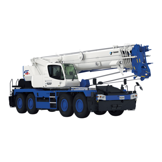
- Page 3 Foreword 2. External view The following is the traveling posture. Front, rear, right, and left are the directions viewed from a position when operator sits on operator's seat with the boom directed to the front of the frame. Those directions remain invariant regardless of slewing direction of the superstructure.
- Page 4 Foreword 3. Outline of specifications Spec. No. Item GR-700N-1 GR-700N-1 GR-700N-1 -00101 -00121 -00122 No. of boom sections No. of jib stages Single top Fitted Main winch Fitted Auxiliary winch Fitted Winch Winch high-speed hoisting down Fitted Winch brake Automatic brake (Neutral brake)
- Page 5 Foreword 4. Conversion table Length millimeter centimeter meter inch foot mile kilometer in, ” ft, ’ 1×10 1×10 3.93701×10 3.28084×10 1.60934 1×10 1×10 3.93701×10 3.28084×10 6.21373×10 1×10 1×10 3.93701×10 3.28084 2.54×10 2.54 2.54×10 8.33333×10 3.048×10 3.048×10 3.048×10 1.2×10 Speed km/h mile/h, mph 6.21373×10 1.60934...
- Page 6 Foreword Mass gram kilogram ounce pound metric ton short ton s. t 1×10 3.5274×10 2.20462×10 1×10 1.10231×10 1×10 3.5274×10 2.20462 1×10 1.10231×10 2.83495×10 2.8349×10 6.25×10 2.83495×10 3.12494×10 4.53592×10 4.53592×10 1.6×10 4.53592×10 5×10 1×10 1×10 3.5274×10 2.20462×10 1.10231 9.07185×10 9.07185×10 3.2×10 2×10 9.07185×10 Pressure...
- Page 7 Foreword 5. Drawing method of illustrations in this service manual The third angle projection method of mechanical drawing is used for the illustrations in this service manual. The third angle projection method is generally composed of the front view (the figure viewed from the front: A), top view (the figure viewed from the top: B), and right-side view (the figure viewed from the right: C) as shown below.
- Page 8 6. Group index Data, Adjustment and Checks System Diagrams WA04-4651E...
- Page 9 Foreword 7. Contents Spec. No. Section GR-700N-1 GR-700N-1 GR-700N-1 -00101 -00121 -00122 Data, Adjustment and Checks Service Data Hydraulic Pressure Adjusting pressure Pneumatic Pressure Air Bleeding Procedure Electric Adjusting procedure Crane Operation Assembly Adjustment Traveling Device Crane Operation Operation Check...
-
Page 10: Table Of Contents
Data, Adjustment and Checks Contents Y-1 Service Data ........1 Y-2 Adjusting Pressure (Hydraulic Pressure) ....14 Amounts of oil and coolant ......1 Location (position of relief valve etc.) ..14 Operating speed ........1 Items ............ 15 Hydraulic device ........2 Winch ............ - Page 11 Y-4 Air Bleeding Procedure ....25 Y-5 Adjusting Procedure (Electric) ..34 Hydraulic pump ........25 Switch adjustment procedure ....34 Steering and ACC charging pump Over-front detection switch (CN521) ..34 (double gear pump) ......25 Boom full retraction detection switch Main pump ..........
- Page 12 Boom clearance adjustment ....48 Parking brake adjustment ......63 Shim adjustment at lower oblique sides Adjusting the clearance of the boom bottom ......49 (between brake shoe and drum) ..63 Shim adjustment at upper part Connecting parking brake of the boom bottom ......
- Page 13 Y-8 Operation Check Y-9 Operation Check (Crane Operation) ....72 (Traveling Device) ....77 Outrigger status indicator Permanent-magnetic retarder ....77 by operating outrigger inside cab . 72 Automatic transmission ......78 Outrigger status indicator Rear steering lock ........79 by lower outrigger control box ..
-
Page 14: Service Data
Service Data Service Data [NOTICE] Standard values are values at time of vehicle shipment from TADANO. Limit values are the limits at which adjustment or part replacement is necessary. 1. Amounts of oil and coolant (1L = 2.64172 × 10... -
Page 15: Hydraulic Device
Service Data 3. Hydraulic device 3.1 Hydraulic pump Item Standard value Remarks Speed reducing ratio 0.642 Idling (min 1090 ± 31 Eng.700 ± 20 min (PTO-ON) Crane pump (double piston pump) 2414 Max. (min Eng.1550 (PTO-ON) Displacement (cm /rev) 82 + 82 Speed reducing ratio 0.815 Idling (min... -
Page 16: Hydraulic Cylinder
Service Data 3.3 Hydraulic cylinder (1 m = 3.28084 ft) (1 mm = 3.93701 × 10 Remarks Standard Item value Condition and method Safety and notice Inspection conditions 1. Boom angle: 60°±2° (Lowering operation) 2. Boom full retraction 3. Engine stop 1°... - Page 17 Service Data Remarks Standard Item value Condition and method Safety and notice Inspection conditions 1. Angle lowered by 5°±2° from jib tilt angle upper limit (minimum offset angle) 2. Boom angle: 60°±2° 3. Engine stop 1° or less/ 4. No load tilt 2 hours Inspection method...
-
Page 18: Slewing Section
Service Data 4. Slewing section (1 mm = 3.93701 × 10 Item Standard value Remarks Horizontal play 5.0 mm or less Amount of slewing play Vertical play 2.5 mm or less 5. Boom section 5.1 Boom slide plate (1 mm = 3.93701 × 10 Replacement Standard standard (mm) -
Page 19: Jib Slide Plate
Service Data 5.2 Jib slide plate (1 mm = 3.93701 × 10 Replacement Standard thickness standard (mm) Location used Remarks (mm) Limit value Lower Jib 1 Front Side Lower Front Side Jib 2 Upper Upper corner Rear Side Side Upper Upper corner Jib 3 Rear... -
Page 20: Boom Bending And Deformation
Service Data 5.3 Boom bending and deformation (1 mm = 3.93701 × 10 Item Standard value (mm) Remarks Overall boom bending No significant vertical or horizontal Set the machine (at full extension, maximum elevation angle, with bends shall be found along the entire level. -
Page 21: Jib Bending And Deformation
Service Data 5.4 Jib bending and deformation (1 mm = 3.93701 × 10 Item Standard value (mm) Remarks Overall jib bending No significant vertical or horizontal Set the machine (at full extension, minimum tilt angle, with rated bends shall be found along the entire level. -
Page 22: Wire Rope
Service Data 5.5 Wire rope (1 mm = 3.93701 × 10 Limit Item Standard value Remarks value Construction Wire rope diameter (mm) 16.7 (Nominal diameter) SeS(48)+6×WS(31) O/O For main winch WS: 15 Number of broken wire (pcs.) – Fi: 13 IWRC 6×Fi(29) O/O Construction Wire rope diameter (mm) -
Page 23: Sheave
Service Data 5.6 Sheave (1 mm = 3.93701 × 10 Standard of Limit of minor Item minor diameter diameter (mm) Remarks (mm) (*1) • Winch sheave Determination of limit minor 264.6 diameter • Attachment sheave (When rope of nominal diameter (heavy-duty lift device) Only sheaves less than 25 mm are used) -
Page 24: Criteria For Maintenance And Replacement Of Vehicle
Service Data 6. Criteria for maintenance and replacement of vehicle 6.1 Power transmission device Item Standard value Remarks Idling (min 700 ± 20 2270 ± 50 Eco mode: OFF 1550 Speed limiter (With load) 1950 ± 20 (For reference) Check conditions (min •... -
Page 25: Steering Device
Service Data 6.3 Steering device (1 mm = 3.93701 × 10 Item Standard value Remarks Cylinder –0.025 Ø35 –0.05 side Fixing pin outer diameter (mm) –0.025 Ø38 Rod side –0.05 Upper: 0 Vertical clearance to axle (mm) Lower: 0.05 Camber (°) Caster (°) King pin angle (°) 1st axle... -
Page 26: Mass Table
Y-1 . Y-1 . Service Data 7. Mass table The dry weights of the major components are shown in the table below. Refer the weights, and select appropriate hoisting devices when removing and installing the component. (kg (lb)) Assy name Mass Slewing table assy (not including: boom, jib, elevating cylinder, slewing bearing,... -
Page 27: Adjusting Pressure
Adjusting Pressure (Hydraulic Pressure) Adjusting Pressure (Hydraulic Pressure) 1. Location (position of relief valve etc.) Hydraulic valve (for winch brake) Detail A View D Main winch pipe Hydraulic pilot control valve (for main) Hydraulic pilot control valve (for slewing) View B Sequence valve Priority valve Slewing table section... -
Page 28: Items
Set the AML emergency switch to "Emergency" (after the pressure adjustment, make sure to return the AML emergency switch to "Normal" position). Oil temperature: 50 ± 5°C (113 - 131°F) (hydraulic oil: TADANO Hydraulic Oil LL) Confirm set pressure on the crane information screen in the maintenance mode of AML. -
Page 29: Telescoping
2.2 Telescoping [NOTICE] Oil temperature: 50 ± 5°C (113 - 131°F) (hydraulic oil: TADANO Hydraulic Oil LL) Confirm set pressure on the crane information screen in the maintenance mode of AML. Shift the control lever or switch while the engine is idling, then increase engine speed. -
Page 30: Elevating
Set the AML emergency switch to "Emergency" (after the pressure adjustment, make sure to return the AML emergency switch to "Normal" position). Oil temperature: 50 ± 5°C (113 - 131°F) (hydraulic oil: TADANO Hydraulic Oil LL) Confirm set pressure on the crane information screen in the maintenance mode of AML. -
Page 31: Slewing
2.4 Slewing [NOTICE] Oil temperature: 50 ± 5°C (113 - 131°F) (hydraulic oil: TADANO Hydraulic Oil LL) Confirm set pressure on the crane information screen in the maintenance mode of AML. Shift the control lever or switch while the engine is idling, then increase engine speed. -
Page 32: Outrigger
Adjusting Pressure (Hydraulic Pressure) 2.5 Outrigger [NOTICE] Oil temperature: 50 ± 5°C (113 - 131°F) (hydraulic oil: TADANO Hydraulic Oil LL) Shift the control lever or switch while the engine is idling, then increase engine speed. Engine Set pressure Item... -
Page 33: Remote Control Pilot Pressure
Adjusting Pressure (Hydraulic Pressure) 2.6 Remote control pilot pressure [NOTICE] Oil temperature: 50 ± 5°C (113 - 131°F) (hydraulic oil: TADANO Hydraulic Oil LL) Engine Set pressure Item speed Check procedure (Mark) kgf/cm (min 1. Connect a pressure gauge to the pressure check port (S). -
Page 34: Steering
Adjusting Pressure (Hydraulic Pressure) 2.7 Steering [NOTICE] Oil temperature: 50 ± 5°C (113 - 131°F) (hydraulic oil: TADANO Hydraulic Oil LL) Shift the control lever or switch while the engine is idling, then increase engine speed. Engine Set pressure Item... -
Page 35: Jib Tilt And Jib Telescoping
Adjusting Pressure (Hydraulic Pressure) 2.9 Jib tilt and jib telescoping [NOTICE] Oil temperature: 50 ± 5°C (113 - 131°F) (hydraulic oil: TADANO Hydraulic Oil LL) Confirm set pressure on the crane information screen in the maintenance mode of AML. Engine... -
Page 36: Suspension Lock
Adjusting Pressure (Hydraulic Pressure) 2.10 Suspension lock [NOTICE] Oil temperature: 50 ± 5°C (113 - 131°F) (hydraulic oil: TADANO Hydraulic Oil LL) Shift the control lever or switch while the engine is idling, then increase engine speed. Engine Set pressure... -
Page 37: (Pneumatic Pressure)
Y-3 . Y-3 . Adjusting Pressure (Pneumatic Pressure) Adjusting Pressure (Pneumatic Pressure) Set pressure No. in Item Remarks circuit kgf/cm diagram +0.3 On-load Check that the air dryer –20 –0.2 –3 Pressure regulator recovers its performance during unloading. Unload 830 ± 20 8.5 ±... -
Page 38: Air Bleeding Procedure
Air Bleeding Procedure Air Bleeding Procedure 1.2 Main pump 1. Hydraulic pump 1. Fill the hydraulic oil tank with the hydraulic oil. (If the suction section is disassembled due to repair [NOTICE] or other reasons, bleed from the air-bleed plug on Be sure that the following conditions are met before the suction side as described above.) starting the engine. -
Page 39: Main Pump (When The Tank Pressurization Tool Is Used)
Air Bleeding Procedure 1.3 Main pump 6. If any abnormality is found, bleed the hydraulic (when the tank pressurization tool is used) pump again. [NOTICE] 7. If there is no abnormal noise, turn ON the PTO Adjust the pressure setting of the tank pressurization tool to 15 kPa {0.15 kgf/cm²} (2.2 psi). -
Page 40: Winch Brake
Air Bleeding Procedure 2. Winch brake 2. Perform hoisting down operation of each main and auxiliary winch using the corresponding [NOTICE] air-bleed plug of the winch brake. To avoid damage to the friction plates of the winch • Engine: idling brakes, bleed the winch brakes following the procedures below. -
Page 41: Service Brake
Air Bleeding Procedure 3. Service brake [NOTICE] There are two wheel cylinder air-bleed plugs each [NOTICE] with each axle. The vehicle has two boosters; one for the front wheel brakes and the other for the rear wheel 4. Bleed the wheel cylinders in the calipers of the brakes. -
Page 42: Hydraulic Motor Assy
Air Bleeding Procedure 4.2 Winch motor 4. Hydraulic motor assy [NOTICE] 4.1 Slewing motor Do not apply any load to the motor before completing air bleeding. [NOTICE] Do not apply any load to the motor before 1. Pour the hydraulic oil from the drain port until the completing air bleeding. -
Page 43: Winch Counterbalance Valve
Air Bleeding Procedure 5. Winch counterbalance valve 6. Jib tilt cylinder (main and auxiliary) 1. Mount the jib, and then lower the jib head onto the ground by the jib tilt lowering operation. [NOTICE] With both the main and auxiliary winches, bleed the 2. -
Page 44: Pilot Circuit
Air Bleeding Procedure 7. Pilot circuit 4 Telescoping (hydraulic pilot control valve) Set the boom/jib operation selector switch to the [NOTICE] "Boom telescoping" side. Conditions Pull out the connector (CN100) of the AML vent Engine speed : idling : ON solenoid valve. -
Page 45: Positive Control Circuit
Air Bleeding Procedure 8. Positive control circuit 9. Slewing control valve (back-pressure valve) While any of the crane operations described in [NOTICE] "7. Pilot circuit (hydraulic pilot control valve)". is Conditions performed, loosen the air-bleed plug near the Engine speed : Max lower pump to bleed the positive control circuit. -
Page 46: Hydraulic Valve (Winch Brake)
Y-4 . Y-4 . Air Bleeding Procedure 10. Hydraulic valve (winch brake) [NOTICE] Bleed this valve after the pilot circuit (hydraulic pilot control valve) (See the section 7.) and the positive control (See the section 8.) are bled. Conditions Engine speed : Idling : ON 1. -
Page 47: Adjusting Procedure (Electric)
Adjusting Procedure (Electric) Adjusting Procedure 1.2 Boom full retraction detection switch (CN552) (Electric) Adjust the switch position so that its contact is 1. Switch adjustment procedure shifted (opened/closed) when the top boom section is extended/retracted. The position is 5 to 1.1 Over-front detection switch (CN521) 8 mm (0.2 to 0.31 in) longer than its fully retracted 1. -
Page 48: Jib Lock Pin Detection Switch (Cn573)
Adjusting Procedure (Electric) 1.3 Jib lock pin detection switch (CN573) 1.4 Jib connection pin detection switch (CN572) 1. Apply a thread locking agent (ThreeBond 1401 or 1. Apply a thread locking agent (ThreeBond 1401 or the equivalent) to the threaded section of the the equivalent) to the threaded section of the switch. -
Page 49: Jib Full Retraction Detection Switch (Cn554)
Adjusting Procedure (Electric) 1.5 Jib full retraction detection switch (CN554) 1. Apply a thread locking agent (ThreeBond 1401 or the equivalent) to the threaded section of the switch. 2. Install the support so that the switch contact is closed when the jib is retracted to the position where it is 5 to 8 mm (0.2 to 0.31 in) longer than its fully retracted length. -
Page 50: Main Wire Rope Length Detection (Phase A: Cn525) (Phase B: Cn526)
Adjusting Procedure (Electric) 1.6 Main wire rope length detection 1.7 Aux. wire rope length detection (Phase A: CN525) (Phase B: CN526) (Phase A: CN527) (Phase B: CN528) 1. Apply a thread locking agent (ThreeBond 1401 or 1. Apply a thread locking agent (ThreeBond 1401 or the equivalent) to the threaded section of the the equivalent) to the threaded section of the switch beforehand. -
Page 51: Straight Ahead Detection Switch (Cn408)
Adjusting Procedure (Electric) 1.8 Straight ahead detection switch (CN408) 1.9 Rear steering lock pin IN detection switch (CN417) 1. Apply a thread locking agent (ThreeBond 1401 or 1.10 Rear steering lock pin OUT detection switch (CN418) the equivalent) to the threaded section of the switch beforehand. -
Page 52: Vehicle Height Detection
Adjusting Procedure (Electric) 1.11 Vehicle height detection 1.11.1 Assembly adjustment [NOTICE] Before making this adjustment, complete the adjustments in 1.11.2 and 1.11.3. Vehicle height detection (front right) Vehicle height detection (rear right) (CN406) (CN407) Front Axle (1st axle) Axle (4th axle) Vehicle height detection (front left) Vehicle height detection (rear left) - Page 53 Adjusting Procedure (Electric) Rear left Hole B Hole C Hole A Right switch Left switch Front Slot Rod assy Frame bottom face Axle center Front right Hole B Hole A Hole C Right switch Left switch Front Slot Rod assy Frame bottom face Axle center...
- Page 54 Adjusting Procedure (Electric) 3. Check that the switch satisfies the operating conditions in the table below. (When the switch is turned ON, the LED lights up in green.) Front left or rear left front right or rear right Suspension Left switch Right switch Left switch Right switch...
-
Page 55: Switch Adjustment (Front Left: Cn400, Cn401) (Rear Left: Cn404, Cn405)
Adjusting Procedure (Electric) 1.11.2 Switch adjustment (front left: CN400, CN401) (rear left: CN404, CN405) LED lit in green Slot LED lit in green Hole B Right switch Support Left switch Hole A Hole C Lever Grease sealed-in 1. Apply a thread locking agent (ThreeBond 1401 or 3. -
Page 56: Switch Adjustment (Front Right: Cn402, Cn403) (Rear Right: Cn406, Cn407)
Y-5 . Y-5 . Adjusting Procedure (Electric) 1.11.3 Switch adjustment (front right: CN402, CN403) (rear right: CN406, CN407) LED lit in green LED lit in green Slot Hole B Support Right switch Left switch Hole C Hole A Lever Grease sealed-in 1. -
Page 57: Assembly Adjustment
Assembly Adjustment (Crane Operation) Assembly Adjustment (Crane Operation) 1. Adjusting boom telescoping wire ropes 1.1 Adjusting boom telescoping wire ropes 1. Lower the fully retracted boom to horizontal. 2. Evenly tighten the adjustment nuts A (2 points) of the 5th boom section extension wire rope, so that the 5th boom section is slightly (1 to 5 mm (0.04 to 0.2 in)) away from the 4th boom section. - Page 58 Assembly Adjustment (Crane Operation) 4. Tighten adjustment nut C of the top boom section 5. Extend the boom by 200 to 300 mm (0.656 to retraction wire rope until the top and 5th boom 0.984 ft). Then retract it slowly and check that the sections are blocked by their respective stoppers stoppers on the 4th, 5th and top boom sections (the boom sections are fully retracted).
-
Page 59: Adjusting Boom Head Lower Slide Plate
Assembly Adjustment (Crane Operation) Adjusting top end upper slide plate (3rd boom section to 5th boom section) 1. Make adjustments with each of the boom sections from 4th through top boom fully retracted by the No.3 boom telescoping cylinder. 2. After making the above adjustment, retighten the each of the adjustment bolts in the upper section and in the side by 1/4 turns, and then fix by using the nuts (both left and right). -
Page 60: Adjusting Wire Rope For 5Th Boom Section Extension
Assembly Adjustment (Crane Operation) 1.3 Adjusting wire rope for 5th boom section extension After completing the adjustments of "1.1 Adjusting boom telescoping wire rope" and "1.2 Adjusting boom head lower slide plate", make adjustments below. Clear of the ground under conditions below. ... -
Page 61: Boom Clearance Adjustment
Assembly Adjustment (Crane Operation) 2. Boom clearance adjustment [NOTICE] The part numbers and figures in this manual are shown while using the 2nd boom as an example. All adjustment procedures are the same from the top to 2nd boom sections (except for the upper part of the boom bottom). -
Page 62: Shim Adjustment At Lower Oblique Sides Of The Boom Bottom
Assembly Adjustment (Crane Operation) 2.1 Shim adjustment at lower oblique sides 2.2 Shim adjustment at upper part of the boom bottom of the boom bottom (section [1] indicated in Figure 1) (section [5] indicated in Figure 1) 1. Assemble the boom with standard number of 1. -
Page 63: Shim Adjustment At Sides Of The Boom Bottom
Assembly Adjustment (Crane Operation) 2.3 Shim adjustment at sides of the boom bottom (section [2] indicated in Figure 1) 1. Measure the inner dimension of the outer boom box at the sliding position of the slide plates at approximately 1.5 m (4.92 ft) from the boom bottom. -
Page 64: Slide Plate Adjustment At Lower Part Of The Boom Head
Assembly Adjustment (Crane Operation) 2.4 Slide plate adjustment at lower part 4. For the heads of the base, 2nd, 3rd, and 4th boom of the boom head (section [3] indicated in Figure 1) sections, select and use the slide plates of the same thickness for both upper and lower slides for 1. -
Page 65: Clearance Adjustment At Upper Part Of The Boom Head
Assembly Adjustment (Crane Operation) 2.5 Clearance adjustment at upper part The above completes the adjustments of 3rd - 5th of the boom head (section [4] indicated in Figure 1) boom sections. For the base boom and 2nd boom sections only, 1. -
Page 66: Shim Adjustment At Upper Part Of The Boom Bottom
Assembly Adjustment (Crane Operation) 2.6 Shim adjustment at upper part 2.7 Clearance check at upper part of the boom bottom of the boom bottom (section [5] indicated in Figure 1) (section [5] indicated in Figure 1) 1. After the adjustment of boom head side (sections 1. -
Page 67: Clearance Check At Sides Of The Boom Bottom
Assembly Adjustment (Crane Operation) 2.8 Clearance check at sides 3. Installing and adjusting anti-buckling of the boom bottom bolts for telescoping cylinders (Section [2] shown in Figure 1) Boom side ブーム側 • 2nd, 3rd, 5th, and top boom sections: Cylinder side シリンダ側... -
Page 68: Bubble Level Adjustment
Assembly Adjustment (Crane Operation) 4. Bubble level adjustment The upper bubble level in the cab and the lower bubble level on the outrigger control panel must be adjusted so that they are parallel to the slewing table plane (*1). The following shows the general adjustment procedure for bubble levels of large cranes (AC, RC and TC cranes). - Page 69 Assembly Adjustment (Crane Operation) ○Method B (Case where the machining surface on the slewing bearing cannot be used) 1. If the machining surface on the slewing bearing is not exposed, place bubble levels on the base plate on the slewing table with the boom directed to over-front. Then extend the jacks to set the machine level in lateral and longitudinal directions.
-
Page 70: Upper And Lower Bubble Level Adjustment
Y-6 . Y-6 . Assembly Adjustment (Crane Operation) 4.2 Upper and lower bubble level adjustment After leveling the slewing table plane, adjust so that the bubble in each upper and lower bubble level is center-aligned to the mark using the adjuster screw of each bubble level with the boom directed to over-front and boom angle of 50°. -
Page 71: Assembly Adjustment
Assembly Adjustment (Traveling Device) Assembly Adjustment 1.2 Tightening the cap of reserve tank of service brake fluid (Traveling Device) After bleeding air, pour the brake fluid up to a required level. 1. Service brake adjustment [NOTICE] 1.1 Adjusting the brake pedal Tightening the cap excessively may break the stopper. -
Page 72: Check After Replacing Brake Hose
Assembly Adjustment (Traveling Device) 1.3 Check after replacing brake hose 2. Accelerator adjustment After you replace the brake hoses and so on, 2.1 Accelerator pedal make sure that any contact does not occur between the hoses and the structures in any situation. -
Page 73: Accelerator Sensor Assembly And Adjustment
Assembly Adjustment (Traveling Device) 2.2 Accelerator sensor assembly and 6. Positioning of full stroke side stopper adjustment Adjust the position of the sensor with bolt C and [NOTICE] lock with the nut so that each sensor output (Out1 Do not touch the terminal directly because the (white-black) and Out2 (blue-green)) becomes static electricity tolerance of the sensor is weak. - Page 74 Assembly Adjustment (Traveling Device) Accelerator sensor output diagram For positioning procedures 4., 5. and 6. mentioned as above, check the voltage at the connector terminals shown below. △ 347-112-62600 △ 347-113-32000 △ 347-113-30000 WY05-3920E...
-
Page 75: Engine Speed
Assembly Adjustment (Traveling Device) 2.3 Engine speed 2.4 Procedure for checking engine stall speed If engine output power decreases or torque [NOTICE] converter oil is heated significantly, check the Before checking the engine speed, run the engine to warm it up. (Temperature of the torque converter engine stall speed as follows: oil should reach approximately 50°C (122°F).) CAUTION... -
Page 76: Parking Brake Adjustment
Y- 7 Y- 7 Assembly Adjustment (Traveling Device) 3. Parking brake adjustment 4. Tire and steering angle adjustment 3.1 Adjusting the clearance 4.1 Tire size and air pressure (between brake shoe and drum) • Tire size: 385/95 R25 170E 1. Jack up the crane and release the parking brake. +100 •... -
Page 77: Torque Converter And Transmission
Assembly Adjustment (Traveling Device) 5.2 Adding oil to the torque converter and 5. Torque converter and transmission transmission 5.1 Maximum allowable speed [NOTICE] Units: km/h (MPH) When checking the oil level, turn OFF the PTO and Shift position High position Low position air conditioner. -
Page 78: Braking Force
Assembly Adjustment (Traveling Device) 6.1 Parking brake force 6. Braking force [NOTICE] 1. Must be 20% of the vehicle weight (including 1 Detach the connector of the inter-axle differential person aboard) at least. lock solenoid valve inside the pneumatic unit in the Check that the front and rear braking forces are right center of the vehicle beforehand. -
Page 79: Adjusting Headlight Light Axis
0 ± 3 mm When illumination center is at 1 m or more (0.12 in)). (For reference) GR-700N-1: 1,050 mm (41.3 in) Up/down: Range between 70 mm (2.8 in) and 200 2. After the adjustment of the light axis, install the mm (7.9 in) downward from illumination center... -
Page 80: Hydraulic Suspension
Assembly Adjustment (Traveling Device) 8. Hydraulic suspension 9. Retightening the hub nuts • Retighten the hub nut with the tightening torque 8.1 Releasing pressure in the accumulators for of 640 ± 30 N-m {6500 ± 300 kgf-cm} (472 ± 22 hydraulic suspension ft-lbf). -
Page 81: Axle Alignment Adjustment Procedure
(1 mm = 3.93701 × 10 [NOTICE] ◆This section describes the adjustment procedure performed in the TADANO manufacturing line. 11.1 Align the axle center with frame center 1. Set the centers of 1st through 4th axles as well as 4. Adjust so that the spacing between the string or... -
Page 82: Align Each Axle Using 1St Axle As Datum Axle
Assembly Adjustment (Traveling Device) 11.2 Align each axle using 1st axle as datum axle 1. Remove the greasing joints located under the king pin of each axle, and mount the measurement jig. (Refer to Detail 3) 2. Measure the distance between the 1st axle and 2nd axle, between the 1st axle and 3rd axle, and between the 3rd axle and 4th axle (both left and right). -
Page 83: Wheel Alignment Adjustment Procedure
12. Wheel alignment adjustment procedure (1 mm = 3.93701 × 10 [NOTICE] ◆This section describes the adjustment procedure performed in the TADANO manufacturing line. 12.1 Work preparation • Perform the suspension down operation on a flat, • Set up a string to between the front and rear stable ground. -
Page 84: Front Wheel Adjustment
Y-7 . Y-7 . Assembly Adjustment (Traveling Device) 12.2 Front wheel adjustment 12.4 Checking procedure • Make adjustments by changing the length of • In the testing ground, measure the side slip and steering rod (2) so that C = D (mm) is achieved. -
Page 85: Operation Check
Operation Check (Crane Operation) Operation Check Shift lever: N position (Crane Operation) Parking brake switch: Not in AUX 1. Outrigger status indicator by operating outrigger inside cab Operate the outrigger extend/retract selector switch. Shift lever: Not in N position Icon flashes on the AML display. Parking brake switch: AUX Press all outrigger control switch. -
Page 86: Boom Telescoping Control
CN506: Extension switch for 4th to top boom Switch CN552 : ON sections (ISO layout) CN507: Extension switch for 4th to top boom sections (TADANO layout) AML: Telescoping correction switch for 2nd and 3rd boom sections 2nd and 3rd boom sections retract. -
Page 87: Hoisting
Operation Check (Crane Operation) 4. Hoisting 5. Backward stability control [Condition] [NOTICE] • Load : None Extend the outrigger, and set up the machine horizontally. • Engine speed : Approximately 700 min to medium speed 1. Select the on-rubber for outrigger set status on [Procedure] the AML. -
Page 88: Jib Side-Up Function
Operation Check (Crane Operation) 6. Jib side-up function 6. Check the jib drop prevention function. Register the jib set status and perform the 1. Automatic stop by two-blocking must not occur following check. while the jib set status is registered. •... -
Page 89: Warning
Y-8 . Y-8 . Operation Check (Crane Operation) 7. Warning [NOTICE] For the location of the buzzers, refer to "Z-10 Electric Parts Location Diagram (Upper), 1. Inside cab". Warning Item Sound Checking procedure buzzer • 280Hz Buzzer sounds at 100% when main switch is ON and PTO Buzzer AML limit •... -
Page 90: Permanent-Magnetic Retarder
Operation Check (Traveling Device) Operation Check (Traveling Device) 1. Permanent-magnetic retarder 1. Jack up the vehicle and select 6-wheel drive mode, and then set the retarder switch to ON (High and Low). (The pilot lamp lights up.) 2. Set the shift lever from N to D position, and then depress the accelerator. →... -
Page 91: Automatic Transmission
Operation Check (Traveling Device) 2. Automatic transmission [NOTICE] Numbers indicate speedometer readings (units: km/h). ( ) Indicates lock-up ON/OFF point. Indicates downshift points when the accelerator position is 90% or above. (These do not need to be checked.) (★) Indicates the lock-up OFF point when the accelerator position is 90% or above. -
Page 92: Rear Steering Lock
Operation Check (Traveling Device) 3. Rear steering lock 3.1 Operation check A Turn the rear steering lock switch to "Release". (The indicator turns on.) Release The indicator is on. The indicator is off. Lock IWY05-0141E15 Check that the indicator is on. Switch to 8-wheel, crab, or rear steering. -
Page 93: Operation Check B
Operation Check (Traveling Device) 3.2 Operation check B 4. Overshift prevention (1 km/h = 0.6214 MPH) 1. With the state of lock pin engaged, upshift to the 3rd gear, and then check that the lock pin does [NOTICE] not come out even when the rear steering lock Jack-up the crane and set the drive mode to 6-WD/High position, and then perform the switch is set to release. -
Page 94: Warning
Operation Check (Traveling Device) 5. Warning (1 km/h = 0.6214 MPH) [NOTICE] For the location of the buzzers, refer to "Z-10 Electric Parts Location Diagram (Upper), 1. Inside cab". Warning Item Sound Check conditions buzzer Buzzer sounds when the following conditions are met. 1. -
Page 95: Speedometer
Operation Check (Traveling Device) 6. Speedometer 8. Emergency transmission switch (1 km/h = 0.6214 MPH) 1. While in the High position and the shift lever is in When the actual traveling speed of the vehicle is V the N position, turn the emergency transmission the reading of the speedometer (V ) shall meet the switch ON. -
Page 96: Hydraulic Suspension
Operation Check (Traveling Device) 9. Hydraulic suspension 9.1 Normal operation Flashes slowly: 0.8 second interval Flashes fast: 0.4 second interval Check the suspension state and the suspension lock indicator with the following procedure. Suspension lock indicator Operation Suspension state Turn ON the main switch to start engine. - Page 97 Operation Check (Traveling Device) Suspension lock indicator Operation Suspension state PTO-ON Flashes slowly Locked ↓ Extend the slides by the outrigger Lights up Locked operation switch Suspension falls rapidly if the suspension free switch is pressed while (central/individual) and jack up the the boom is in front and the crane is in the jack-up state.
-
Page 98: Emergency Operation
Operation Check (Traveling Device) 9.2 Emergency operation Flashes slowly: 0.8 second interval Flashes fast: 0.4 second interval Check the suspension state and the suspension lock indicator with the following procedure. Suspension lock indicator Operation Suspension state Turn ON the main switch to start engine. - Page 99 Operation Check (Traveling Device) Suspension lock indicator Operation Suspension state Extend the slides by the outrigger Lights up Locked operation switch (central/individual) and jack up the Suspension falls rapidly if the suspension free switch is pressed while crane. the boom is in front and the crane is in the jack-up state. Set the outrigger status on the Do not operate the switch.
- Page 100 Y-9 . Y-9 . Operation Check (Traveling Device) Suspension lock indicator Operation Suspension state Flashes fast Suspension emergency free Keep pressing the suspension free switch for 1 second or more. ↓ Turn OFF the main switch to stop Locked engine. ↓...
-
Page 101: Inspection And Maintenance
Y-1 0 . Y-1 0 . Inspection and Maintenance Y-10 Inspection and Maintenance 1. Refer to “Inspection and Maintenance” in “Operation Manual” of its applicable crane. 2. Maintenance of line filter Maintenance table Inspection and maintenance interval Part No. Part name (usage) Type of work Qty. - Page 102 System Diagrams Contents Z-1 Hydraulic Circuit ......1 Electric circuit .......... 10 Electric circuit (crane) ....... 10 Comparison table of hydraulic parts 4.1.1 --FE0759 ..........10 (part No., part name and location) ..1 4.1.2 FE0760-- ..........11 Electric circuit (carrier) ......12 Hydraulic circuit ........
- Page 103 Z-6 Hydraulic Parts Location Diagram Z-8 Hydraulic Parts Location Diagram (Upper) ........25 (Torque Converter) ....44 Winch ............ 25 Torque converter related ......44 Telescoping ..........26 Z-9 Pneumatic Parts Location Elevation ..........27 Diagram ........45 Slewing ........... 27 Service brake related (upper) ....
- Page 104 Z-12 Harness (Upper) ......59 Z-14 View System ........83 Harness (crane and carrier) ....59 System configuration ....... 83 Comparison table Inside cab ..........83 (connector No., usage and coordinate) ... 59 Over-side camera ........84 Harness (main) ......... 61 Back camera, drum camera ......
-
Page 105: Hydraulic Circuit
Hydraulic Circuit △ Applicable serial No. : FE0541 -- “Location” shows each applicable paragraph No. of this manual’s contents. Hydraulic Circuit Refer to the contents. 1. Comparison table of hydraulic parts (part No., part name and location) Part No Part name Location Part No Part name... - Page 106 Z-1. Z-1. Z-1. Hydraulic Circuit [NOTICE] · Suspension cylinder codes (FL), (FR), (RL), and (RR) indicate each installation location of the cylinder. · Outrigger solenoid valve codes (FL), (FR), (RL), and (RR) indicate each installation location of the valve. 2. Hydraulic circuit Applicable serial No.
-
Page 107: Torque Converter Circuit
Z-2. Z-2. Z-2. Torque Converter Circuit Z-2 Torque Converter Circuit (Parts, location: refer to Z-8) Torque converter case Transmission case Oil cooler Relief valve for lubricating G1/2 M16×1.5 214 (CN419) Torque converter inlet Thermo sensor relief valve (Torque converter M18×1.5 Relief valve oil temperature) Pressure sensor... -
Page 108: Pneumatic Circuit
Z-3. Z-3. Z-3. Pneumatic Circuit (1L=2.64172×10 gal) Z-3 Pneumatic Circuit (Parts, location: refer to Z-9) SL55 Air solenoid valve (aux. brake) (energized: aux. brake actuated) Shuttle valve 187 (CN568) Air pressure switch (stop lamp) Shuttle valve Operating pressure: 29 Center joint 150 Disc brake (0.3 +0.2... - Page 109 Electric Circuit (Upper) Z-4 Electric Circuit (Upper) 1. Composition of the electric circuit diagram The electric circuit diagram of this machine is composed of “Z-4 Electric Circuit (Upper)” and “Z-5 Electric Circuit (Lower)” mainly. The electric circuit (upper) is shown by following block diagram. GSMT CN1072 CN887, CN889,...
-
Page 110: Electric Circuit (Upper)
Electric Circuit (Upper) 2. Reading method of electric circuit 5) Shield line(GND) diagram Wire to establish GND by diverging another wire to the shield line 2.1 Notational convention S ○○ – AA ■Conditions Signal distinction Wire number symbol 1. Crane : traveling condition 2. -
Page 111: Composition Of Switch (For Reference)
Electric Circuit (Upper) 2.2 Composition of switch (for reference) Rocker switch PTO switch Remarks MIDDLE DOWN NAME Working lamp, Power mode, Emergency transmission, Step lamp, Eco mode, Slewing brake Lock pin Outrigger J/S select, Outrigger extension/retraction selection, High/Low, drive mode select, Roof wiper Jib mounting/stowing selection <L-B><E-U>... -
Page 112: Comparison Table (Connector No., Usage, Coordinate And Paragraph No.)
Right slewing proportional reducing valve 4th-Top boom section extension SW Pressure sensor CN121 Left slewing proportional reducing valve CN507 Z-12 1.2 CN585 (TADANO layout) (elevating cylinder, boom lowering) CN124 Boom raising proportional reducing valve CN509 PTO SW I-14 CN586 Accelerator sensor... - Page 113 Electric Circuit (Upper) △ Applicable serial No. : FE0760 -- Electric Electric Electric Electric Electric Electric Harness Harness Harness CN No. Usage circuit circuit CN No. Usage circuit circuit CN No. Usage circuit circuit diagram diagram diagram coordinate diagram coordinate diagram coordinate diagram...
- Page 114 SHIELD Joint connector SHIELD5B SHIELD05A CN507 CN887 CN647 4th-Top section boom extending SW (302AC) R/B (S24-055) Y (S24-057) G (TADANO layout) Transmitter power supply TX1+ (327AD) Y/R (S24-056) R (B74AC) B TX1- Transmitter output power supply CN506 (S24-059) W SHIELD...
- Page 115 SHIELD Joint connector SHIELD5B SHIELD05A CN507 CN887 CN647 4th-Top section boom extending SW (302AC) R/B (S24-055) Y (S24-057) G (TADANO layout) Transmitter power supply TX1+ (327AD) Y/R (S24-056) R (B74AC) B TX1- Transmitter output power supply CN506 (S24-059) W SHIELD...
- Page 116 Electric Circuit (Upper) 4.2 Electric circuit (carrier) 4.2.1 --FE0759 Combination meter DCU2(N031) Side panel Combination switch Instrument panel Instrument panel Parking brake SW K018AA [NOTICE] CN1020 To 4.1 Electric circuit (crane) [To 4.1 (L-2)] Aux. brake SL. M8_0.3-0.5 JC06-1 JC06-2 JC06-3 JC07-1 JC07-2...
- Page 117 Electric Circuit (Upper) 4.2.2 FE0760-- Combination meter DCU2(N031) Side panel Combination switch Instrument panel Instrument panel Parking brake SW K018AA [NOTICE] CN1020 To 4.1 Electric circuit (crane) [To 4.1 (L-2)] Aux. brake SL. M8_0.3-0.5 JC06-1 JC06-2 JC06-3 JC07-1 JC07-2 JC07-3 JC08-1 JC08-2 JC08-3...
-
Page 118: Electric Circuit (Slewing Table, Right)
Electric Circuit (Upper) [NOTICE] 4.3 Electric circuit (slewing table, right) 1. If not specified, wire type is AVS and wire size is 0.5 mm Joint connector Joint connector CN993 AMP_070 CN1206 (S42-103) G (S42-103) G Boom angle detector Boom angle detector (S42-104) W (S42-104) W Boom length detector... -
Page 119: Electric Circuit (Slewing Table, Left)
Aux. wire rope length detection (470AA) LG/Y +24V (323AA) G/Y (B76AJ) B Output (Phase B) GND 1-5 (B76AC) B CN574 GR-700N-1 Steering filter CN1052 (387AA) R/W Oil cooler clogging detection SW (B77AA) B (for local support) (132AA) L/R E077 (Contact 1 to 2 close (156AB) R/Y when filter clogging.) -
Page 120: Electric Circuit (Boom, Jib)
Electric Circuit (Upper) △ Applicable serial No. :FE0929-- [NOTICE] 4.5 Electric circuit (boom, jib) 1. If not specified, wire type is AVS and wire size is 0.5 mm Boom length detector Boom angle detector Boom length and angle detector Joint connector CN576 CN993 (S06-013) G... -
Page 121: Electric Circuit (Gsmt)
Electric Circuit (Upper) 4.6 Electric circuit (GSMT) [NOTICE] 1. If not specified, wire type is CAVS and wire size is 0.5 mm GSMT (global system for mobile Joint connector communications terminal) CN1072 CN1584 (016AC) Y/L (016AC) Y/L KEY_Power_Supply 1-15 IGN_ON power supply (006AC) O (006AC) O BATT_Power_Supply... -
Page 122: Electric Circuit (Sct)
Z-4. Electric Circuit (Upper) Z-4. 4.7 Electric circuit (SCT) [NOTICE] 1. If not specified, wire type is CAVS and wire size is 0.5 mm (satellite communications terminal) CN1068 (016AC) Y/L KEY_ON (006AC) O BATT (B51AF) B 1-11 (B51AG) B 1-12 (B51AH) B 1-15 (826AA) W/L... -
Page 123: Electric Circuit (Lower)
Electric Circuit (Lower) Z-5 Electric Circuit (Lower) 1. Composition of the electric circuit diagram The electric circuit diagram of this machine is composed of “Z-4 Electric Circuit (Upper)” and “Z-5 Electric Circuit (Lower)” mainly. The electric circuit (lower) is shown by following block diagram. Center joint Main CN788, CN789... -
Page 124: Comparison Table (Connector No., Usage, Coordinate And Paragraph No.)
Electric Circuit (Lower) “Electric circuit diagram” and “Harness diagram” show each applicable paragraph No. of this manual’s contents. Refer to the contents. 2. Comparison table (connector No., usage, coordinate and paragraph No.) Electric Electric Electric Electric Electric Electric Harness Harness Harness CN No. - Page 125 Electric Circuit (Lower) △ Applicable serial No. : FE0636 -- Electric Electric Electric Electric Electric Electric Harness Harness Harness CN No. Usage CN No. Usage CN No. Usage circuit circuit circuit circuit circuit circuit diagram diagram diagram coordinate diagram coordinate diagram coordinate diagram...
- Page 126 Electric Circuit (Lower) Applicable serial No. : FE0636-- : FE0803-- 3. Electric Circuit 3.1 Electric circuit (main) For VCU CN408 Vehicle Vehicle Vehicle Vehicle Vehicle Vehicle Vehicle Vehicle Head lamp (L) [NOTICE] maintenance (123AP) R height height height height height height height height...
-
Page 127: Electric Circuit (Main)
Electric Circuit (Lower) [NOTICE] 1. If not specified, wire type is AVS and wire size is 0.5 mm 3.2 Electric circuit (engine) OEM60PIN CONNECTOR ECM (Cummins) To 3.1 Electric circuit (main) CN792 0.85 (600AE) Y OEM 60-Pin Connector BATTERY + 0.85 (600AB) Y BATTERY + (121AA) R/B... -
Page 128: Electric Circuit (Air)
Z-5. Z-5. Z-5. Electric Circuit (Lower) 3.3 Electric circuit (air) [NOTICE] 1. If not specified, wire type is AVS and wire size is 0.5 mm Joint connector CN788 (117AA) G/W Fuel sensor (244AA) Y/O Air dryer Fuel level detection 1.25 (B01AA) B 1.25 (B01AB) B heater (123AA) R... -
Page 129: Hydraulic Parts Location Diagram (Upper
Hydraulic Parts Location Diagram (Upper) Hydraulic Parts Location Diagram (Upper) 1. Winch △ 343-463-51000 △ 343-122-60000 WZ07-3531E... -
Page 130: Telescoping
Hydraulic Parts Location Diagram (Upper) 2. Telescoping △ 343-463-51500 △ 342-115-30000 WZ07-3531E... -
Page 131: Elevation
Hydraulic Parts Location Diagram (Upper) 3. Elevation △ 343-455-32000 △ 342-410-20000 △ 343-546-82000 4. Slewing (upper) (lower) △ 343-463-52500 △ 343-007-70000 WZ07-3531E... -
Page 132: Return
Hydraulic Parts Location Diagram (Upper) 5. Return △ 343-463-53000 WZ07-3531E... -
Page 133: Drain
Hydraulic Parts Location Diagram (Upper) 6. Drain Detail A △ 343-463-55000 WZ07-3531E... -
Page 134: Gauge
Hydraulic Parts Location Diagram (Upper) 7. Gauge △ 343-463-56000 WZ07-3531E... -
Page 135: Pilot
Hydraulic Parts Location Diagram (Upper) 8. Pilot △ 343-463-57000 WZ07-3531E... -
Page 136: Steering
Hydraulic Parts Location Diagram (Upper) 9. Steering Detail A Detail B △ 347-224-40000 △ 347-224-41000 10. Air conditioner △ 345-114-01000 WZ07-3531E... -
Page 137: Operation Assy, Operation Valve
Hydraulic Parts Location Diagram (Upper) 11. Operation assy, operation valve Slewing Telescoping/jib Slewing Telescoping/jib Telescoping Telescoping pedal Auxiliary winch Elevation Auxiliary winch Auxiliary winch Main winch Main winch Elevation (Elevation, auxiliary winch, main winch) (Slewing, telescoping/jib, telescoping pedal) View A △... -
Page 138: Jib (Side Up And Boom)
Hydraulic Parts Location Diagram (Upper) 13. Jib (side up and boom) Detail A △ 343-463-42000 △ 342-220-40000 WZ07-3531E... -
Page 139: Jib (Main Unit)
Z-6 . Hydraulic Parts Location Diagram (Upper) Z-6 . 14. Jib (main unit) △ 343-463-43000 WZ07-3531E... -
Page 140: Hydraulic Parts Location Diagram (Lower
Hydraulic Parts Location Diagram (Lower) Hydraulic Parts Location Diagram (Lower) 1. Suction △ 346-416-61000 △ 346-605-90000 WZ07-3541E... -
Page 141: Steering
Hydraulic Parts Location Diagram (Lower) 2. Steering Front Detail A Detail B △ 346-416-62001 △ 347-220-21000 △ 347-224-33000 WZ07-3541E... -
Page 142: Outrigger (H Type)
Hydraulic Parts Location Diagram (Lower) 3. Outrigger (H type) Detail A Rear Front Front △ 346-416-63000 WZ07-3541E... -
Page 143: Center Joint
Hydraulic Parts Location Diagram (Lower) 4. Center joint (opposite side) △ 346-416-64000 WZ07-3541E... -
Page 144: Return
Hydraulic Parts Location Diagram (Lower) 5. Return Front Front Rear △ 346-416-65001 WZ07-3541E... -
Page 145: Suspension
Hydraulic Parts Location Diagram (Lower) 6. Suspension 6.1 --FE0540 Rear Detail B Front Front Detail A △ 346-416-66000 △ 347-907-63000 △ 347-907-64000 WZ07-3541E... - Page 146 Hydraulic Parts Location Diagram (Lower) 6.2 FE0541-- Rear View C Detail B Front Front Detail A △ 346-416-66001 △ 347-907-63000 △ 347-907-64000 WZ07-3541E...
-
Page 147: Outrigger Main Body (H Type)
Z-7 . Hydraulic Parts Location Diagram (Lower) Z-7 . 7. Outrigger main body (H type) Jack cylinder Pilot check valve Pilot check valve Jack cylinder Extension cylinder Rear Jack cylinder Pilot check valve Pilot check valve Jack cylinder Extension cylinder Front △... -
Page 148: Hydraulic Parts Location Diagram (Torque Converter)
Z-8 . Hydraulic Parts Location Diagram (Torque Converter) Z-8 . Hydraulic Parts Location Diagram (Torque Converter) 1. Torque converter related (Lock up) View A View B △ 349-229-80000 △ 349-315-90000 WZ07-3550E... -
Page 149: Pneumatic Parts Location
Pneumatic Parts Location Diagram Pneumatic Parts Location Diagram 1. Service brake related (upper) △ 343-463-30000 △ 347-224-20000 WZ08-0510E... -
Page 150: Service Brake Related (Lower)
Pneumatic Parts Location Diagram 2. Service brake related (lower) △ 349-229-90000 WZ08-0510E... -
Page 151: Control Parts (Lower)
Z-9 . Pneumatic Parts Location Diagram Z-9 . 3. Control parts (lower) △ 349-230-02000 △ 349-230-00000 WZ08-0510E... -
Page 152: Inside Cab
Radio Accelerator sensor CN557 CN1065,CN1066 extending SW CN587 CN800 Cigarette lighter CN586 JC07,JC08 (TADANO layout) CN476 CN824 Water pump (W/P): CN1605 Condenser CN507 To Combination switch CN475 CN510 Air conditioner accessory: Harness 2-pole connector for power window motor noise prevention... -
Page 153: Relay Assy (Inside Cab)
Z-10 Z-10 Z-10 Electric Parts Location Diagram (Upper) Applicable serial No. : FE0760-- 2. Relay assy (inside cab) Carrier section relay Fuse box (L) Vehicle relay a-contact b-contact c-contact Fuse box (M) (Normal open type relay) (Normal close type relay) (Combination type relay) Fuse box (R) Spare... -
Page 154: Slewing Table, Boom
Z-10 Z-10 Z-10 Electric Parts Location Diagram (Upper) 3. Slewing table, boom Pressure sensor (elevating cylinder, boom lowering): CN585 Tightening torque: 25 - 30 N · m {255 - 306 kgf · cm} {18.4 - 22.1 ft · lbf} Steering filter clogging detection switch Harness (Slewing table, left) CN1052 Pressure sensor (elevating cylinder, boom raising) (marked with white tape): CN584... -
Page 155: Pressure Switch Installation Diagram
Z-10 Z-10 Z-10 Electric Parts Location Diagram (Upper) 4. Pressure switch installation diagram Note: * indicate the TADANO layout. Front of cab Switch operation table Lever operation Switch Di No. Remarks name Pull Neutral Push Hoisting up detection Main winch... -
Page 156: Boom
Z-10 Z-10 Z-10 Electric Parts Location Diagram (Upper) 5. Boom CN859 Boom angle detector Boom length detector Boom full retraction Yellow tape position detection switch Boom full retraction detection switch CN552 Cord reel CN579 CN671 Detail of B Signal transmitter (STM-D) CN672, CN673 Harness (Boom top) To prevent mis-connection to... -
Page 157: Jib
Z-10 Z-10 Z-10 Electric Parts Location Diagram (Upper) 6. Jib CN861 CN196 CN197 CN860 Jib length detector Harness (Jib two-blocking 1) CN902 CN196 Jib tilt/telescoping selection solenoid (1) CN197 Jib tilt/telescoping selection solenoid (2) Jib full retraction detection switch Jib angle detector CN694 CN578 CN577... -
Page 158: Gsmt
Z-10 Z-10 Z-10 Electric Parts Location Diagram (Upper) 7. GSMT Slewing center GPS antenna CN1065 CN1066 CN1072 Main harness Harness (GSMT) CN1584 GPS antenna CN1072 CN1067 GPS antenna cable connection port For maintenance terminal (Dr.T) GSMT CN1584 GSMT (global system for mobile communications terminal) Detail of device connection GPS antenna... -
Page 159: Sct
Z-10. Z-10. Z-10. Electric Parts Location Diagram (Upper) 8. SCT GPS antenna Antenna cable connection port CN1072 Harness (SCT) (satellite communications terminal) View A Antenna (for satellite communications) CN1065 CN1066 GPS antenna Main harness CN1068 Antenna CN1072 CN1067 (for satellite communications) For maintenance terminal (Dr.T) Harness (SCT) Antenna cable... -
Page 160: Electric Parts Location Diagram
Z-11 Z-11 Z-11 Electric Parts Location Diagram (Lower) Applicable serial No. : FE0527-- : FE0636-- Z-11 Electric Parts Location Diagram (Lower) SL31: CN031 CN429, CN430 Solenoid valve (Steering mode selection) (8-wheel) Side back lamp switch 1. Lower main SL30: CN030 (Crab) CN716 CN751... - Page 161 Z-11 Z-11 Z-11 Electric Parts Location Diagram (Lower) 2. Lower electric unit box (VCU, ECU, DIAG LAMP) LED: Red (Electronic governor: DIAG LAMP1) CN731, CN732 LED: Orange (Electronic governor: DIAG LAMP2) CN733, CN734 LED: Green (Retarder: DIAG LAMP) CN728, CN729 (Retarder accessories) RA11 RA13...
-
Page 162: Relay And Fuse Box
Z-11. Z-11. Z-11. Electric Parts Location Diagram (Lower) 3. Relay and fuse box (under the battery) CN707 Relay (Head lamp) CN708 CN706 Maintenance connector (Cummins Insite) B S1 CN691 Fuse connector No. Fuse Number CN No. of poles CN1680 CN1683 CN1681 CN1684 CN704... -
Page 163: Harness (Upper)
Roof wiper motor, working lamp (on cab), (ISO layout) CN806 room lamp (door side), door switch CN882 4th-Top boom section extending SW CN507 Center joint CN809 Tachograph (TADANO layout) CN883 CN812 Front wiper motor C-16 CN509 PTO SW A-16 CN884 CN813... - Page 164 Z-1 2 Harness (Upper) Z-1 2 Z-1 2 △ Applicable serial No. : FE0760 -- Harness Harness CN No. Usage diagram CN No. Usage diagram coordinate coordinate CN1012 Resistance (level) D-12 Jib mounting relay CN1020 Combination meter B-16 Slewing brake relay CN1022 Slewing warning lamp relay CN1023...
-
Page 165: Fe0759
059AA 059AB 030AC 030AA 030AB 022AA 022AB 022AC 022AD SHIELD46B SHIELD1B extending SW Joint LG/B LG/B LG/B Joint connector CN890 (TADANO layout) connector CN1072 S01-AA Joint connector CN1206 270AA 280AA 271AA 281AA 272AA 282AA CN507 829AB 006AK B51AD 826AA 821AA... -
Page 166: Fe0760
059AA 059AB 030AC 030AA 030AB 022AA 022AB 022AC 022AD SHIELD46B SHIELD1B extending SW Joint LG/B LG/B LG/B Joint connector CN890 (TADANO layout) connector CN1072 S01-AA Joint connector CN1206 270AA 280AA 271AA 281AA 272AA 282AA CN507 829AB 006AK B51AD 826AA 821AA... -
Page 167: Harness (Dpf)
Z-12 Harness (Upper) Z-12 1.3 Harness (DPF) CN1384 DPF manual regeneration SW B30AL 035BG CN1380 DPF manual regeneration SW 1000AA CN1385 Joint connector 157BA B30AL 035BG 1000AA 157BA IWZ04-501010E WZ04-5011E 343-546-81630... -
Page 168: Harness (Slewing Table, Right)
Z-12 Z-12 Z-12 Harness (Upper) 2. Harness (slewing table, right) Joint connector CN1206 S42-106 S42-AA S42-105 S42-104 S42-103 SHIELD SHIELD42A S42-AA Joint connector CN887 Winch high-speed hoisting down selection solenoid (aux.) Joint connector S25-AA S25-064 S25-063 S25-062 S25-061 S25-060 CN261 CN993 035AA 255AA... -
Page 169: Harness (Slewing Table, Left)
Z-12 Z-12 Z-12 Harness (Upper) Aux. wire length 3. Harness (slewing table, left) detection: Phase A CN527 250AA B76AD 322AA CN060 Speaker CN854 Air solenoid valve 406AA 405AA 130AA B76AH Plug Plug (air horn) Aux. wire length detection: Phase B CN528 250AB B76AC... -
Page 170: Harness (Boom, Jib)
△ △ Z-12 Z-12 Applicable serial No. : FE0705 -- Z-12 Harness (Upper) : FE0929 -- 4. Harness (boom, jib) 4.1 Harness (boom) Jib connection pin detection SW CN572 278AA 255AA Plug Boom length and angle detector Cord reel View system cable CN576 CN579 E024... -
Page 171: Harness (Boom Top)
Z-12 Z-12 Z-12 Harness (Upper) Applicable serial No. : FE0645-- 4.2 Harness (boom top) STM-D CN672 STM-D CN673 395AA 252AA C04-14 398AA Plug Plug Plug Plug Plug Plug Plug Plug Plug Plug Plug Plug B26AB C04-17 S44-125 S51-130 B24AB C04-13 399AA B26AB Plug... -
Page 172: Harness (Jib)
Z-12 Z-12 Z-12 Harness (Upper) 4.3 Harness (jib) Jib full retraction detection switch CN554 C05-17 B30AF Cord reel (Jib length detector) CN860 B30AC 380AA N004 COTΦ07 CN694 COTΦ07 COTΦ07 COTΦ07 COTΦ07 CN196 2750 C05-13 C05-14 N001 C05-13 B30AB N002 N003 C05-17 Jib tilt/telescoping selection solenoid (1) CN197... -
Page 173: Harness (Jib Angle Detector)
Z-12 Harness (Upper) Z-12 4.4 Harness (jib angle detector) COTΦ7 SHIELD Plug Plug Cable sheathe (65.5) 3700 Joint connector Jib angle detector CN578 CN1603 SHIELD SHIELD Braided shield wire AVS0.5 B IWZ04-495006aE WZ04-5011E 370-027-11190... -
Page 174: Harness (Jib Length Detector)
Z-12 Harness (Upper) Z-12 4.5 Harness (jib length detector) Joint connector CN577 COTΦ07 Jib length detector 5400 CN1602 S34-086 S34-087 S34-085 S34-085 S34-086 S34-AB Plug Plug S34-AA S34-087 SHIELD SHIELD SHIELD34A SHIELD34B S34-AA S34-AB IWZ04-501007E WZ04-5011E 370-027-11200... -
Page 175: Harness (Jib Two-Blocking 1)
Z-12 Harness (Upper) Z-12 4.6 Harness (jib two-blocking 1) 4.6.1 --FE0569 C09-018 C09-018 C09-019 C09-019 CN902 COTΦ07 CN861 Cord reel Joint connector IWZ04-501008E WZ04-5011E 343-547-02100... -
Page 176: Fe0570
Z-12 Harness (Upper) Z-12 4.6.2 FE0570 -- C09-018 C09-018 C09-019 C09-019 CN902 COTØ07 CN861 Cord reel Joint connector Roll with yellow tape. IWZ04-543006E 343-547-02401 WZ04-5011E 343-547-02400... -
Page 177: Harness (Jib Two-Blocking 2)
Z-12 Harness (Upper) Z-12 4.7 Harness (jib two-blocking 2) C10-018 C10-018 C10-019 C10-019 COTΦ07 Joint connector Joint connector CN1081 CN901 IWZ04-501009E 343-728-93002 WZ04-5011E 343-728-93001... -
Page 178: Harness (Gsmt)
Z-12 Harness (Upper) Z-12 5. Harness (GSMT) GSMT CN1584 Joint connector B51AF 822AA 016AC 006AC CN1072 Plug Plug Plug Plug Plug Plug Plug Plug Plug Plug Plug Plug Plug 821AA 826AA B51AE 006AC 016AC 826AA B51AH 821AA B51AG Plug Plug Plug Plug Plug... -
Page 179: Harness (Sct)
Z-12. Harness (Upper) Z-12. 6. Harness (SCT) Joint connector CN1072 CN1068 821AA 826AA B51AE 006AC 016AC 821AA 006AC 016AC 822AA 822AA 826AA B51AH B51AG B51AF N005 IWZ04-495011E WZ04-5011E 344-941-00101... -
Page 180: Comparison Table (Connector No., Usage And Coordinate)
Z-1 3 Harness (Lower) Z-1 3 Z-1 3 Z-13 Harness (Lower) 1. Harness (main and engine) 1.1 Comparison table (connector No., usage and coordinate) Harness Harness Harness CN No. Usage diagram CN No. Usage diagram CN No. Usage diagram coordinate coordinate coordinate Hydraulic suspension pressure source solenoid... - Page 181 Z-1 3 Harness (Lower) Z-1 3 Z-1 3 △ Applicable serial No. : FE0636 -- Harness Harness Harness CN No. Usage diagram CN No. Usage diagram CN No. Usage diagram coordinate coordinate coordinate CN1508 CN767 A-19 ECM DIAG SW (up) Transmission power supply cutoff relay M-19 CN768...
- Page 182 Z-13 Z-13 △ △ △ △ Z-13 Harness (Lower) Applicable serial No. : FE0601 -- : FE0636 -- : FE0837 -- : FE0885 -- 1.2 Harness (main and engine) Hydraulic suspension (R) vehicle height adjustment Center joint ECM (Cummins) Center joint (OEM60PIN CONNECTOR) CN785 CN792...
-
Page 183: Harness (Main And Engine)
Z-13 Harness (Lower) Z-13 1.3 Harness (DPF) Joint connector DPF pressure sensor CN1392 CN1501 HCOTΦ07 HCOTΦ07 1850 681AA 1023AA 1029AA 617AA BR/W 681AA 1029AA 1023AA 617AA BR/W 1022AA 1027AA 1028AA 670AA Roll with Roll with yellow tape. white tape. 670AA 1027AA Plug Plug... -
Page 184: Harness (Dpf)
Z-13 Harness (Lower) Z-13 1.4 Harness (starter motor) COTΦ07 Joint connector CN1514 689AB 689AC 689AF N001 689AD 689AE Roll with yellow tape. CN747 Starter motor IWZ04-502003E WZ04-5021E 349-315-90300... -
Page 185: Harness (Cummins Insite)
Z-13 Harness (Lower) Z-13 1.5 Harness (Cummins Insite) Maintenance connector CN691 Joint connector CN790 B01AE 602AA N001 S48-147 S48-148 IWZ04-502004E WZ04-5021E 349-316-32100... -
Page 186: Harness (Air)
Z-13. Z-13. Z-13. Harness (Lower) 2. Harness (air) Air solenoid valve 4/6-wheel Differential Parking brake drive selection lock SL50 SL51 SL64 CN050 CN051 CN064 019AA B01AH 050AA B01AM 137AA B01AJ Air dryer heater Joint connector CN745 CN788 556AA B01AF 117AA 244AA B01AA Plug... -
Page 187: View System
Z-14 Z-14 Z-14 View System Z-14 View System 1. System configuration 1.1 Inside cab Screen selection switch Controller (POWER BOX) Display Bolt: Apply thread locking agent (equivalent to ThreeBond 1401). Tightening torque : 1.4 ± 0.1 N·m {14 ± 1 kgf·cm} {1.0 ± 0.07 ft·lbf} View A Cable B Camera selector... -
Page 188: Over-Side Camera
Z-14 Z-14 Z-14 View System 1.2 Over-side camera Cable E (for right camera) Connect the connector with Right side camera Cable F (for left camera) white taping to right camera. (Left side camera: Opposite side) Cable D (In harness (boom)) Controller (power box) Connect the cable C (for right camera) (with white taping) to camera 5. -
Page 189: Back Camera, Drum Camera
Z-14 Z-14 Z-14 View System 1.3 Back camera, drum camera For drum camera (connection to camera 2) 2-pole connector: CN841 (drum camera) Connect the (No. [40] R). Back camera (option) Cable for back camera For back camera (connection to camera 1) Controller (power box) (See Cable G) 1-pole connector: CN840 (back camera) -
Page 190: Circuit Diagram
Z-14 Z-14 Z-14 View System 2. Circuit diagram View system Vehicle wiring system diagram CN843 Character display selection SW Harness A Close: Left/right Right camera selection SW YAZAKI CN (A) Open: Main/aux. M CN838 F Left camera selection SW (741) L/W (741) L/W (Right camera selection) W/BR (742) L/R... -
Page 191: Harness
Z-14 View System Z-14 3. Harness 3.1 Harness A 4, 5 22, 23, 24 Electric wire (This position is not specified.) 7~21 5, 6 22, 23, 24 2, 3 100mm 1, 2 (One side is unconnected. Leave the wire cut.) In this case of CN1, caulk gray and black together. -
Page 192: Cable A
Z-1 4 View System Z-1 4 3.2 Cable A Relay box (straight type) Monitor (type L) (type C) (type C) 20-core cable (green) (green) Relay box side (straight type) Monitor side (type L) (type C) (type C) Connection diagram △ 343-819-91251 WZ03-7090E... -
Page 193: Cable B
Z-1 4 View System Z-1 4 3.3 Cable B △ 343-818-40450 WZ03-7090E... -
Page 194: Cable C
Z-1 4 View System Z-1 4 3.4 Cable C Black body DIN-5a connector with lock (equivalent to Hoshiden TCP1357-71-5011) Omron: XS2G-D4S9 (Screw connection type 4-pole male) △ 343-822-02200 WZ03-7090E... -
Page 195: Cable D
Z-14 View System Z-14 3.5 Cable D Roll the both ends of Red tape same cable with white tape Yellow tape Yellow tape White tape Omron: XS2G-D4S9 Omron: XS2G-D4S9 (Screw connection type 4-pole female) (Screw connection type 4-pole male) IWZ03-709008E 343-822-02300 WZ03-7090E 343-822-02100... -
Page 196: Cable E
Z-1 4 View System Z-1 4 3.6 Cable E Omron: XS2G-D4S9 Omron: XS2C-D4S9 (Screw connection type 4-pole male) (Screw connection type 4-pole female) △ 343-822-02400 WZ03-7090E... -
Page 197: Cable F
Z-1 4 View System Z-1 4 3.7 Cable F Omron: XS2C-D4S9 Omron: XS2G-D4S9 (Screw connection type 4-pole female) (Screw connection type 4-pole male) △ 343-818-40170 WZ03-7090E... -
Page 198: Cable G
Z-1 4 View System Z-1 4 3.8 Cable G Black body DIN-5a connector with lock (equivalent to Hoshiden TCP1357-71-5011) △ 344-952-20200 WZ03-7090E... -
Page 199: Screen Selection Switch
Z-1 4 . View System Z-1 4 . 4. Screen selection switch △ 343-546-51800 WZ03-7090E... - Page 200 Head Office Ko-34, Shinden-cho, Takamatsu, Kagawa, 761-0185, Japan International Service Group Tadano Ryogoku Bldg. 4-12, Kamezawa 2-chome, Sumida-ku, Tokyo, 130-0014, Japan TEL: +81-3-3621-7765 FAX: +81-3-3621-7785 Revision history Date Chapter (Page) Feb. 2017 Y (73) Oct. 2017 Y (63)
Need help?
Do you have a question about the GR-700N and is the answer not in the manual?
Questions and answers