Table of Contents
Advertisement
Quick Links
Advertisement
Chapters
Table of Contents

Subscribe to Our Youtube Channel
Related Manuals for Tadano GR-1600XL-2


Summary of Contents for Tadano GR-1600XL-2
- Page 2 Foreword Foreword This service manual describes the composition of the Model GR-1600XL-2 rough terrain crane, its adjustment methods and hydraulic and electric circuit diagrams. This service manual applies to the cranes with the specification numbers given below. Check the specification number on the nameplate of your crane.
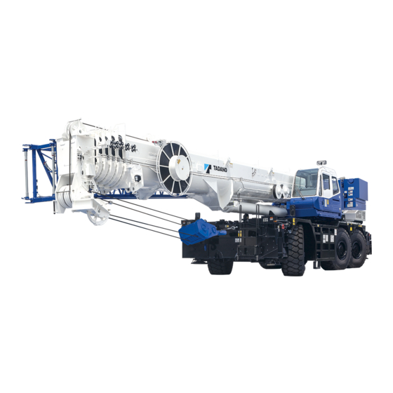
- Page 3 Foreword 2. External view The following is the traveling posture of the H-type outrigger specification machine. Front, rear, right, and left are the directions viewed from a position when operator sits on operator's seat with the boom directed to the front of the frame. Those directions remain invariant regardless of slewing direction of the superstructure.
- Page 4 Foreword 3. Outline of specifications Spec. No. GR-1600-2-00103 GR-1600-2-00104 Item 2M2D (South America, South Africa) No. of boom sections No. of jib stages (base (jib1), top (jib2)) Single top Fitted Manual offset jib Hydraulic offset jib (Fix jib) (Power tilt jib) Main winch Fitted Auxiliary winch...
- Page 5 Foreword 4. Conversion table Length millimeter centimeter meter inch foot mile kilometer in, ” ft, ’ 1×10 1×10 3.93701×10 3.28084×10 1.60934 1×10 1×10 3.93701×10 3.28084×10 6.21373×10 1×10 1×10 3.93701×10 3.28084 2.54×10 2.54 2.54×10 8.33333×10 3.048×10 3.048×10 3.048×10 1.2×10 Speed km/h mile/h, mph 6.21373×10 1.60934...
- Page 6 Foreword Mass gram kilogram ounce pound metric ton short ton s. t 1×10 3.5274×10 2.20462×10 1×10 1.10231×10 1×10 3.5274×10 2.20462 1×10 1.10231×10 2.83495×10 2.8349×10 6.25×10 2.83495×10 3.12494×10 4.53592×10 4.53592×10 1.6×10 4.53592×10 5×10 1×10 1×10 3.5274×10 2.20462×10 1.10231 9.07185×10 9.07185×10 3.2×10 2×10 9.07185×10 Pressure...
- Page 7 Foreword 5. Drawing method of illustrations in this service manual The third angle projection method of mechanical drawing is used for the illustrations in this service manual. The third angle projection method is generally composed of the front view (the figure viewed from the front: A), top view (the figure viewed from the top: B), and right-side view (the figure viewed from the right: C) as shown below.
- Page 8 6. Group index Data, Adjustment and Checks System Diagrams WA04-5330E...
- Page 9 Foreword 7. Contents Spec. No. GR-1600-2-00103 GR-1600-2-00104 Section 2M2D (South America, South Africa) Data, Adjustment and Checks Service Data Adjusting Pressure (Hydraulic Pressure) Adjusting Pressure (Pneumatic Pressure) Air Bleeding Procedure Adjusting Procedure (Electric) Assembly Adjustment (Crane Operation) Assembly Adjustment (Traveling Device) Operation Check (Crane Operation) Operation Check (Traveling Device) Inspection and Maintenance...
- Page 10 Foreword Spec. No. GR-1600-2-00103 GR-1600-2-00104 Section 2M2D (South America, South Africa) Location of Installation Hydraulic Parts Location Diagram (Upper) Hydraulic Parts Location Diagram (Lower) Hydraulic Parts Location Diagram (Torque Converter) Pneumatic Parts Location Diagram Z-10 Electric Parts Location Diagram (Upper) Z-11 Electric Parts Location Diagram Z-12...
-
Page 11: Table Of Contents
Data, Adjustment and Checks Contents Y-1 Service Data ........1 Y-2 Adjusting Pressure (Hydraulic Pressure) ....13 Amounts of oil and coolant ......1 Location (position of relief valve etc.) ..13 Operating speed ........1 Items ............ 15 Hydraulic device ........2 Winch ............ - Page 12 Y-4 Air Bleeding Procedure ....30 Main winch drum rotation detection switch (CN591) ..... 42 Hydraulic pump ........30 Aux. winch drum rotation Gear pump..........30 detection switch (CN592) ..... 42 Variable piston pump ........ 30 Variable piston pump (when the tank Over-front detection switch (CN521) ..
- Page 13 Y-6 Assembly Adjustment Y-7 Assembly Adjustment (Crane Operation) ....53 (Traveling Device) ....66 Boom head adjustment ......53 Service brake adjustment ......66 Upper part of boom head ......53 Adjusting the brake pedal ......66 Lower part of boom head ......53 Tightening the cap of reserve tank of Stopper for boom full retraction ....
- Page 14 Y-8 Operation Check Y-9 Operation Check (Crane Operation) ....74 (Traveling Device) ....79 Outrigger status indicator ......74 Exhaust brake ......... 79 Hoisting........... 75 Automatic transmission ......79 Backward stability control......75 Overshift prevention ........ 80 Frontward stability control ....... 75 Maximum allowable speed ......
-
Page 15: Service Data
Service Data Service Data [NOTICE] Standard values are values at time of vehicle shipment from TADANO. Limit values are the limits at which adjustment or part replacement is necessary. 1. Amounts of oil and coolant (1L = 2.64172 × 10... -
Page 16: Hydraulic Device
Service Data 3. Hydraulic device 3.1 Hydraulic pump Item Standard value Remarks Speed reducing ratio 0.918 Idling (min 730 ± 27 Eng. 670 ± 25 Variable piston pump Max. (min 2342 Eng. 2150 (PTO - ON) –00 –00 Displacement (cm /rev) 82 + 82 Speed reducing ratio... -
Page 17: Hydraulic Cylinder
Service Data 3.3 Hydraulic cylinder (1 m = 3.28084 ft) (1 mm = 3.93701 × 10 Remarks Standard Item value Condition and method Safety and notice Inspection conditions 1. Boom angle: 60° ± 2° (Lowering operation) 2. Boom full retraction 3. - Page 18 Service Data Remarks Standard Item value Condition and method Safety and notice Inspection conditions 1. Angle lowered by 5° ± 2° from jib tilt angle upper limit (minimum offset angle) 2. Boom angle: 60° ± 2° 3. Engine stop 1° or less/ 4.
-
Page 19: Slewing Section
Service Data 4. Slewing section (1 mm = 3.93701 × 10 Item Standard value Remarks Horizontal play 5 mm or less Amount of slewing play Vertical play 2.5 mm or less 5. Boom section 5.1 Slide plate (1 mm = 3.93701 × 10 Standard Location used thickness... - Page 20 Service Data Standard Location used thickness Remarks (Boom) (mm) Upper Refer to Figure 1 (*1) Upper (on upper part of side face) Right/Left : each 1-piece Side (Standard) Front Right/Left : each 9-pieces Lower (on rounded face) (Standard) Telescopic or 22 Right/Left : each 0-pieces section 3 Upper (on oblique face)
-
Page 21: Boom Bending And Deformation
Service Data 5.2 Boom bending and deformation (1 mm = 3.93701 × 10 Item Standard value (mm) Remarks Overall boom bending No significant vertical or Set the machine (at full extension, maximum elevation angle, with horizontal bends shall be found level. -
Page 22: Jib Bending And Deformation
Service Data 5.3 Jib bending and deformation (1 mm = 3.93701 × 10 Item Standard value (mm) Remarks Check for bending of the whole jib a ≤ 11.8 a ≤ 1.5 + L /1000 No significant bending in vertical and L = 10300 horizontal direction shall be found. -
Page 23: Sheave
Service Data 5.5 Sheave (1 mm = 3.93701 × 10 Standard of Limit of Item minor diameter minor diameter Remarks (mm) (mm) (*1) Boom top upper 374.3 Determination of limit minor diameter Single top 434.3 (When rope of nominal diameter Only sheaves of the less than 25 mm are used) hoisting systems... -
Page 24: Criteria For Maintenance
Service Data 6. Criteria for maintenance and replacement of vehicle 6.1 Power transmission device Item Standard value Remarks Idling (min 670 ± 25 2860 ± 40 2150 Eco mode : OFF –00 (Reference value) Max. (min Check conditions ・PTO switch : OFF When torque converter stalls Approx. -
Page 25: Steering Device
Service Data 6.3 Steering device (1 mm = 3.93701 × 10 Item Standard value Remarks Cylinder side –0.025 –0.05 Pin outer diameter (mm) Rod side –0.025 –0.05 Clearance above and below axle (mm) 0 to 0.05 Camber (°) Caster (°) Kingpin angle (°) 1st axle +2.0 to +4.0... -
Page 26: Mass Table
Y-1 . Y-1 . Service Data 7. Mass table The dry weights of the major components are shown in the table below. Refer the weights, and select appropriate hoisting devices when removing and installing the component. Unit: kg (lb) Mass Assembly name Fix jib Power tilt jib... -
Page 27: Adjusting Pressure
Adjusting Pressure (Hydraulic Pressure) Adjusting Pressure (Hydraulic Pressure) 1. Location (position of relief valve etc.) WY02-2020E... - Page 28 Adjusting Pressure (Hydraulic Pressure) WY02-2020E...
-
Page 29: Items
2. Items 2.1 Winch [NOTICE] Oil temperature: 50 ± 5°C (122 ± 9°F) (Hydraulic oil: TADANO Hydraulic Oil LL) When not described to use the pressure check port, check the main pump pressure display on the AML display panel. Shift the control lever or switch while the engine is idling, then increase engine speed. - Page 30 Adjusting Pressure (Hydraulic Pressure) WY02-2020E...
-
Page 31: Elevating
Adjusting Pressure (Hydraulic Pressure) 2.2 Elevating [NOTICE] Oil temperature: 50 ± 5°C (122 ± 9°F) (Hydraulic oil: TADANO Hydraulic Oil LL) When not described to use the pressure check port, check the main pump pressure display on the AML display panel. -
Page 32: Telescoping
Adjusting Pressure (Hydraulic Pressure) 2.3 Telescoping [NOTICE] Oil temperature: 50 ± 5°C (122 ± 9°F) (Hydraulic oil: TADANO Hydraulic Oil LL) When not described to use the pressure check port, check the main pump pressure display on the AML display panel. - Page 33 Adjusting Pressure (Hydraulic Pressure) WY02-2020E...
-
Page 34: Steering
Adjusting Pressure (Hydraulic Pressure) 2.4 Steering [NOTICE] Oil temperature: 50 ± 5°C (122 ± 9°F) (Hydraulic oil: TADANO Hydraulic Oil LL) Shift the control lever or switch while the engine is idling, then increase engine speed. Engine Set pressure Item... -
Page 35: Slewing
Adjusting Pressure (Hydraulic Pressure) 2.5 Slewing [NOTICE] Oil temperature: 50 ± 5 °C (122 ± 9°F) (Hydraulic oil: TADANO Hydraulic Oil LL) When not described to use the pressure check port, check the main pump pressure display on the AML display panel. -
Page 36: Outrigger
Adjusting Pressure (Hydraulic Pressure) 2.6 Outrigger [NOTICE] Oil temperature: 50 ± 5 °C (122 ± 9°F) (Hydraulic oil: TADANO Hydraulic Oil LL) Shift the control lever or switch while the engine is idling, then increase engine speed. Engine Set pressure... -
Page 37: Remote Control Pilot Pressure
Adjusting Pressure (Hydraulic Pressure) 2.7 Remote control pilot pressure [NOTICE] Oil temperature: 50 ± 5 °C (122 ± 9°F) (Hydraulic oil: TADANO Hydraulic Oil LL) Shift the control lever or switch while the engine is idling, then increase engine speed. Engine... -
Page 38: Flow Control Valve
Adjusting Pressure (Hydraulic Pressure) 2.8 Flow control valve [NOTICE] Oil temperature: 50 ± 5 °C (122 ± 9°F) (Hydraulic oil: TADANO Hydraulic Oil LL) Shift the control lever or switch while the engine is idling, then increase engine speed. Engine... -
Page 39: Counterweight Cylinder Relief Valve
Adjusting Pressure (Hydraulic Pressure) 2.10 Counterweight cylinder relief valve [NOTICE] Oil temperature: 50 ± 5 °C (122 ± 9°F) (Hydraulic oil: TADANO Hydraulic Oil LL) Engine Set pressure Item Check procedure speed (Mark) kgf/cm (min Already the pressure is set by the valve Relief value 12.0 ±... -
Page 40: B/C-Pin Relief Valve
Adjusting Pressure (Hydraulic Pressure) 2.11 B/C-pin relief valve [NOTICE] Oil temperature: 50 ± 5 °C (122 ± 9°F) (Hydraulic oil: TADANO Hydraulic Oil LL) Engine Set pressure Item Check procedure speed (Mark) kgf/cm (min Already the pressure is set by the valve Relief value 12.0 ±... -
Page 41: B/C-Pin Pressure Reducing Valve
Adjusting Pressure (Hydraulic Pressure) 2.12 B/C-pin pressure reducing valve [NOTICE] Oil temperature: 50 ± 5 °C (122 ± 9°F) (Hydraulic oil: TADANO Hydraulic Oil LL) Engine Set pressure Item Check procedure speed (Mark) kgf/cm (min 1. Connect a pressure gauge to the pressure check port (R). -
Page 42: Jib Tilt (Only Power Tilt Spec.)
2.13 Jib tilt (only power tilt spec.) [NOTICE] Oil temperature: 50 ± 5 °C (122 ± 9°F) (Hydraulic oil: TADANO Hydraulic Oil LL) When not described to use the pressure check port, check the main pump pressure display on the AML display panel. - Page 43 Y-3 . Y-3 . Adjusting Pressure (Pneumatic Pressure) Adjusting Pressure (Pneumatic Pressure) Set pressure No. in circuit Item Remarks diagram kgf/cm Pressure regulator Check that the air dryer Turning on pressure 710 ± 20 7.2 ± 0.2 103 ± 3 recovers its performance during +0.3...
-
Page 44: Air Bleeding Procedure
Air Bleeding Procedure Air Bleeding Procedure 1.2 Variable piston pump 1. Hydraulic pump 1. Fill the hydraulic oil tank with the hydraulic oil. (If the suction section is disassembled due to repair [NOTICE] or other reasons, bleed from the air-bleed plug on Be sure that the following conditions are met before the suction side as described above.) starting the engine. -
Page 45: Variable Piston Pump (When The Tank Pressurization Tool Is Used)
Air Bleeding Procedure 1.3 Variable piston pump (when the tank 6. If any abnormality is found, bleed the hydraulic pressurization tool is used) pump again. [NOTICE] 7. If there is no abnormal noise, turn ON the PTO Adjust the pressure setting of the tank pressurization tool to 15 kPa (0.15 kgf/cm²) (2.2 psi). -
Page 46: Winch Brake
Air Bleeding Procedure 2. Winch brake [NOTICE] To avoid damage to the friction plates of the winch brakes, bleed the winch brakes following the procedures below. 1. When assembling piping, plug the piping between the hoisting down port of the main winch motor and the corresponding hydraulic pilot control valve (main 1 and 2). -
Page 47: Service Brake
Air Bleeding Procedure 3. Service brake 4. Hydraulic motor assy [NOTICE] 4.1 Slewing motor The vehicle has two boosters; one for the front [NOTICE] wheel brakes and the other for the rear wheel brakes. Do not apply any load to the motor before completing air bleeding. -
Page 48: Winch Motor
Air Bleeding Procedure 4.2 Winch motor 5. Winch counterbalance valve (main and auxiliary) [NOTICE] Do not apply any load to the motor before [NOTICE] completing air bleeding. Bleed the main and auxiliary winch circuits by following the procedures below. The procedures are 1. -
Page 49: Slewing Control Valve
Air Bleeding Procedure 6. Slewing control valve 7. Pilot circuit (back-pressure valve) (slewing valve, hydraulic pilot control valves) [NOTICE] Conditions [NOTICE] Engine speed : Max. (2150 min Conditions : ON Engine speed : idling (670 min Slewing brake : ON : ON Oil temperature : 50°C (122°F) or higher 1. -
Page 50: Positive Control
Air Bleeding Procedure 8. Positive control 5 Jib tilt While any of the crane operations described in Mount the jib, and pull out the connector (CN100) section 7. is performed, loosen the air-bleed plug of the AML vent solenoid valve. near the lower pump to bleed the positive control Move the jib tilt lever fully to the jib lowering side. -
Page 51: Hydraulic Valve (Winch Brake)
Air Bleeding Procedure 9. Hydraulic valve (winch brake) 10. Cylinder circuits Loosen the air-bleed plug on the pilot check valve [NOTICE] for each cylinder described below. In this state, Bleed this valve after the pilot circuit (hydraulic pilot control valve) (See the section 7.) and the positive repeat each cylinder operation to retract or extend control (See the section 8.) are bled. - Page 52 Y-4 . Y-4 . Air Bleeding Procedure (4) Boom pivot pin mounting/dismounting cylinder (6) Outrigger mounting/dismounting cylinder (Front side) (Rear side) (5) Elevating pivot pin inserting/extracting cylinder △ 345-807-13000 WY05-5000E...
-
Page 53: Adjusting Procedure (Electric)
Adjusting Procedure (Electric) Adjusting Procedure (1) C-pin lock detection switch 1 (CNC1) (Electric) 1. B-pin, C-pin detection switch (For reference) Dimension E: 5.5 mm (0.22 in) Move the switch closer to the target by (CNC1 to C8) △ 344-312-50000 +0.5 +0.02 mm (0.06 in) from the position where... -
Page 54: Boom Section Detection Switch
Adjusting Procedure (Electric) 2. Boom section detection switch • Make sure that the dimension X is 336 ± 3 mm (CNRL etc.) △ 344-312-50000 (13.2 ± 0.1 in). • Make sure that the dimension Y is 68 ± 2 mm (2.68 ±... -
Page 55: Jib Stowed Detection Switch (Cn572)
Adjusting Procedure (Electric) 3. Jib stowed detection switch (CN572) 4. Jib lock pin retraction detection switch (CN573) △ △ 343-546-42000 343-550-62000 △ △ 343-543-42000 343-553-62000 △ △ 343-546-42000 343-550-62000 Adjust the switch position so that the dimension A △ △ 343-543-42000 343-553-62000 +0.5... -
Page 56: Main Winch Drum Rotation
Adjusting Procedure (Electric) △ Applicable serial No. :FE5098 - - 5. Main winch drum rotation detection 6. Aux. winch drum rotation detection switch (CN591) switch (CN592) △ △ 343-728-80000 343-728-70000 Adjust the switch position so that the dimension A Follow the same procedure as that in main winch becomes 2.5 ±... -
Page 57: Over-Front Detection Switch (Cn521)
Adjusting Procedure (Electric) △ Applicable serial No. :FE5098 - - 7. Over-front detection switch (CN521) 8. Control lever stand position detection switch (left) (CN529) △ 349-521-30000 Fully retract the boom and slew it to the over-front. △ 343-233-81000 △ 343-234-41000 Insert the slewing lock pin and set the boom angle to Set the clearance B to minimum, and adjust switch 0°. -
Page 58: Straight Ahead Detection Switch
Adjusting Procedure (Electric) △ Applicable serial No. :FE5109 - - 9. Straight ahead detection switch 10. Counterweight equipped detection (CN408) switch (left) (CN457) △ 349-609-70000 △ △ 349-610-10000 343-543-50000 Set the rear wheels in a straight-forward position, Adjust the switch position so that the dimension A and adjust the switch position so that the dimension becomes 4.5 mm (0.18... -
Page 59: Counterweight/Boom
Adjusting Procedure (Electric) 12. Counterweight/boom mounting (2) Adjusting the switch /dismounting position detection • Install the proximity switches (right)/(left) to the switch (right) (CN1538) and base plate (slewing table side) under the cab. switch (left) (CN1539) • Connect CN1538 to the switch (right) and CN1539 △... -
Page 60: Front Side Adjusting Procedure
Adjusting Procedure (Electric) 12.2 Front side adjusting procedure (GR-1600XL only) [NOTICE] Adjust with slewing the boom forward and elevating the boom at around 70°. (1) Installing the front side detection support • Install the front detection support so that the bolt comes the center of the slotted hole. -
Page 61: Cab Tilt Stowed Detection Switch
Adjusting Procedure (Electric) 13. Cab tilt stowed detection switch 14. Over-unwinding detection switch (CN1155) (main winch) (option) △ 342-615-15000 △ (CN595) 344-451-40000 When the cab is stowed, adjust the switch position △ 344-457-80000 so that the dimension A becomes 3.0 ± 0.5 mm Adjust the roller assy position by the bolt Z so that (0.12 ±... -
Page 62: Vehicle Height Detection
Adjusting Procedure (Electric) 16. Vehicle height detection △ 347-907-32000 △ 347-908-52000 16.1 Assembly adjustment [NOTICE] Before making this adjustment, complete the adjustments in "16.2" and "16.3". 1. Adjust the vehicle height to the normal traveling state. (1) Direct the boom to the front or rear. (2) Press the suspension up/down switch so that the dimension H becomes 178 ±... - Page 63 Adjusting Procedure (Electric) △ Applicable serial No. :FE5102 - - Rear right 3. Check that the switch satisfies the operating conditions in the table below. (When the switch is turned ON, the LED lights up in green △ orange.) Rear left Rear right Suspension...
-
Page 64: Switch Adjustment (Rear Left: Cn404, Cn405)
Adjusting Procedure (Electric) △ Applicable serial No. :FE5102 - - 16.2 Switch adjustment (rear left: CN404, CN405) △ 347-904-36000 △ 347-907-56000 1. Apply a thread locking agent (ThreeBond 1401 or 3. Adjusting right switch (CN405) the equivalent) to the threaded sections of the left Adjust the clearance M between the right switch and right switches beforehand. -
Page 65: Switch Adjustment (Rear Right: Cn406, Cn407)
Adjusting Procedure (Electric) △ Applicable serial No. :FE5102 - - 16.3 Switch adjustment (rear right: CN406, CN407) △ 347-904-35000 △ 347-907-56000 1. Apply a thread locking agent (ThreeBond 1401 or 3. Adjusting right switch (CN407) the equivalent) to the threaded sections of the left Adjust the clearance M between the right switch and right switches beforehand. -
Page 66: Slewing Lock Detection Switch (Cn1154)
Y-5 . Y-5 . Adjusting Procedure (Electric) 17. Slewing lock detection switch (CN1154) △ 343-821-50000 △ △ 343-546-42000 343-550-62000 △ △ 343-543-42000 343-553-62000 Set the slewing lock to be free, and adjust the switch position so that the dimension A becomes 2.0 ±... -
Page 67: Assembly Adjustment
Assembly Adjustment (Crane Operation) Assembly Adjustment 1.2 Lower part of boom head (Crane Operation) The bolt should be touched softly to the surface Y. 1. Boom head adjustment Then, tighten the nut. Apply a thread locking agent (ThreeBond 1305 or 1.1 Upper part of boom head the equivalent) to the threaded section. -
Page 68: Stopper For Boom Full Retraction
Assembly Adjustment (Crane Operation) 1.3 Stopper for boom full retraction (1) Check the contact condition of the each stopper at assembling. (2) Unsuitable phenomenon, for example one-side hitting, shall be improved. If you grind the contact surface, machining allowance shall be 2 mm (0.08 in) or less. -
Page 69: Boom Clearance Adjustment
Assembly Adjustment (Crane Operation) 2. Boom clearance adjustment (3) The dimension C between the upper and lower slide plate shall be 164 ± 0.5 mm (6.46 ± 0.02 in). [NOTICE] The adjustment of the dimension shall be by The term “minimum clearance” means the inserting shims to the upper slide plate side. -
Page 70: Shim Adjustment At The Lower Part Of The Boom Bottom (Inner Box)
Assembly Adjustment (Crane Operation) 2.2 Shim adjustment at the lower part of the boom bottom (inner box) (Section [2]) (1) Insert the shims in accordance with Table 1. Then inner box shall be inserted to the outer box until the slide plates are covered with the outer box. (2) Check no interference between the slide plates and the retainer in the outer box. -
Page 71: Shim Adjustment At The Upper Part Of The Boom Bottom (Inner Box)
Assembly Adjustment (Crane Operation) 2.3 Shim adjustment at the upper part of the (4) Apply a thread locking agent (ThreeBond 1401 or boom bottom (inner box) the equivalent) to the bolt. (Section [3]) (Table 2) Standard number of shims Dimension D (one side) Between 1.2-mm shim: 0,... -
Page 72: The Boom Bottom (Inner Box)
Assembly Adjustment (Crane Operation) 2.4 Shim adjustment at the side of the boom bottom (inner box) (Section [4]) (1) The clearance between the slide plate and the outer box shall be adjusted at the entrance of the outer box. (2) The clearance shall be as minimum clearance. Apply a thread locking agent (ThreeBond 1401 or the equivalent) to the bolt. -
Page 73: Shim Adjustment At The Lower Part Of The Boom Head (Outer Box)
Assembly Adjustment (Crane Operation) 2.5 Shim adjustment at the lower part of the (3) Refer to Table 4 about the amount of shim. boom head (outer box) (Table 4) (Section [5]) Standard number Number of of shims side plate (each side) (each side) Between 0.6-mm shim: 1,... -
Page 74: Shim Adjustment At The Upper Part Of The Boom Head (Outer Box)
Assembly Adjustment (Crane Operation) 2.6 Shim adjustment at the upper part of the (4) Final adjustment: boom head (outer box) After telescoping the boom several times, adjust (Section [6]) with maintenance telescoping mode. In the state that the inner box is extended 1 m (3.28 ft) from the boom full retraction, adjust the shims so that the clearance shall be as minimum clearance at both left and right side. -
Page 75: Shim Adjustment At The Lower Oblique
Assembly Adjustment (Crane Operation) 2.7 Shim adjustment at the lower oblique sides (3) Apply a thread locking agent (ThreeBond 1401 or of the boom bottom (inner box) the equivalent) to the bolt. (Section [7]) (Table 6) Standard number of shims (per point) Between 1-mm shim: 3,... -
Page 76: Slide Plate Adjustment At The Side Of The Boom Head (Outer Box)
Assembly Adjustment (Crane Operation) 2.8 Slide plate adjustment at the side of the Telescopic section 1 to Telescopic section 4 boom head (outer box) Extend the inner box fully. In that state adjust the (Section [8]) shims so that the inner box is aligned to the center of the outer box. -
Page 77: Counterweight Cylinder Synchronization Adjustment
Assembly Adjustment (Crane Operation) 3.1 Adjustment without counterweight 3. Counterweight cylinder (rough adjustment) synchronization adjustment 1. Extend the cylinders without the counterweight, WARNING and measure the stroke difference between the right and left cylinders. (Measure the remaining If the speed of each cylinder differs excessively during adjustment and the counterweight stroke of the cylinder extending slower when the inclines significantly, stop adjustment. -
Page 78: Adjustment With Counterweight (Regular Adjustment)
Assembly Adjustment (Crane Operation) 3.2 Adjustment with counterweight 3. After the adjustment, fix the choke bolt with lock (regular adjustment) nuts. After the choke bolt is fixed, check again if 1. Connect the counterweight cylinder rod end and the stroke difference between the right and left the slewing table with the pin. - Page 79 Y-6 . Y-6 . Assembly Adjustment (Crane Operation) 2. Extend the cylinders with the counterweight. (The [NOTICE] counterweight is lowered.) Check the stroke If the stroke difference between the right and left difference between the right and left cylinders. cylinders is 20 mm (0.8 in) or less, adjustment is not necessary.
-
Page 80: Assembly Adjustment
Assembly Adjustment (Traveling Device) Assembly Adjustment 1.3 Check after replacing brake hose (Traveling Device) After you replace the brake hoses and so on, 1. Service brake adjustment make sure that any contact does not occur between the hoses and the structures in any 1.1 Adjusting the brake pedal situation. -
Page 81: Accelerator Adjustment
Assembly Adjustment (Traveling Device) 2. Accelerator adjustment 2.1 Accelerator pedal 1. Adjust bolt F so that lever I is vertical, then lock the bolt with the nut. 2. Move the accelerator sensor lever so that it contacts stopper C. Then adjust nut H until there is no pedal play. -
Page 82: Engine Speed
Assembly Adjustment (Traveling Device) 3. Engine speed 5. Adding oil to the torque converter and transmission [NOTICE] Before checking the engine speed, run the engine [NOTICE] to warm it up. (Torque converter oil temperature When checking the oil level, turn PTO OFF and turn should reach approximately 50°C (122°F).) the air conditioner OFF. -
Page 83: Axle Alignment Adjustment Procedure
6. Axle alignment adjustment procedure [NOTICE] This section describes the adjustment procedure performed in the TADANO manufacturing line. 6.1 Aligning the axles 1. On a firm level surface, perform the suspension 3. If there is a dimensional deviation, adjust the level adjustment. -
Page 84: Adjusting The Side Slip And Axle Slip
Assembly Adjustment (Traveling Device) 6.2 Adjusting the side slip and axle slip 1. On a firm level surface, perform the suspension 4. When adjusting the drag link, adjust the steering level adjustment. lever with the dimensions as shown below. 2. Align each axle in the straight ahead condition. 5. -
Page 85: Tire And Steering Angle Adjustment
Assembly Adjustment (Traveling Device) 7. Tire and steering angle adjustment 7.1 Tire size and air pressure 1. Tire size: 26.5 R25 +100 2. Air pressure: 650 kPa (6.5 kgf/cm –000 –0 +14.5 (92.5 psi) –00.0 7.2 Adjusting the steering angle of axle 4. -
Page 86: Hydraulic Suspension
Assembly Adjustment (Traveling Device) 8. Hydraulic suspension 8.1 Releasing pressure in the accumulators for hydraulic suspension When disassembling the components and pipings in the hydraulic suspension, release pressure in the accumulators beforehand in the method described below. 1. Perform vehicle height increasing operation of the crane in on-rubber operation configuration. -
Page 87: Parking Brake Adjustment
Y-7 . Y-7 . Assembly Adjustment (Traveling Device) 9. Parking brake adjustment 9.1 Connecting the parking brake and brake chamber (1) Shift the rod of the brake chamber to the end of its stroke. (Use air pressure to move it to the end of its extension stroke.) Then adjust the position of end, connect the chamber and brake lever. -
Page 88: Operation Check
Operation Check (Crane Operation) Operation Check Main switch : ON (Crane Operation) : ON 1. Outrigger status indicator Shift lever : N position Outrigger extension width: 8.2 m (26.9 ft) Main switch : ON Boom : Over-side : ON (Slewing angle: 90° or 270°) Shift lever : Not in N position Boom... -
Page 89: Hoisting
Operation Check (Crane Operation) 2. Hoisting 5. Outrigger emergency setting [Condition] • Load : None • Engine speed : Approximately 670 min to medium speed [Procedure] 1. Shift the boom telescoping lever to full stroke first. 2. Make sure that the main winch moves slowly 1. -
Page 90: Warning
Operation Check (Crane Operation) 7. Warning [NOTICE] For the location of the buzzers, refer to "Z-11 Electric Parts Location Diagram (Upper), 1. Inside cab". Warning Item Sound Check conditions buzzer • 280 Hz Buzzer sounds at 100% when main switch is ON and PTO Buzzer 3 AML limit •... -
Page 91: Aml Indicator
Operation Check (Crane Operation) 10. AML indicator 11. AML indicator (O/R mounting/dismounting) (boom mounting/dismounting) Main switch: ON Main switch : ON PTO: ON : ON Counterweight : 0 t Boom angle : 20° - 40° Boom : Over-rear Disconnect the joint connector (front: (Slewing angle :180°) CN1528, rear: CN1529) from outrigger Outrigger extension width: 8.2 m (26.9 ft) -
Page 92: Outrigger Slide Plate Adjustment
Y-8 . Y-8 . Operation Check (Crane Operation) 12. Outrigger slide plate adjustment 1. With the outriggers fully retracted, install the slide plate and the plate into the outrigger box. 2. Adjust the slide plate with the bolts X so that the slide plate is 2 mm (0.08 in) away from the upper surface of outer outrigger box bottom plate. -
Page 93: Operation Check
Operation Check (Traveling Device) Operation Check 2. Automatic transmission (Traveling Device) [1 km/h = 0.6214 mph] [NOTICE] 1. Exhaust brake Numbers indicate speedometer readings (units: km/h) [NOTICE] ( ) Indicates lock up ON and OFF values. Jack up the crane and make sure the crane is set Make sure that the transmission shifts according to up horizontally and all tires are off the ground. -
Page 94: Overshift Prevention
Operation Check (Traveling Device) 3. Overshift prevention 4. Maximum allowable speed [1 km/h = 0.6214 mph] Units: km/h (mph) [NOTICE] Combination meter High position Low position Jack up the vehicle and shift to 4WD High position. display Perform the operations below and check the shift (5.5) 2.5 (1.6) position with the combination meter. -
Page 95: Steering Mode Change
Operation Check (Traveling Device) 5. Steering mode change Change the steering mode switch to 6-wheel, crab or rear steering. Turn the steering wheel, and check the steering. Check that the indicator (in the right bottom of the instrument panel, green) is ON, except when rear wheels are out of straight ahead condition. -
Page 96: Warning
Operation Check (Traveling Device) 7. Warning [NOTICE] For the location of the buzzer, refer to "Z-11 Electric Parts Location Diagram (Upper), 1. Inside cab". [1 km/h = 0.6214 mph] Warning Item Sound Check conditions buzzer Buzzer sounds when the following conditions are met. Total air low 1. -
Page 97: Hydraulic Suspension
Operation Check (Traveling Device) 9. Hydraulic suspension Flashes slowly: 0.8 second interval, Flashes fast: 0.4 second interval 9.1 Normal operation Check the suspension state and the suspension lock indicator with the following procedure. Suspension lock indicator Operation Suspension state Turn ON the main switch to start engine. - Page 98 Operation Check (Traveling Device) Suspension lock indicator Operation Suspension state Extend the slides by the outrigger Lights up Locked operation switch (central/individual) and jack up the Suspension falls rapidly if the suspension free switch is pressed while crane. the boom is in front and the crane is in the jack-up state. Set the outrigger status on the Do not operate the switch.
-
Page 99: Emergency Operation
Operation Check (Traveling Device) 9.2 Emergency operation Flashes slowly: 0.8 second interval, Flashes fast: 0.4 second interval Check the suspension state and the suspension lock indicator with the following procedure. Suspension lock indicator Operation Suspension state Turn ON the main switch to start engine. - Page 100 Operation Check (Traveling Device) Suspension lock indicator Operation Suspension state Extend the slides by the outrigger Flashes slowly Locked operation switch (central/individual) and jack up the Suspension falls rapidly if the suspension free switch is pressed while crane. the boom is in front and the crane is in the jack-up state. Set the outrigger status on the Do not operate the switch.
- Page 101 Operation Check (Traveling Device) Suspension lock indicator Operation Suspension state Flashes fast Suspension emergency free Keep pressing the suspension free switch for 1 second or more. ↓ Turn OFF the main switch to stop Locked engine. ↓ Turn ON the main switch to start Flashes slowly Locked engine.
-
Page 102: Off-Straight-Ahead Wheel Indicator And Warning
Y-9 . Y-9 . Operation Check (Traveling Device) 10. Off-straight-ahead wheel indicator and warning [NOTICE] Jack up the vehicle. Engine speed: idling (670 min Check the following. Status of off-straight Warning Orientation of Steering Operation buzzer -ahead rear wheel mode wheel (CN818) indicator... -
Page 103: Inspection And Maintenance
Y-1 0 . Y-1 0 . Inspection and Maintenance Y-10 Inspection and Maintenance 1. Refer to “Inspection and Maintenance” in “Operation Manual” of its applicable crane. 2. Maintenance of line filter Maintenance table Inspection and maintenance interval Type of Points Parts No. -
Page 104: And Thread Size Table
Y-1 1 . Y-1 1 . Boom Connecting Pin and Thread Size Table Y-11 Boom Connecting Pin and Thread Size Table (Note): “ ” means that more than one spec. No. are applicable. (Unit: mm) (1 mm = 0.039 inch) GR-1600-2- GR-1600-3- Applicable spec. - Page 105 System Diagrams Contents Z-1 Hydraulic Circuit ......1 Electric circuit .......... 11 Electric circuit (crane, main)...... 11 Comparison table of hydraulic parts Electric circuit (ESP) ......... 12 (part No., part name, Electric circuit (slewing table, right) ..13 coordinate and location) ....1 Electric circuit (slewing table, left) .....
- Page 106 Z-6 Electric Circuit (Lower) ....31 15. Self-removable C/W ........ 53 Composition of 16. Removable boom system (option) ... 55 the electric circuit diagram ... 31 17. Cab tilt ............ 56 Comparison table (connector No., usage, coordinate and paragraph No.) ..32 Z-8 Hydraulic Parts Location Diagram Electric circuit..........
- Page 107 Z-11 Electric Parts Location Diagram Z-13 Electric Parts Location Diagram (Upper) ........67 (ICF, SCT) ....... 85 Inside cab ..........67 ............ 85 Slewing table, boom ........ 68 ............ 86 Fix jib ............68 Power tilt jib ..........69 Z-14 Electric Parts Location Diagram (Lower) ........
- Page 108 Harness (two-blocking) ......104 Harness (O/R front) ....... 125 Boom ............104 Harness (O/R rear) ........ 126 Single top..........105 Jib1 ............106 Jib2 ............107 Z-18 Searchlight, Anemometer, Aviation Obstruction Light Harness (AML lamp) ......108 (Option) ......... 127 10. Harness (ESP) ........109 Structure ..........
- Page 109 General view ..........144 Searchlight..........144 Anemometer ........... 145 3.2.1 FE5027 ..........145 3.2.2 FE5028-- .......... 146 Aviation obstruction light ......147 3.3.1 FE5027 ..........147 3.3.2 FE5028-- .......... 148 Harness ..........149 Harness (boom searchlight) ....149 Harness (searchlight) ......150 Harness (slewing table, right) (option) ...
-
Page 110: Hydraulic Circuit
Hydraulic Circuit “Location” shows each applicable paragraph No. of this manual’s contents. Refer to the contents. Hydraulic Circuit 1. Comparison table of hydraulic parts (part No., part name, coordinate and location) Hydraulic Hydraulic Hydraulic circuit Location circuit Location circuit Location Part No. - Page 111 Hydraulic Circuit Z - 1 Z - 1 Hydraulic Hydraulic Hydraulic Location Location Location Part No. Part name circuit Part No. Part name circuit Part No. Part name circuit coordinate coordinate coordinate 63-12 Slewing left detection switch (CN541) Z-7 12. Slewing lock pin cylinder D-13 Z-7 5.
-
Page 112: Hydraulic Circuit Diagram
Z-1. Z-1. Z-1. Hydraulic Circuit 2. Hydraulic circuit diagram [NOTICE] 1) When the optional emergency steering is not installed, two points "A" are directly joined and three portions "※1" are plugged. (Front;left steering) (前軸;左ステアリング) 2) When the "Spec α (Power tilt jib)" is not installed, the "Spec β (FIx jib)" is installed SL33 25-1 1Right... -
Page 113: Torque Converter Circuit
Z- 2. Z- 2. Z- 2. Torque Converter Circuit Torque Converter Circuit (Parts, location: refer to Z-9) 250 Torque converter case 258 Transmission case G3/8 G3/8 Lubrication relief valve Oil cooler M16×1.5 Thermo sensor (T/C oil temp.) (CN427) SL45 G3/8 G3/8 SL43 Lock up... -
Page 114: Pneumatic Circuit
Z- 3. Z- 3. Z- 3. Pneumatic Circuit (1L=2.64172×10 gal) Pneumatic Circuit Center joint (Parts, location: refer to Z-10) Brake valve Air pressure switch (stop lamp) (contact close : depressing brake pedal) (CN568) Operating pressure : 29 –10 (0.3 +0.2 kgf/cm –0.1 (1st axle) - Page 115 Z- 4 Z- 4 Z- 4 Electric Circuit (Upper) (Crane) Z-4 Electric Circuit (Upper) (Crane) 1. Composition of the electric circuit diagram The electric circuit diagram of this machine is composed of “Z-4 (Upper) (Crane)”, “Z-5 (Upper) (Carrier)” and “Z-6 (Lower)” mainly. [NOTICE] The electric circuit (upper) (crane) is shown by following block diagram.
-
Page 116: Notational Convention
Electric Circuit (Upper) (Crane) 2. Reading method of electric circuit 5) Shield line (GND) diagram Wire to establish GND by diverging another wire to the shield line 2.1 Notational convention S – AA Wire distinction ■Conditions Wire number symbol 1. -
Page 117: Comparison Table (Connector No., Usage, Coordinate And Paragraph No.)
Electric Circuit (Upper) (Crane) “Electric circuit diagram” and “Harness diagram” show each applicable paragraph No. of this manual’s contents. Refer to the contents. 3. Comparison table (connector No., usage, coordinate and paragraph No.) Electric Electric Electric Electric Electric Electric Harness Harness Harness CN No. - Page 118 Electric Circuit (Upper) (Crane) Z - 4 Z - 4 Electric Electric Electric Electric Electric Electric Harness Harness Harness CN No. Usage circuit circuit CN No. Usage circuit circuit CN No. Usage circuit circuit diagram diagram diagram coordinate diagram coordinate diagram coordinate diagram...
-
Page 119: Electric Circuit
Electric Circuit (Upper) (Crane) Electric Electric Harness CN No. Usage circuit circuit diagram coordinate diagram B/C-pin lock/unlock detection relay Slewing lock warning lamp relay Air conditioner compressor block relay 2 Cab tilt alarm buzzer disable relay B-12 Cab tilt stowed detection relay B-13 JC01 C-18... - Page 120 Jib mounting operation signal (787AA) LG/Y Jib stowing operation signal CN821 CN817A (250AU) LG For AML vent solenoid (emergency) R48: GR-1450EX-2: R48: GR-1600XL-2: Buzzer 4 (two-blocking warning) (257AA) Y/O Emergency operation relay To Z-4 4.11 Electric Circuit (B09AP) B CN817B (335AA) V...
-
Page 121: Electric Circuit (Esp)
Electric Circuit (Upper) (Crane) 4.2 Electric circuit (ESP) [NOTICE] AML-C(ESP) 1. If not specified, wire type is CAVS and wire size is 0.5mm CN658 2. The following symbols indicate connection between same numbered wirings. (832AA) LG BOOT Reception side of GND : Supplying side : (830AA) L/R (834AA) BR... -
Page 122: Electric Circuit (Slewing Table, Right)
Z- 4 Z- 4 Z- 4 Electric Circuit (Upper) (Crane) 4.3 Electric circuit (slewing table, right) [NOTICE] 1. If not specified, wire type is AVS and wire size is 0.5mm SL121 SL120 SL162 Slewing left proportional Slewing right proportional Slewing relief proportional control valve control valve control valve... -
Page 123: Electric Circuit (Slewing Table, Left)
(261AA) W (contact open: hoisting up) (261AA) W To circuit (for separated transport) CN546 Main winch hoisting up detection switch GR-1600XL-2 Bridging device To circuit (AML override) Main winch hoisting down (250AI) LG (262AA) W/R CN1527 Main winch hoisting down detection switch... -
Page 124: Electric Circuit (For Separated Transport)
Electric Circuit (Upper) (Crane) 4.5 Electric circuit (for separated transport) [NOTICE] 1. If not specified, wire type is AVS and wire size is 0.5mm Over-unwinding detection switch(aux.) CN596 (279AA) BR/W (b-contact (normal close) open: over-unwinding) (option) (470AA) LG/Y CN596 (279AA) BR/W CN1527 (C01-001) -
Page 125: Electric Circuit (Boom, Fix Jib)
Z- 4 Z- 4 Z- 4 Electric Circuit (Upper) (Crane) 4.6 Electric circuit (boom, fix jib) [NOTICE] 1. If not specified, wire type is AVS and wire size is 0.5mm To circuit (AML, fix jib) CN853A CN888 (233AA) Y/B 1.25 (233AA) Y/B (C01-001) B/1-... -
Page 126: Electric Circuit (Boom, Power Tilt Jib)
Z- 4 Z- 4 Z- 4 Electric Circuit (Upper) (Crane) Applicable serial No. : FE5028-- 4.7 Electric circuit (boom, power tilt jib) [NOTICE] 1. If not specified, wire type is AVS and wire size is 0.5mm To circuit (AML, power tilt jib) CN853A CN888 (233AA) Y/B... -
Page 127: Electric Circuit (Boom, Esp)
Z- 4 Z- 4 Z- 4 Electric Circuit (Upper) (Crane) 4.8 Electric circuit (boom, ESP) [NOTICE] 1. If not specified, wire type is AVS and wire size is 0.5mm CNV4 B/C-pin selection solenoid valve (SOL V4) (energized: B-pin) CNV5 B/C-pin lock solenoid valve (SOL V5) (energized: lock) CNC6 B-pin lock detection switch (right) -
Page 128: Electric Circuit (Aml, Fix Jib)
Z- 4 Z- 4 Electric Circuit (Upper) (Crane) Z- 4 Applicable serial No. : FE5074-- 4.9 Electric circuit (AML, fix jib) [NOTICE] 1. If not specified, wire type is CAVS and wire size is 0.5mm To circuit (boom, fix jib) CN1595 (S01-015) R Detector power supply (+5V) -
Page 129: Electric Circuit (Aml, Power Tilt Jib)
Z- 4 Z- 4 Z- 4 Electric Circuit (Upper) (Crane) Applicable serial No. : FE5068-- 4.10 Electric circuit (AML, power tilt jib) [NOTICE] 1. If not specified, wire type is CAVS and wire size is 0.5mm To circuit (boom, power tilt jib) To circuit (crane, main) To circuit (boom, power tilt jib) CN961... -
Page 130: Electric Circuit (Aml Override)
Electric Circuit (Upper) (Crane) 4.11 Electric circuit (AML override) [NOTICE] 1. If not specified, wire type is CAVS and wire size is 0.5mm To circuit (carrier, main) PTO switch CN509 (154AA) Y CN1104 PTO power supply (022AA) G (022AA) G PTO signal (336AA) P (335AA) V... -
Page 131: Electric Circuit (Boom, Two-Blocking)
Electric Circuit (Upper) (Crane) 4.12 Electric circuit (boom, two-blocking) [NOTICE] 1. If not specified, wire type is AVS and wire size is 0.5mm To circuit (boom, fix jib) To circuit (boom, power tilt jib) CN859 Two-blocking detection switch (boom) (right) (contact open: two-blocking) CN862 (816AA) LG/B... -
Page 132: Electric Circuit (Jib, Single Top, Two-Blocking)
Z- 4. Z- 4. Z- 4. Electric Circuit (Upper) (Crane) Applicable serial No. : FE5028-- 4.13 Electric circuit (jib, single top, two-blocking) Short jib (not used) When operating s hort jib , (C06-018) W (C06-018) W connect this connector. (C06-019) B (C06-019) B CN900 CN901... -
Page 133: Electric Circuit (Upper) (Carrier)
Z- 5 Z- 5 Z- 5 Electric Circuit (Upper) (Carrier) Z-5 Electric Circuit (Upper) (Carrier) 1. Composition of the electric circuit diagram The electric circuit diagram of this machine is composed of “Z-4 (Upper) (Crane)”, “Z-5 (Upper) (Carrier)” and “Z-6 (Lower)” mainly. The electric circuit (upper) (carrier) is shown by following block diagram. -
Page 134: Comparison Table (Connector No., Usage, Coordinate And Paragraph No.)
Electric Circuit (Upper) (Carrier) “Electric circuit diagram” and “Harness diagram” show each applicable paragraph No. of this manual’s contents. Refer to the contents. 2. Comparison table (connector No., usage, coordinate and paragraph No.) Electric Electric Electric Electric Electric Electric Harness Harness Harness CN No. - Page 135 Electric Circuit (Upper) (Carrier) Applicable serial No. : FE5055-- 3. Electric circuit 3.1 Electric circuit (carrier, main) CN509: GR-1600XL-2: Diode (front wiper) Combination switch CN509: GR-1450EX-2: JC213-1 GREEN JC213-2 GREEN JC213-3 BLUE JC113-1 GREEN JC113-2 GREEN JC113-3 BLUE JC117-1 BLUE...
-
Page 136: Electric Circuit (T/M, O/R, Suspension)
Z- 5 Z- 5 Z- 5 Electric Circuit (Upper) (Carrier) 3.2 Electric circuit (T/M, O/R, suspension) [NOTICE] 1. If not specified, wire type is CAVS and wire size is 0.5mm To circuit (carrier, main) CN1503 (171AA) Y Torque converter oil temp. sensor (169AA) Y/G Fuel sensor (170AA) Y/L... -
Page 137: Electric Circuit (Accelerator)
Z- 5 Z- 5 Z- 5 Electric Circuit (Upper) (Carrier) 3.3 Electric circuit (accelerator) [NOTICE] 1. If not specified, wire type is AVS and wire size is 0.5mm Upper MDT AMP040mk II CN8-17 AVCC Spare1 5V Spare1 input CN8-25 CN8-21 AGND Spare1 GND CN8-18... -
Page 138: Electric Circuit (Icf)
Z- 5 Z- 5 Z- 5 Electric Circuit (Upper) (Carrier) 3.4 Electric circuit (ICF) [NOTICE] 1. If not specified, wire type is AVS and wire size is 0.5mm To circuit (carrier, main) CN1070 CN1065 (S11-006) W (S11-006) W CAN_H MAIN_CANH (S11-005) B (S11-005) B C-11... -
Page 139: Electric Circuit (Sct)
Z- 5. Z- 5. Z- 5. Electric Circuit (Upper) (Carrier) 3.5 Electric circuit (SCT) [NOTICE] 1. If not specified, wire type is AVS and wire size is 0.5mm Satellite communications terminal CN1068 (016AC) Y/L KEY_ON (006AC) O BATT (B51AF) B 1-11 (B51AG) B 1-12... - Page 140 Electric Circuit (Lower) Z-6 Electric Circuit (Lower) 1. Composition of the electric circuit diagram The electric circuit diagram of this machine is composed of “Z-4 (Upper) (Crane)”, “Z-5 (Upper) (Carrier)” and “Z-6 (Lower)” mainly. The electric circuit (lower) is shown by following block diagram. CN788, CN789 Z-6 3.2 Eletric circuit CN1528...
- Page 141 Electric Circuit (Lower) “Electric circuit diagram” and “Harness diagram” show each applicable paragraph No. of this manual’s contents. Refer to the contents. 2. Comparison table (connector No., usage, coordinate and paragraph No.) Electric Electric Electric Electric Electric Electric Harness Harness Harness CN No.
-
Page 142: Electric Circuit (Lower)
Electric Circuit (Lower) Electric Electric Harness CN No. Usage circuit circuit diagram coordinate diagram CN1130 Outrigger connection pin lock detection switch (rear) E-14 Outrigger mounting/dismounting remote controller CN1193 D-22 (front) Outrigger mounting/dismounting remote controller CN1194 E-22 (rear) Diode (outrigger mounting/dismounting) (front) CN1285 C-20 (1.5A) - Page 143 Electric Circuit (Lower) Applicable serial No. : FE5106-- 3. Electric circuit 3.1 Electric circuit (lower, main) 0.5 (1087AA) MDT-9R-L 1.25 (1087AB) Y/R CN1474 Return filter clogging detection switch [NOTICE] Transmission CN790 To circuit (engine, without DPF) Lower MDT 1.25 (B10FX) B CN1720 (680AA) G/L Neutral switch...
-
Page 144: Electric Circuit
Z- 6 Z- 6 Z- 6 Electric Circuit (Lower) 3.2 Electric circuit (lower, air) [NOTICE] 1. If not specified, wire type is AVS and wire size is 0.5mm Remaining brake fluid detection switch (contact close: less fluid) CN410 (175AA) G/W Air pressure detector (contact close: low pressure) CN411... -
Page 145: Electric Circuit (Engine, Without Dpf)
Electric Circuit (Lower) 3.3 Electric circuit (engine, without DPF) [NOTICE] 1. If not specified, wire type is CAVS and wire size is 0.5mm To circuit (lower, main) CN790 (680AA) G/L Neutral switch Q-ADJ (052AA) Y Exhaust brake switch (021AA) L/G (Tier3 only) Starter switch (S) (694AA) Y/W... -
Page 146: Electric Circuit (Rear Steering)
Electric Circuit (Lower) 3.4 Electric circuit (rear steering) [NOTICE] 1. If not specified, wire type is AVS and wire size is 0.5mm Straight ahead detection switch To circuit (lower, main) (contact close: straight ahead) CN408 CN1600 (S61-142) R (S61-142) R Sensor power supply (S61-143) W (S61-143) W... -
Page 147: Electric Circuit (O/R Front)
Z- 6 Z- 6 Z- 6 Electric Circuit (Lower) 3.5 Electric circuit (O/R front) [NOTICE] 1. If not specified, wire type is AVS and wire size is 0.5mm Head lamp (LH) Head lamp (RH) Combination lamp (LH) Combination lamp (RH) Side turn signal (LH) Side turn signal (RH) Outrigger jack/slide selection solenoid valve... -
Page 148: Electric Circuit (O/R Rear)
Z- 6. Z- 6. Z- 6. Electric Circuit (Lower) 3.6 Electric circuit (O/R rear) [NOTICE] 1. If not specified, wire type is AVS and wire size is 0.5mm Outrigger jack/slide selection solenoid valve Slide (RL) Jack (RL) Slide (RR) Jack (RR) SL29 SL28 SL26... -
Page 149: Hydraulic Parts Location Diagram (Upper)
Hydraulic Parts Location Diagram (Upper) Z-7 Hydraulic Parts Location Diagram (Upper) 1. Winch 22-16 FRONT 80-1 22-10 64-5 SL260 102-1 103-1 98-2 SL261 Detail B 99-2 22-17 80-2 101-1 100-1 100-2 101-2 Detail C Detail A IWZ07-3710E01 WZ07-3712E 343-460-43000 343-460-51000... -
Page 150: Telescoping
Hydraulic Parts Location Diagram (Upper) 2. Telescoping 112-1 124-8 FRONT 112-2 59-3 SOLV4 74-2 59-4 SOLV5 Detail 114 IWZ07-3710E02 WZ07-3712E 342-115-11000... - Page 151 Hydraulic Parts Location Diagram (Upper) 22-12 FRONT SL235 108-2 108-1 88-2 88-1 123-8 100-4 124-7 101-3 123-7 101-4 100-3 88-3 View A IWZ07-3710E03 343-460-52000 WZ07-3712E 343-460-40000...
-
Page 152: Elevation
Hydraulic Parts Location Diagram (Upper) 3. Elevation 74-1 FRONT IWZ07-3710E04 342-411-60000 343-636-61000 4. Slewing SL120 SL121 FRONT SL162 SL161 IWZ07-3710E05a 343-460-53500 WZ07-3712E... -
Page 153: Return
Hydraulic Parts Location Diagram (Upper) 5. Return FRONT 22-15 SL164 91-2 SL102 SL160 122-2 59-1 122-1 22-4 64-6 SL389 93-2 SL185 Detail A IWZ07-3710E06 343-460-54000 WZ07-3712E 343-460-42500... -
Page 154: Drain
Hydraulic Parts Location Diagram (Upper) 6. Drain FRONT 99-1 98-1 Detail A SL100 Detail B View C IWZ07-3710E07 343-460-55000 WZ07-3712E 343-464-14000... -
Page 155: Gauge
Hydraulic Parts Location Diagram (Upper) 7. Gauge FRONT Detail A IWZ07-3710E08 WZ07-3712E 343-460-55500... -
Page 156: Pilot
Hydraulic Parts Location Diagram (Upper) 8. Pilot FRONT 119-1 SL148 22-9 22-11 SL143 SL144 SL232 67-2 22-13 120-2 119-2 SL124 SL149 120-1 SL125 64-4 Fix jib 22-8 22-7 67-1 22-1 64-3 SL136 22-2 SL137 Power tilt jib FRONT IWZ07-3710E09 343-460-56000 WZ07-3712E 343-464-11000... -
Page 157: Steering
Hydraulic Parts Location Diagram (Upper) 9. Steering 22-3 FRONT Detail B Detail A IWZ07-3710E10a 347-222-11000 10. Air conditioner FRONT SL280 SL386 IWZ07-3710E11a WZ07-3712E 345-113-11000 343-460-54000... -
Page 158: Operation Assy, Operation Valve
Hydraulic Parts Location Diagram (Upper) 11. Operation assy, operation valve 61-1 22-6 Elevating pedal View A Telescoping pedal 61-2 FRONT 22-5 Detail B IWZ07-3710E12a 343-233-80000 343-234-40000 12. Pressure switch 63-8 Aux. winch hoisting up detection FRONT 63-7 Aux. winch hoisting down detection 63-6 Main winch hoisting up detection 63-5... -
Page 159: Jib (Power Tilt Jib Main Body)
Hydraulic Parts Location Diagram (Upper) 13. Jib FRONT 123-1 124-1 126-2(Power tilt jib) 125-2(Power tilt jib) FRONT 124-2 123-2 125-1(Power tilt jib) 126-1(Power tilt jib) Detail A IWZ07-3710E14 342-220-53000 343-464-13000 342-220-27000 343-466-96500 WZ07-3712E 343-460-42000... - Page 160 Hydraulic Parts Location Diagram (Upper) FRONT 41-1 40-3 SL222 SL223 SL193 SL192 SL363 SL364 Detail B FRONT 41-2 136(Power tilt jib) 40-4 137(Power tilt jib) 107-2(Power tilt jib) 59-2(Power tilt jib) 107-1(Power tilt jib) 132(Power tilt jib) Detail C IWZ07-3710E15 342-220-27000 WZ07-3712E 342-220-53000...
- Page 161 Hydraulic Parts Location Diagram (Upper) 14. Jib (power tilt jib main body) FRONT FRONT Detail A IWZ07-3710E16a 342-220-51500 WZ07-3712E...
-
Page 162: Self-Removable C/W
Hydraulic Parts Location Diagram (Upper) 15. Self-removable C/W FRONT SL298 SL300 87-3 87-2 SL292 SL305 SL299 SL301 SL308 87-1 SL293 FRONT 91-1 SL306 SL309 View A FRONT 124-5 123-5 123-3 124-3 43-2 123-6 124-6 123-4 124-4 17-6, 92-2 Detail B IWZ07-3710E17a 343-460-41000 WZ07-3712E... - Page 163 Hydraulic Parts Location Diagram (Upper) FRONT 43-1 17-5, 92-1 FRONT Detail C IWZ07-3710E18a 343-460-41000 WZ07-3712E...
-
Page 164: Removable Boom System (Option)
Hydraulic Parts Location Diagram (Upper) 16. Removable boom system (option) 18-1 36-1 40-1 40-5 41-3 FRONT Detail A 36-2 18-2 FRONT 40-2 View B IWZ07-3710E19 343-460-46000 343-460-45000 WZ07-3712E 345-906-15000 345-906-11000... -
Page 165: Cab Tilt
Z-7. Z-7. Hydraulic Parts Location Diagram (Upper) 17. Cab tilt FRONT 105-2 105-1 FRONT Detail A IWZ07-3710E20 342-615-15000 WZ07-3712E 343-460-57000... -
Page 166: Hydraulic Parts Location Diagram (Lower)
Hydraulic Parts Location Diagram (Lower) Z-8 Hydraulic Parts Location Diagram (Lower) 1. Suction FRONT IWZ07-3722E01 346-415-51000 WZ07-3722E 347-331-50000 347-334-10000... -
Page 167: Steering
Hydraulic Parts Location Diagram (Lower) 2. Steering 25-2 25-4 25-1 25-6 FRONT 25-3 24-1 SL33 24-2 25-5 77-1 SL30 85-1 SL31 77-2 Detail B Detail A 85-2 IWZ07-3720E02a 346-415-52000 WZ07-3722E 346-418-42000... -
Page 168: Suspension
Hydraulic Parts Location Diagram (Lower) 3. Suspension 44-4 44-2 21-4 21-2 21-3 44-3 44-1 FRONT 21-1 22-14 SL03 SL05 SL02 22-18 SL04 83-1 83-2 SL13 SL11 SL14 SL12 View A IWZ07-3720E03 346-415-56000 WZ07-3722E 346-418-46000... -
Page 169: Outrigger (H Type)
Hydraulic Parts Location Diagram (Lower) 4. Outrigger (H type) FRONT 40-6 129-1 SL84 127-1 20-1 64-1 Front side SL83 SL82 SL81 Detail A FRONT 40-7 Rear side 129-2 127-2 20-2 64-2 IWZ07-3720E04 346-415-53000 WZ07-3722E 346-418-43000... -
Page 170: Outrigger Main Body (H Type)
Hydraulic Parts Location Diagram (Lower) 5. Outrigger main body (H type) 16-4 17-4 15-4 14-4 130-2 L:SL29, R:SL28 128-2 14-3 L:SL26, R:SL27 16-3 16-2 17-3 17-2 15-3 14-1 L:SL22, R:SL23 14-2 L:SL25, R:SL24 128-1 15-2 130-1 17-1 15-1 16-1 FRONT IWZ07-3720E05 346-116-66000 WZ07-3722E... -
Page 171: Center Joint
Z-8. Hydraulic Parts Location Diagram (Lower) Z-8. 6. Center joint 93-1 SL20 SL96 SL21 FRONT IWZ07-3720E06 346-415-54000 7. Return 32-1, 32-2 FRONT IWZ07-3720E07 346-415-55000 WZ07-3722E 346-418-45000... -
Page 172: Hydraulic Parts Location Diagram (Torque Converter)
Z-9. Hydraulic Parts Location Diagram (Torque Converter) Z-9. Z-9 Hydraulic Parts Location Diagram (Torque Converter) 1. Torque converter related FRONT SL41, SL49 R:SL42, F2:SL44 SL43 SL45 View A IWZ07-3730E01c WZ07-3733E 349-227-30000 349-314-21000 349-232-80000 349-318-01000... -
Page 173: Diagram
Z-10 Pneumatic Parts Location Diagram Z-10 Z-10 Pneumatic Parts Location Diagram 1. Service brake related (upper) FRONT SL60 Detail A IWZ08-0540E01 WZ08-0542E 343-462-20000 347-222-30000... -
Page 174: Service Brake Related (Lower)
Z-10 Z-10 Pneumatic Parts Location Diagram 2. Service brake related (lower) FRONT SL50 REAR FRONT REAR FRONT Detail A IWZ08-0542E01 WZ08-0542E 349-227-40000... -
Page 175: Control Parts (Lower)
Z-10. Z-10. Pneumatic Parts Location Diagram 3. Control parts (lower) FRONT View B FRONT 230, 231, 232 (CN410) Detail A IWZ08-0542E02 WZ08-0542E 349-231-11000... -
Page 176: Electric Parts Location Diagram
: FE5003-- Z-11 Z-11 Z-11 Electric Parts Location Diagram (Upper) Applicable serial No. : FE5061-- : FE5056-- (Power tilt jib spec) To circuit (slewing table, left) : CN893, CN894, CN1193, Z-11 Electric Parts Location Diagram (Upper) CN1213, CN1331, CN1332, Buble level (illumination) CN1333, CN1526, E003 CN1504 CN805... - Page 177 Z-11 Z-11 Z-11 Electric Parts Location Diagram (Upper) 2. Slewing table, boom 2.1 Fix jib Elevating pivot pin extracting Elevating pivot pin inserting Jib mounting/stowing operationally solenoid valve (SL363) (option) solenoid valve (SL364) (option) indicator lamp CN363 CN364 CN999 Jib lock pin extension Jib lock pin retraction solenoid valve (SL192) solenoid valve (SL193)
- Page 178 Z-11 Z-11 Z-11 Electric Parts Location Diagram (Upper) 2.2 Power tilt jib Elevating pivot pin extracting Elevating pivot pin inserting Jib mounting/stowing operationally solenoid valve (SL363) (option) solenoid valve (SL364) (option) indicator lamp CN363 CN364 CN999 Jib lock pin extension Jib lock pin retraction solenoid valve (SL192) solenoid valve (SL193)
-
Page 179: Relay Assy
Z- 11 Z- 11 Z- 11 Electric Parts Location Diagram (Upper) Applicable serial No. : FE5055-- 3. Relay assy Fuse table 3.1 Relay assy (inside cab) Fuse (1) Fuse (2) Fuse (3) Location Fuse code Note Location Fuse code Note Location Fuse code Note... -
Page 180: Relay Assy (Esp1)
Z-11 Z-11 Electric Parts Location Diagram (Upper) 3.2 Relay assy (ESP 1) a-contact (Normal open type relay) b-contact (Normal close type relay) c-contact (Combination type relay) b-contact (Normal close type relay) IWZ02-6702E02 WZ02-6702E 343-543-42900... -
Page 181: Relay Assy (Esp2)
Z-11 Z-11 Electric Parts Location Diagram (Upper) 3.3 Relay assy (ESP 2) b-contact (Normal close type relay) CN1478, CN1479 a-contact (Normal open type relay) IWZ02-6320E06a WZ02-6702E 343-543-41900... -
Page 182: Pressure Switch Installation Diagram
Z- 11 Z- 11 Z- 11 Electric Parts Location Diagram (Upper) 4. Pressure switch installation diagram 4.1 Fix jib Switch operating list Aux. winch hoisting up detection switch Aux. winch hoisting down detection switch Lever operation Switch name Note CN533 CN547 Pull Neutral... -
Page 183: Power Tilt Jib
Z- 11 Z- 11 Z- 11 Electric Parts Location Diagram (Upper) 4.2 Power tilt jib Switch operating list Aux. winch hoisting up detection switch Aux. winch hoisting down detection switch Lever operation Switch name Note CN533 CN547 Pull Neutral Push Di9+ Hoisting up detection Main winch... -
Page 184: Lamp Assy, Aml
Z- 11 Z- 11 Z- 11 Electric Parts Location Diagram (Upper) 5. Lamp assy AML (marker lamp yellow and red) External indicator lamp (yellow) Front G/L : CN828 External indicator lamp (red) G/W : CN829 Harness (AML lamp) Connector (external indicator lamp) CN890 Slewing center IWZ02-6320E09a... -
Page 185: Switch Assy (Aml Override)
Z- 11 Z- 11 Z- 11 Electric Parts Location Diagram (Upper) 6. Switch assy (AML override) AML override switch CN454 (For emergency) Movable range of switch AML override switch CN454 (Using regularly) View A IWZ02-6320E10a WZ02-6702E 343-543-47000... -
Page 186: Switch Assy
Z- 11 Z- 11 Z- 11 Electric Parts Location Diagram (Upper) 7. Switch assy (counterweight equipped detection switch) Front C/W equipped detection switch (left) C/W equipped detection switch (right) CN457 CN994 Counterweight fixing pin IWZ02-6320E11b WZ02-6702E 343-543-50000... -
Page 187: Telescoping System
Z- 11 Z- 11 Electric Parts Location Diagram (Upper) Z- 11 8. Telescoping system Arrangement of boom section detection switch B-pin lock detection switch (right) Arrangement of detection switch CNC6 Boom Left Right C-pin lock detection switch 1 B-pin cylinder (right) CNC1 TELE.1 CNRC... -
Page 188: Jib
Z-11 Z-11 Z-11 Electric Parts Location Diagram (Upper) 9. Jib 9.1 Electric assy (jib angle detector) Cord reel (jib angle detector) CN579 To circuit (boom, two-blocking) To circuit (boom, fix jib) To circuit (boom, power tilt jib) CN859 Cord reel (jib angle detector) Cord reel (STM-D) STM-D CN671... -
Page 189: Indicator Assy (Jib Angle Detector)
Z-11. Z-11. Z-11. Electric Parts Location Diagram (Upper) 9.2 Indicator assy (jib angle detector) Connector (jib angle detector) CN578 Cable (jib angle detector) Jib angle detector Jib angle detector Jib angle detector CN1603 View B IWZ02-6320E14a Isometric drawing WZ02-6702E 343-637-31000... -
Page 190: Electric Parts Location Diagram (Aml, Two-Blocking)
Z-12 Z-12 Z-12 Electric Parts Location Diagram (AML, Two-blocking) 1. AML parts assy 1.1 Fix jib AML-C (ESP controller) To circuit (boom, fix jib) CN888 To circuit (boom, fix jib) CN1595 Pressure sensor (main pressure) CN581 To circuit (boom, fix jib) CN993 View A (in the cab) Pressure sensor (elevating cylinder, boom raising) -
Page 191: Power Tilt Jib
Z-12 Z-12 Z-12 Electric Parts Location Diagram (AML, Two-blocking) 1.2 Power tilt jib AML-C (ESP controller) To circuit (boom, power tilt jib) CN961 To circuit (boom, power tilt jib) CN888 To circuit (boom, power tilt jib) CN1595 Pressure sensor (main pressure) CN581 To circuit (boom, power tilt jib) CN993... -
Page 192: Two-Blocking Indicator Assy (Boom)
Z-12 Z-12 Z-12 Electric Parts Location Diagram (AML, Two-blocking) 2. Two-blocking indicator assy (boom) Joint connector to "boom, fix jib" Joint connector to "boom, power tilt jib" Harness (two-blocking) (boom) CN859 Ground CN862 Snap pin CN1094 When not using main-hook, insert into the hole of switch assy to cancel the anti-two-block function. -
Page 193: Two-Blocking Indicator Assy
Z-12. Z-12. Z-12. Electric Parts Location Diagram (AML, Two-blocking) 3. Two-blocking indicator assy (single top and jib) To circuit (boom, two-blocking) To circuit (jib, single top, two-blocking) CN901 CN948 Jib1 Harness (jib1) CN1094 To circuit (jib, single top, two-blocking) To circuit (jib, single top, two-blocking) CN862 CN948 CN902... -
Page 194: Electric Parts Location Diagram (Icf, Sct)
Z-13 Z-13 Z-13 Electric Parts Location Diagram (ICF, SCT) Z-13 Electric Parts Location Diagram (ICF, SCT) 1. ICF Harness (ICF) CN1070 To circuit (SCT) CN1072 CN1065 CN1066 Controller Harness (ICF) Harness (carrier, main) CN1068 CN1067 (satellite communications For maintenance terminal (Dr. T) terminal) CN1070 For maintenance terminal (Dr. -
Page 195: Sct
Z-13. Z-13. Z-13. Electric Parts Location Diagram (ICF, SCT) 2. SCT CN1065 CN1066 GPS antenna Harness (ICF) Harness (SCT) Harness (carrier, main) CN1068 SCT (satellite communications Antenna (for satellite communications) terminal) CN1070 For maintenance terminal (Dr. T) Controller CN1067 To circuit (ICF) GPS antenna Connector (for satellite communications) Antenna cable... - Page 196 Z-14 Z-14 Z-14 Electric Parts Location Diagram (Lower) Z-14 Electric Parts Location Diagram (Lower) Suspension up/down Water in fuel sensor Air pressure detection switch (parking brake) T/C oil temp. detection switch (110°C/230°F) selection solenoid valve 1. H type outrigger CN416 CN411 CN940 Left (down) (SL12)
-
Page 197: Relay And Fuse Box (Under The Battery)
Z- 14 Z- 14 Z- 14 Electric Parts Location Diagram (Lower) 1.1 Relay and fuse box (under the battery) CN707 W CN706 BR/Y CN705 BR/W CN708 BR/R Head lamp relay a-contact (Normal open type relay) RA22 CN704 BR/B Fuse (upper power supply) (75A) CN1004 B CN778 Fuse (upper) -
Page 198: Lower Electric Relay Assy
Z- 14 Z- 14 Electric Parts Location Diagram (Lower) Z- 14 1.2 Lower electric relay assy Condenser (DIAG lamp) b-contact (Normal close type relay) DIAG lamp-1 (red) CN731, CN732 DIAG lamp-2 (orange) CN733, CN734 680Ω 2.2kΩ 1kΩ RA92 RA93 RB36 Spare Connector No. -
Page 199: Engine
Z- 14 Z- 14 Z- 14 Electric Parts Location Diagram (Lower) 2. Engine CN790, CN791, CN1500 Lower transmitter For K-LINE For engine harness connection Relay assy Connection (Tier3 only) : CN1088 CN792, CN793, CN794, CN795 Engine (ECU) : CN685, CN686, CN687, CN688, CN689 For MUT-3, K-LINE Oil bypass alarm switch (Engine oil filter) MUT3 : CN691... -
Page 200: Outrigger (Front)
Z- 14 Z- 14 Z- 14 Electric Parts Location Diagram (Lower) 3. Outrigger (front) Combination lamp (RH) Jack (FR) (SL23) Slide (FR) (SL22) CN709 → GB CN023 CN022 CN710 → G CN1009→Ground Combination lamp (LH) Head lamp CN711 → G (RH) : CN702 CN712 →... -
Page 201: Outrigger (Rear)
Z- 14. Z- 14. Z- 14. Electric Parts Location Diagram (Lower) 4. Outrigger (rear) Backup lamp CN721A → R CN721B → B Back buzzer Rear combination lamp (R) Rear combination lamp (L) CN751 → R CN719A → GY CN717A → GY CN719B →... -
Page 202: Harness (Upper) (Crane)
Harness (Upper) (Crane) Z-15 Z-15 Z-15 Z-15 Harness (Upper) (Crane) 1. Harness (crane, main) Comparison table (connector No., usage and coordinate) Harness Harness Harness CN No. Usage diagram CN No. Usage diagram CN No. Usage diagram coordinate coordinate coordinate CN447 Eco mode switch CN1332 JC160 D-15... -
Page 203: Harness (Crane, Main)
Z-15 Z-15 Z-15 Harness (Upper) (Crane) 1.2 Harness (crane, main) Slewing brake switch Dead turns securing Cab tilt switch Jib state switch Emergency outrigger state CN484 disable switch indicator lamp register switch Aux. winch high-speed Main winch high-speed Cab tilt switch CN904 CN939 CN1253... -
Page 204: Harness (Slewing Table, Right)
Z- 15 Z- 15 Z- 15 Harness (Upper) (Crane) 2. Harness (slewing table, right) Counterweight/boom mounting/dismounting position detection switch (left) Air solenoid valve CN1539 (air horn) Air conditioner Steering filter 358AA B07AB 357AA CN060 clogging compressor block To circuit solenoid valve detection switch (crane, main) CN1200... -
Page 205: Harness (Slewing Table, Left)
Z-15 Harness (Upper) (Crane) Z-15 3. Harness (slewing table, left) Comparison table (connector No., usage and coordinate) Harness CN No. Usage diagram coordinate CN100 AML vent solenoid valve (SL100) D-11 CN102 Remote control pressure vent solenoid valve (SL102) CN124 Boom raising proportional control valve (SL124) F-13 CN125 Boom lowering proportional control valve (SL125) -
Page 206: Harness (Slewing Table, Left)
Z-15 Z-15 Z-15 Harness (Upper) (Crane) 3.2 Harness (slewing table, left) Boom telescoping/aux. winch control selection solenoid valve CN144 337AB B01EA LG/W Boom extending detection switch CN534 263AA 250AE C/W mounting/dismounting Boom pivot pin mounting/dismounting B/C-pin lock/unlock selection solenoid valve remote controller remote controller CN389... -
Page 207: Harness (Boom)
Z- 15 Z- 15 Z- 15 Harness (Upper) (Crane) 4. Harness (boom) 4.1 Fix jib CN1574 Boom angle detector S01-AA S01-015 Cord reel S01-016 S01-014 CN858 SHIELD S01-013 SHIELD1B B35AA 1223AA 301AA S01-AA LG/Y B03AA 1222AA 1221AA E001B B01AA Ground E003 B03AA Ground... -
Page 208: Power Tilt Jib
Z- 15 Z- 15 Z- 15 Harness (Upper) (Crane) 4.2 Power tilt jib Cord reel CN1574 (jib angle detector) Cord reel Boom angle detector CN579 CN858 S01-AA S01-015 S39-108 S39-109 S39-107 B35AA 1223AA 301AA LG/Y B21AA S39-111 S39-110 B03AA 1222AA 1221AA S01-016 S01-014... -
Page 209: Fix Jib
Z- 15 Z- 15 Z- 15 Harness (Upper) (Crane) Applicable serial No. : FE5074-- 5. Harness (AML) 5.1 Fix jib SHIELD SHIELD14 S14-AA Pressure sender COTΦ07 SHIELD (main pressure) Pressure sender 2400 SHIELD15 SHIELD SHIELD2B (elevating cylinder, boom raising) CN581 S15-AA S02-AB ( 900 ) -
Page 210: Power Tilt Jib
Z- 15 Z- 15 Z- 15 Harness (Upper) (Crane) Applicable serial No. : FE5068-- 5.2 Power tilt jib SHIELD SHIELD14 S14-AA Pressure sender COTΦ07 SHIELD (main pressure) SHIELD Pressure sender 2400 SHIELD15 SHIELD2B CN581 (elevating cylinder, boom raising) S15-AA S02-AB ( 900 ) CN584 AML (ESP) connector (CN3) -
Page 211: Harness (For Separated Transport)
Z-15 Z-15 Harness (Upper) (Crane) 6. Harness (for separated transport) COTΦ07 CN592 C01-001 C01-002 470AB B01AN 331AA LG/Y N001 C001-003 C01-004 Drum rotation detection switch (aux. winch) CN1527 To circuit (slewing table, left) CN596 279AA 470AA Plug BR/W LG/Y Over-unwinding detection switch (aux.) Plug IWZ04-5312E04 WZ04-5312E... -
Page 212: Harness (Aml Override)
Z- 15 Z- 15 Z- 15 Harness (Upper) (Crane) 7. Harness (AML override) To circuit (crane, main) CN558 255AA Plug To circuit (crane, main) PTO switch CN1104 2200 336AA 022AA 336AA 335AA 154AA 335AA N001 CN509 154AA 022AA To circuit (carrier, main) To circuit (slewing table, left) CN1526 255AA... -
Page 213: Harness (Two-Blocking)
Z- 15 Z- 15 Z- 15 Harness (Upper) (Crane) 8. Harness (two-blocking) 8.1 Boom To circuit (boom, fix jib) To circuit (boom, power tilt jib) CN859 816AA Plug Plug LG/B Plug Plug Plug Connector (CN901) CN901 To circuit (jib, single top, two-blocking) CN901 Two-blocking detection switch COTΦ07... -
Page 214: Single Top
Z-15 Z-15 Harness (Upper) (Crane) 8.2 Single top CN901 1350 C06-018 C06-019 C06-019 C06-018 CN900 To circuit To circuit (boom, two-blocking) (jib, single top, two-blocking) IWZ04-5110E15 WZ04-5312E 343-728-50050... -
Page 215: Jib1
Z-15 Z-15 Harness (Upper) (Crane) 8.3 Jib1 Applicable serial No. : FE5029-- CN901 CN948 11500 10800 C08-018 C08-019 C08-019 C08-018 To circuit To circuit (jib, single top, two-blocking) (boom, two-blocking) IWZ04-5110E17 WZ04-5312E 343-728-61300... -
Page 216: Jib2
Z-15 Z-15 Harness (Upper) (Crane) 8.4 Jib2 CN902 CN948 8500 C09-018 C09-019 C09-019 C09-018 To circuit To circuit (jib, single top, two-blocking) (jib, single top, two-blocking) IWZ04-5110E19a WZ04-5312E 343-728-61400... -
Page 217: Harness (Aml Lamp)
Z-15 Z-15 Harness (Upper) (Crane) 9. Harness (AML lamp) 411AA CN828A External indicator lamp CN890 (yellow) Connector (external indicator lamp) CN828B B01AD External indicator lamp 412AA (yellow) B01AC 233AB 411AA N001 N002 CN829B B01AC External indicator lamp (red) 412AA CN829A External indicator lamp (red) IWZ04-5110E20... -
Page 218: Harness (Esp)
Z-15 Harness (Upper) (Crane) Z-15 10. Harness (ESP) 10.1 Comparison table (connector No., usage and coordinate) Harness CN No. Usage diagram coordinate CN650 AML (ESP) connector (CN1) B-14 CN651 AML (ESP) connector (CN2-1) B-15 CN652 AML (ESP) connector (CN2-2) B-14 CN655 AML (ESP) connector (CN5) B-12 CN656 AML (ESP) connector (CN6) -
Page 219: Harness (Esp)
Z-15 Z-15 Z-15 Harness (Upper) (Crane) 10.2 Harness (ESP) CN655 CN650 B01AB B01AC 250AB 1146AA 1147AA 1143AA 1144AA 1145AA N001 AML-C BR/B BR/W BR/R AML-C B01AD B01AE 820AA 250AC 250AD CN656 CN651 1139AA 295AA 1138AA 293AA 1120AA 1121AA 1122AA 1123AA 1124AA 1125AA 1126AA... - Page 220 Z- 15 Z- 15 Z- 15 Harness (Upper) (Crane) 11. Harness (boom, ESP) Plug Plug Plug Plug Plug Plug CNV4 CNV5 CNC1 CNC2 CNC3 CNC4 CNRU CNRC CNRL CNC5 CNC7 B G/B B G/W CNC1 output C-pin lock detection switch 1 CNC2 C-pin lock detection switch 2...
-
Page 221: Harness (Boom Head)
Z-15 Z-15 Harness (Upper) (Crane) 12. Harness (boom head) STM-D CN672 STM-D CN673 395AA Plug Plug Plug Plug Plug Plug Plug Plug Plug Plug Plug Plug Plug Plug Plug B26AC S44-125B B24AD B26AB Plug Plug Plug Plug Plug Plug Plug Plug Plug Plug B24AB... -
Page 222: Cable1 (Jib Angle Detector)
Z-15. Z-15. Harness (Upper) (Crane) 13. Cable1 (jib angle detector) Connector (jib angle detector) Jib angle detector CN578 CN1603 Shield Shield IWZ04-5110E24 WZ04-5312E 370-027-11220... -
Page 223: Harness (Carrier, Main)
Z-1 6 Harness (Upper) (Carrier) Z-1 6 Z-1 6 Z-16 Harness (Upper) (Carrier) 1. Harness (carrier, main) Comparison table (connector No., usage and coordinate) Harness Harness CN No. Usage diagram CN No. Usage diagram coordinate coordinate CN449A D-16 CN882 Back sensor (buzzer2) (not used) CN449B E-16 CN883... -
Page 224: Harness (Carrier, Main)
Z-16 Z-16 Z-16 Harness (Upper) (Carrier) Applicable serial No. : FE5055-- 1.2 Harness (carrier, main) Oil cooler switch JC12-1 JC112-1 (torque converter) Working lamp switch (not used) CN574 Roof washer switch Roof wiper switch CN470 JC12-2 JC112-2 CN468 CN495 035MT 157MM 035KW 152AC... -
Page 225: Harness (T/M, O/R, Suspension)
Z- 16 Z- 16 Z- 16 Harness (Upper) (Carrier) 2. Harness (T/M, O/R, suspension) Outrigger individual Outrigger individual Outrigger individual Outrigger individual Outrigger individual operation operation operation operation operation switch (ALL) switch (RL) switch (RR) switch (FR) switch (FL) CN501 CN498 CN502 CN500... -
Page 226: Harness (Accelerator)
Z- 16 Z- 16 Z- 16 Harness (Upper) (Carrier) 3. Harness (accelerator) Idling adjustment switch CN587 MDT (upper) CN8 CN627 S22-040 2050 S20-030 S21-033 S22-040 S20-032 S21-035 S22-042 S20-031 S21-034 S22-041 S20AA S21AA S22AA S22-042 S22-041 N002 N001 SHIELD SHIELD20 S20AA SHIELD CN1505... -
Page 227: Harness (Icf)
Z- 16 Z- 16 Z- 16 Harness (Upper) (Carrier) 4. Harness (ICF) CN1066 To circuit (carrier, main) 831AA 830AA 821AA 822AA CN1070 558AC S11-005 S11-006 B51AD 834AA 833AA 825AA 823AA B51AA 016AB 006AA 832AA 824AA For maintenance terminal (Dr.T) CN1067 831AA 830AA 832AA... -
Page 228: Harness (Sct)
Z-16. Z-16. Harness (Upper) (Carrier) 5. Harness (SCT) CN1072 To circuit (ICF) Satellite communications terminal CN1068 821AA 826AA B51AE 006AC 016AC 821AA 006AC 016AC 822AA 822AA 826AA B51AH B51AG B51AF N005 IWZ04-5120E03 WZ04-5122E 344-941-00101... -
Page 229: Comparison Table (Connector No., Usage And Coordinate)
Z-1 7 Harness (Lower) Z-1 7 Z-1 7 Z-17 Harness (Lower) 1. Harness (lower, main) Comparison table (connector No., usage and coordinate) Harness Harness Harness CN No. Usage diagram CN No. Usage diagram CN No. Usage diagram coordinate coordinate coordinate Suspension lock selection solenoid valve CN733 CN1704 Working lamp FR... - Page 230 Applicable serial No. : FE5056-- Z-17 Z-17 Z-17 Harness (Lower) Applicable serial No. : FE5035-- : FE5106-- 1.2 Harness (lower, main) Torque converter oil pressure detector COTØ07 COTØ07 COTØ07 COTØ10 Temperature switch (85°C/185°F) CN419 CN1018 123AD S31-079 S31-078 S31-077 N118 N042 N120 N119...
-
Page 231: Harness (Lower Air)
Z- 17 Z- 17 Z- 17 Harness (Lower) 2. Harness (lower air) Air pressure switch (stop lamp) CN568 124AA 101AA Remaining brake fluid detection switch Air dryer heater CN414 CN745 082AB B20AJ 556AA B20AG Remaining brake fluid detection switch CN415 B20AA 082AA B20AD... -
Page 232: Harness (Engine, Without Dpf)
Z- 17 Z- 17 Z- 17 Harness (Lower) 3. Harness (engine, without DPF) Engine harness A CN792 669AC 669AA 671AA 669AB 673AA 675AA Engine harness B 670AC 670AE 672AA 670AD CN793 Alternator 674AA 676AA 092AG 657AA 092AF 658AA CN748 653AA 699AD Engine harness C Plug Plug... -
Page 233: Harness (Rear Steering)
Z-17 Z-17 Harness (Lower) 4. Harness (rear steering) To circuit (lower, main) Straight ahead CN1600 detection switch Φ CN408 S61-142 S61-143 Plug S61-142 S61-146 S61-143 S61-146 N001 N002 Plug Plug IWZ04-5130E04 WZ04-5321E 349-314-21500... -
Page 234: Harness (O/R Front)
Z- 17 Z- 17 Z- 17 Harness (Lower) 5. Harness (O/R front) Spare Head lamp (LH) CN1080 CN701 Head lamp (RH) 145AB 035AA B11AA CN702 Plug Plug BR/W 145AB 146AB B10AD BR/W BR/B 146AB B10AA BR/B E052 Ground B10AK COTΦ10 COTΦ10 COTΦ10 1100... -
Page 235: Harness (O/R Rear)
Z- 17. Z- 17. Z- 17. Harness (Lower) 6. Harness (O/R rear) License lamp 12W (option) Spare CN723 CN1599 142AD Plug 035AA B11AA Plug Plug BR/W E053 Ground B10AK COTΦ10 COTΦ13 COTΦ13 COTΦ10 Rear combination lamp (R) Rear combination lamp (L) 1300 1100 CN717A... -
Page 236: Searchlight, Anemometer
Z-18 Z-18 Z-18 Searchlight, Anemometer, Aviation Obstruction Light (Option) Z-18 Searchlight, Anemometer, Aviation Obstruction Light (Option) 1. Structure 1.1 Searchlight Searchlight 260° (angle of light distribution) Harness (boom, searchlight) Relay assy To circuit (common) CN1779 Harness (searchlight) To circuit (slewing table,right) (option) CN1563 Remote controller Fuse box (3) - Page 237 Z-18 Z-18 Z-18 Searchlight, Anemometer, Aviation Obstruction Light (Option) 1.2 Anemometer, aviation obstruction light (cab, boom) To circuit (slewing table, right) (option) CN1562 Harness (slewing table, right) (option) Harness (common) (FE5003--) Detail B To circuit (anemometer cab) To circuit (boom, fix jib) (FE5003--) To circuit (boom, power tilt jib) CN1545...
-
Page 238: Anemometer, Aviation Obstruction Light
Z-18 Z-18 Z-18 Searchlight, Anemometer, Aviation Obstruction Light (Option) 1.3 Anemometer, aviation obstruction light (jib) Jib1 Harness (jib1, anemometer, aviation obstruction light) (FE5027) Harness (jib1, anemometer, aviation obstruction light) (FE5028--) To circuit (boom head, anemometer, aviation obstruction light) CN1496 Detail A Harness (jib2, anemometer, aviation obstruction light) (FE5027) Jib2 Harness (jib2, anemometer, aviation obstruction light) (FE5028--) - Page 239 Z-18 Z-18 Z-18 Searchlight, Anemometer, Aviation Obstruction Light (Option) 1.4 Anemometer (cab) Relay assy Signal transmitter assy Current / voltage converter Harness (anemometer) (cab) CN634 Harness (crane, main) (FE5003--) To circuit (slewing table, right) (option) To circuit (crane, main) CN1545 CN1635 Harness (slewing table, right) (option) Detail A...
-
Page 240: Anemometer (Boom)
Z-18 Z-18 Z-18 Searchlight, Anemometer, Aviation Obstruction Light (Option) 1.5 Anemometer (boom) Apply Threebond 1401 or equivalent. Anemometer Anemometer CN1425 Detail A View B Aviation obstruction light Mounting direction of Anemometer CN1732 IWZ02-7280E05 WZ02-6732E 344-957-32000... -
Page 241: Aviation Obstruction Light (Boom)
Z-18 Z-18 Z-18 Searchlight, Anemometer, Aviation Obstruction Light (Option) 1.6 Aviation obstruction light (boom) Aviation obstruction light Anemometer CN1425 Aviation obstruction light CN1732 Detail A IWZ02-6230E16a WZ02-6732E 344-957-42000... -
Page 242: Parts Assy (Cord Reel)
Z- 18 Z- 18 Z- 18 Searchlight, Anemometer, Aviation Obstruction Light (Option) 1.7 Parts assy (cord reel) To circuit (boom, fix jib) To circuit (boom, power tilt jib) CN858 Harness (boom head, anemometer, aviation obstruction light) (FE5027) Harness (boom head, anemometer, aviation obstruction light) (FE5028--) CN859 To circuit (jib1, anemometer, aviation obstruction light) CN1496... -
Page 243: Electric Circuit
Z- 18 Z- 18 Z- 18 Searchlight, Anemometer, Aviation Obstruction Light (Option) Applicable serial No. : FE5028-- 2. Electric circuit 2.1 Composition of the electric circuit diagram The electric circuit (searchlight, anemometer, aviation obstruction light) is shown by following block diagram. [NOTICE] 1.<... -
Page 244: Electric Circuit (Boom, Searchlight)
Z-18 Z-18 Searchlight, Anemometer, Aviation Obstruction Light (Option) 2.2 Electric circuit (boom, searchlight) 2.2.1 Electric circuit (boom, searchlight) [NOTICE] 1. If not specified, wire type is AVS and wire size is 0.5mm Searchlight To circuit (signal) (common) Searchlight CN1561 CN1779 (1104AA) W (1104AA) W (1105AA) Y... -
Page 245: Electric Circuit (Common)
Z- 18 Z- 18 Z- 18 Searchlight, Anemometer, Aviation Obstruction Light (Option) 2.2.2 Electric circuit (common) [NOTICE] 1. If not specified, wire type is AVS and wire size is 0.5mm To circuit To circuit (slewing table, right) (option) (boom, searchlight) CN1562 CN1779 (C56-001) B/1-... -
Page 246: Electric Circuit (Slewing Table, Right) (Option)
Z- 18 Z- 18 Z- 18 Searchlight, Anemometer, Aviation Obstruction Light (Option) 2.2.3 Electric circuit (slewing table, right) (option) [NOTICE] 1. If not specified, wire type is AVS and wire size is 0.5mm To circuit To circuit (carrier, main) (common) CN1563 CN1562 (1104AA) W... -
Page 247: Electric Circuit (Searchlight)
Z- 18 Z- 18 Z- 18 Searchlight, Anemometer, Aviation Obstruction Light (Option) 2.2.4 Electric circuit (searchlight) [NOTICE] 1. If not specified, wire type is AVS and wire size is 0.5mm These directions indicate which direction the searchlight lights when the operator operates These directions are according to the remote controller toward the cab front. - Page 248 Z-18 Z-18 Searchlight, Anemometer, Aviation Obstruction Light (Option) 2.2.5 Electric circuit (anemometer) (cab) [NOTICE] 1. If not specified, wire type is CAVS and wire size is 0.5mm To circuit (slewing table, left) (option) CN1545 Current / voltage converter (1221AA) R CN634 Anemometer power supply (1222AA) W...
- Page 249 Z- 18 Z- 18 Z- 18 Searchlight, Anemometer, Aviation Obstruction Light (Option) 2.3 Electric circuit (anemometer, aviation obstruction light) [NOTICE] 2.3.1 Electric circuit (boom head, anemometer, aviation obstruction light) (FE5027) 1. If not specified, wire type is AVS and wire size is 0.5mm Anemometer CN1425 (S63-147)
-
Page 250: Aviation Obstruction Light)
Z-18 Z-18 Searchlight, Anemometer, Aviation Obstruction Light (Option) 2.3.2 Electric circuit (jib1, anemometer, aviation obstruction light) (FE5027) [NOTICE] 1. If not specified, wire type is AVS and wire size is 0.5mm CN1497 CN1496 (C56-001) R (C59-001) R Anemometer power supply (C56-002) W (C59-002) W Anemometer signal... -
Page 251: Electric Circuit
Z-18 Z-18 Searchlight, Anemometer, Aviation Obstruction Light (Option) 2.3.3 Electric circuit (jib2, anemometer, aviation obstruction light) (FE5027) [NOTICE] 1. If not specified, wire type is AVS and wire size is 0.5mm To circuit (jib1, anemometer, aviation obstruction light) CN1497 (C59-001) R Anemometer power supply (C59-002) W Anemometer signal... - Page 252 : FE5068-- Z- 18 Z- 18 Z- 18 Searchlight, Anemometer, Aviation Obstruction Light (Option) Applicable serial No. : FE5028-- 2.3.4 Electric circuit (boom head, jib1, jib2, anemometer, aviation obstruction light) (FE5028--) [NOTICE] 1. If not specified, wire type is AVS and wire size is 0.5mm 1 2 3 4 5 6 7 1 2 3 4 5 6 7 Anemometer...
-
Page 253: General View
Z-18 Z-18 Searchlight, Anemometer, Aviation Obstruction Light (Option) 3. General view Searchlight GR SB GR SB IWZ02-5860E03a WZ02-6732E 428-066-22000... -
Page 254: Anemometer
Z-18 Z-18 Searchlight, Anemometer, Aviation Obstruction Light (Option) 3.2 Anemometer 3.2.1 FE5027 IWZ02-6233E04 WZ02-6732E 344-957-32300... -
Page 255: Fe5028
Z-18 Z-18 Searchlight, Anemometer, Aviation Obstruction Light (Option) 3.2.2 FE5028-- IWZ02-6230E18c WZ02-6732E 344-957-32200... -
Page 256: Aviation Obstruction Light
Z-18 Z-18 Searchlight, Anemometer, Aviation Obstruction Light (Option) 3.3 Aviation obstruction light 3.3.1 FE5027 IWZ02-6230E19b WZ02-6732E 344-957-42500... -
Page 257: Fe5028
Z-18 Z-18 Searchlight, Anemometer, Aviation Obstruction Light (Option) 3.3.2 FE5028-- IWZ02-6230E20c WZ02-6732E 344-957-42600... -
Page 258: Harness
Z-18 Z-18 Searchlight, Anemometer, Aviation Obstruction Light (Option) 4. Harness 4.1 Harness (boom searchlight) CN1779 CN1561 COTØ10 7900 1104AA 1105AA 1106AA 1107AA 1107AA 1106AA 1105AA 1104AA 1103AA 1102AA 1101AA 1100AA 1100AA 1101AA 1102AA 1103AA 233AB B33AA Plug Plug Searchlight (signal) To circuit (common) CN1560... -
Page 259: Harness (Searchlight)
Z-18 Z-18 Searchlight, Anemometer, Aviation Obstruction Light (Option) 4.2 Harness (searchlight) IWZ02-6230E22a WZ02-6732E 343-542-33001... -
Page 260: Harness (Slewing Table, Right) (Option)
Z-18 Z-18 Searchlight, Anemometer, Aviation Obstruction Light (Option) 4.3 Harness (slewing table, right) (option) IWZ02-6230E23a WZ02-6732E 343-543-62000... -
Page 261: Harness (Common)
Z-18 Z-18 Searchlight, Anemometer, Aviation Obstruction Light (Option) 4.4 Harness (common) COTØ07 IWZ02-6230E24b WZ02-6732E 343-549-21000... -
Page 262: Harness (Jib1, Anemometer, Aviation Obstruction Light)
Z-18 Z-18 Searchlight, Anemometer, Aviation Obstruction Light (Option) 4.5 Harness (jib1, anemometer, aviation obstruction light) 4.5.1 FE5027 IWZ02-6230E25b WZ02-6732E 343-549-32100... - Page 263 Z-18 Z-18 Searchlight, Anemometer, Aviation Obstruction Light (Option) 4.5.2 FE5028-- Applicable serial No. : FE5068-- IWZ02-6232E05 WZ02-6732E 343-549-32300...
-
Page 264: Harness (Jib2, Anemometer, Aviation Obstruction Light)
Z-18 Z-18 Searchlight, Anemometer, Aviation Obstruction Light (Option) 4.6 Harness (jib2, anemometer, aviation obstruction light) 4.6.1 FE5027 IWZ02-6230E27a WZ02-6732E 343-549-32200... - Page 265 Z-18 Z-18 Searchlight, Anemometer, Aviation Obstruction Light (Option) 4.6.2 FE5028-- Applicable serial No. : FE5068-- IWZ02-6232E06 WZ02-6732E 343-549-32400...
-
Page 266: Harness (Anemometer) (Cab)
Z-18 Z-18 Searchlight, Anemometer, Aviation Obstruction Light (Option) 4.7 Harness (anemometer) (cab) CN634 Current / voltage converter 1222AA Plug Plug Plug Plug Plug Plug 1227AA Plug Plug Plug Plug Plug 1226AA Plug Plug Plug Plug Plug Plug Plug Plug Plug Plug Plug Plug... -
Page 267: Harness (Boom Head, Anemometer, Aviation Obstruction Light)
Z-18 Z-18 Searchlight, Anemometer, Aviation Obstruction Light (Option) 4.8 Harness (boom head, anemometer, aviation obstruction light) 4.8.1 FE5027 IWZ02-6230E31a WZ02-6732E 343-549-31101... - Page 268 Z-18. Z-18. Searchlight, Anemometer, Aviation Obstruction Light (Option) 4.8.2 FE5028-- Applicable serial No. : FE5068-- IWZ02-6233E08 WZ02-6732E 343-549-31200...
- Page 269 Head Office Ko-34,Sinden-cho, Takamatsu, Japan Overseas Service Group Tadano Ryogoku Bldg. 4-12, Kamezawa 2-chome, Sumida-ku, Tokyo, Japan Tel. 81 (3) 3621-7765 Tel fax 81 (3) 3621-7785 Document Completion:February, 2016 History of revision...
Need help?
Do you have a question about the GR-1600XL-2 and is the answer not in the manual?
Questions and answers