Advertisement
Quick Links
Kit Contents
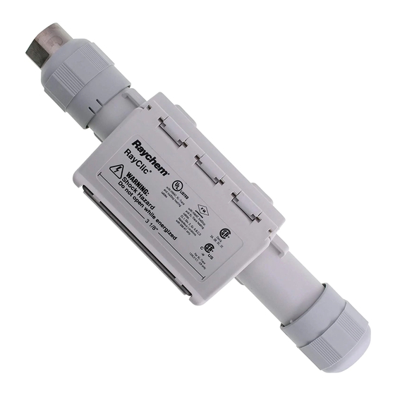
RayClic-PC Power Connection Kit
Item Qty Description
A
1
Power connection
B
1
Pipe mounting bracket
C
2
Plastic cable ties
G
1
Cable lubricant
RayClic-PS Powered Splice Kit
Item Qty Description
A
1
Powered splice
B
1
Pipe mounting bracket
C
2
Plastic cable ties
G
1
Cable lubricant
RayClic-PT Powered Tee Kit
Item Qty Description
A
1
Powered splice
B
1
Pipe mounting bracket
C
2
Plastic cable ties
G
1
Cable lubricant
This component is an electrical device that must be
installed correctly to ensure proper operation and to
prevent shock or fire. Read these important warnings
and carefully follow all the installation instructions.
• To minimize the danger of fire from sustained electrical
arcing if the heating cable is damaged or improperly
installed, and to comply with the requirements of Tyco
Thermal Controls, agency certifications, and national
Item Qty Description
D
1
Clip
E
1
End seal
F
4
Labels
(1 HWAT, 1 De-Icing &
Snow Melting, 2 Warning)
Item Qty Description
D
2
Clips
E
2
End seals
F
4
Labels
(1 HWAT, 1 De-Icing &
Snow Melting, 2 Warning)
Item Qty Description
D
3
Clips
E
3
End seals
F
4
Labels
(1 HWAT, 1 De-Icing &
Snow Melting, 2 Warning)
electrical codes, ground-fault equipment protection
must be used. Arcing may not be stopped by conven-
tional circuit breakers.
• Bus wires will short if they contact each other. Keep
bus wires separated.
• Keep components and heating cable ends dry before
and during installation.
RayClic Connection System
RayClic-PC Power Connection and End Seal Kit
RayClic-PS Powered Splice and End Seal Kit
RayClic-PT Powered Tee and End Seal Kit
Installation Instructions
Description
These kits are for use with Raychem IceStop, XL-Trace and HWAT heating
cables. The connection is designed to be strapped to the pipe or mounted
on the wall at the start of the heating cable circuit. These installation
instructions should be used in conjunction with the IceStop, XL-Trace
and HWAT System Installation and Operation Manuals. For technical
support, contact your Tyco Thermal Controls representative or call Tyco
Thermal Controls (800) 545-6258.
Tools Required
• Utility knife
• TORX
T20 screw driver
®
Additional UL Listed or CSA Certified materials required:
• 1/2-inch conduit and fittings
Optional Accessories (not included in this kit):
• RayClic-SB-02 Wall mounting bracket
Approvals
718K Pipe Heating Cable
877Z De-Icing and Snow Melting
Not UL Listed with XL-Trace
heating cable for buried piping.
For HWAT, IceStop, and XL-Trace only
Hazardous Locations: For IceStop (GM-XT) only
APPROVED
Class I, Div. 2, Groups A,B,C,D
A
B
A
B
A
B
A
B
A
B
A
B
A
B
A
B
A
B
• The black heating cable core is conductive and can
short. It must be properly insulated and kept dry.
• Component approvals and performance are based on
the use of Tyco Thermal Controls-specified parts only.
Do not use substitute parts or vinyl electrical tape.
• Leave these instructions with end user for reference
and future use.
• Wire cutters
• Wrenches (2)
• Junction box
-w
C
D
E
F
C
D
E
F
C
D
E
F
C
D
E
F
C
D
E
F
C
D
E
F
C
D
E
F
C
D
E
F
C
D
E
F
G
G
G
G
G
G
G
G
G
Advertisement

Subscribe to Our Youtube Channel
Related Manuals for Raychem RayClic-PC


Summary of Contents for Raychem RayClic-PC
- Page 1 Installation Instructions Description These kits are for use with Raychem IceStop, XL-Trace and HWAT heating cables. The connection is designed to be strapped to the pipe or mounted on the wall at the start of the heating cable circuit. These installation instructions should be used in conjunction with the IceStop, XL-Trace and HWAT System Installation and Operation Manuals.
- Page 2 • Using the plastic cable ties, attach* the bracket to the pipe. * For roof-mounted applications, • For the RayClic-PC power connection, fold up the four outer snaps, follow steps 3 through 9 (pages 2–4), then position the connector over the snaps and press down.
- Page 3 RayClic-PC, RayClic-PS, RayClic-PT Installation Instructions HWAT IceStop and XL-Trace IceStop and XL-Trace Only HWAT Only 1" • Using wire cutters, cut away 1-inch of the braid. • Pull exposed braid back over metal clip. • Pull exposed braid back over metal clip.
-
Page 4: Power Connection
RayClic-PC, RayClic-PS, RayClic-PT Installation Instructions Tighten the screws until the metal top surface is at the same height as the inner clear plastic module. • Securely tighten the two connection screws, alternating as they are being tightened. • For Powered Splice and Tee kits, repeat steps 3 through 8 for all •... -
Page 5: Roof Installation
RayClic-PC, RayClic-PS, RayClic-PT Installation Instructions Roof Installation RayClic-SB-02 RayClic-PS RayClic-PC and RayClic-PT • Mount flat (wall mounting) bracket under eaves by installing screws • Position attachment clips on mounting bracket based on the type of through the center holes. the connector being installed. - Page 6 RayClic-PC, RayClic-PS, RayClic-PT Installation Instructions End Seal Installation 1" • Score around and down the outer jacket 1-inch from the end. • Remove the outer jacket. • Remove exposed braid. • Do not cut or damage the inner jacket. IceStop and XL-Trace...
-
Page 7: Troubleshooting Guide
Fold up only the center clips for the Powered Splice and Powered Tee kits. Heating cable type not mentioned. RayClic connection kits are approved for use only with Raychem HWAT, XL-Trace, and IceStop heat- ing cables. Do not use with other heating cables. - Page 8 Heating Cable Circuit Testing The RayClic Power Connection Kits (RayClic-PC, RayClic-PS and RayClic-PT) now include test ports in the blank module. Voltage can measured at these points to confirm continuity or power to the installed heating cable circuit. For detail heating cable operation refer to the appropriate installation and operating manual.
Need help?
Do you have a question about the RayClic-PC and is the answer not in the manual?
Questions and answers
How can I tell what voltage?
The voltage rating for Raychem part number RayClic-PC is not provided in the given context.
This answer is automatically generated