Table of Contents
Advertisement
WEB/CP-202-XPR and
WEB/CP-602-XPR Controllers
This document covers the mounting and wiring of the WEB/CP-202-XPR and WEB/CP-602-XP
controllers. It assumes that you are an engineer, technician, or service person who is performing
control system installation. Instructions in this document apply to the following products:
Model
Base unit including two Ethernet ports, one RS-232 port, one
a
WEB/CP-202-XPR
RS-485 port, integral power supply for 24Vac/dc input, and
b
WEB/CP-602-XPR
16 onboard I/O points (8 universal inputs, 4 digital outputs,
4 analog outputs).
a
WEB/CP-202-XPR or WEB/CP-602-XPR with a factory
WEB/CP-202-XPR-GW
installed wireless GPRS modem module and a SIM card for
b
WEB/CP-602-XPR-GW
use on the Wyless Network.
a
WEB/CP-202-XPR models: PowerPC
128MB SDRAM
b
WEB/CP-602-XPR models: PowerPC 440 processor @ 524 MHz, 128MB Flash,
256MB DDR RAM
NOTE: Not covered in this document is the Niagara
Refer to the JACE NiagaraAX Install and Startup Guide, GPRS Modem Option - Engineering Notes, and NiagaraAX
NRIO Guide documents for this information
.
These are the main sections in this document:
Product Description ......................................... 2
Preparation ....................................................... 4
Precautions ...................................................... 5
Mounting ........................................................... 6
Board Layout ................................................... 11
About Expansion Options ............................. 12
Wiring Summary ............................................ 13
Earth Ground and 24V Input Power ............. 14
I/O Wiring ........................................................ 15
External 12V Backup Battery ........................ 22
Wiring to Remote I/O Modules ...................... 23
Power Up and Initial Checkout ..................... 23
Description
®
405EP processor @250 MHz, 64MB Flash,
AX
™ software installation and configuration required for a functioning unit.
Also included in this document are several appendixes:
About LEDs ........................................................................ 25
Controllers ......................................................................... 27
Replacement Parts ............................................................ 28
Controller ........................................................................... 29
Returning a Defective Unit ................................................ 31
Certifications ...................................................................... 32
INSTALLATION INSTRUCTIONS
M29982
95-7775-01
Advertisement
Table of Contents

Related Manuals for Honeywell WEB/CP-202-XPR


Summary of Contents for Honeywell WEB/CP-202-XPR
-
Page 1: Table Of Contents
WEB/CP-602-XPR Controllers INSTALLATION INSTRUCTIONS This document covers the mounting and wiring of the WEB/CP-202-XPR and WEB/CP-602-XP controllers. It assumes that you are an engineer, technician, or service person who is performing control system installation. Instructions in this document apply to the following products:... -
Page 2: Product Description
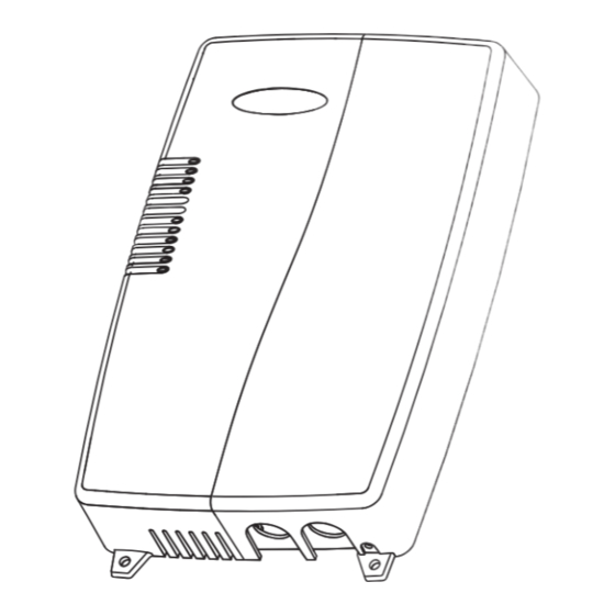
Packaging and Features The WEB/CP-202-XPR and WEB/CP-602-XPR have a plastic chassis designed for wall mounting by using three (3) screws; one in a rear keyhole slot, and two into lower mounting tabs. Vents at the top and bottom of the unit allow cooling by air convection. - Page 3 • One (1) isolated RS-485 / 15 Vdc power on a 6-position connector. Usable as a standard non-powered isolated RS-485 port on 3 terminals, or to support remote I/O modules – available in a later release. (A maximum of three IO-16-REM-H modules on the WEB/CP-202-XPR controller is recommended, due to platform resource considerations).
-
Page 4: Preparation
— One (1) 2-position screw terminal block for external 12V sealed lead-acid battery (not provided). — A GSM/GPRS coax-mounted stub antenna (for units ordered with integral GPRS modem). • If a WEB/CP-202-XPR-GW or WEB/CP-602-XPR-GW model controller, a SIM card provisioned by the Wyless Group. 95-7775—01... -
Page 5: Precautions
WEB/CP-202-XPR AND WEB/CP-602-XPR CONTROLLERS Material and Tools Required The following supplies and tools are typically required for installation: • Suitable tools and fasteners for mounting unit and accessories. — #1 Phillips screwdriver used to remove and replace cover screws. — #2 Phillips screwdriver used to install optional communications card. -
Page 6: Mounting
WEB/CP-202-XPR AND WEB/CP-602-XPR CONTROLLERS NiMH Battery Precautions Observe the following NiMH (Nickel Metal Hydride) battery precautions: WARNING Overcharging, short-circuiting, reverse charging, mutilation, or incineration of the cells and the batteries must be avoided to prevent one or more of the following occurrences: Release of toxic materials, release of hydrogen and/or oxygen gas, rise in surface temperature. - Page 7 M29987 0.225 (5.7) Fig. 2. WEB/CP-202-XPR or WEB/CP-602-XPR controller wall mounting dimensions in inches (mm) and details. To mount unit on wall. 1. For the rear center keyhole slot, install a pan head screw into the wall (1a in Fig. 2). Do not tighten completely. Leave the back of the screw head about 3/32 in.
- Page 8 WEB/CP-202-XPR AND WEB/CP-602-XPR CONTROLLERS Removing and Replacing the Covers The controller has two plastic covers, each is secured by two #1 phillips head screws: • Right cover — Must be removed first, provides access to all wiring terminals (controller and I/O wiring).
- Page 9 Locate and remove chassis knockouts The WEB/CP-202-XPR or WEB/CP-602-XPR has six (6) wiring knockouts on the back of the plastic chassis (see Fig. 4): • Five (5) round, 0.945 in. (24 mm) diameter, for general wiring of controller terminals and I/O points.
- Page 10 SIM CARD SOCKET M28867 Fig. 5. Inserting SIM in the WEB/CP-202-XPR-GW or WEB/CP-602-XPR-GW SIM card socket, attaching antenna (GPRS factory equipped units only). NOTE: The lower antenna jack is for the integral GPRS modem, where the antenna attaches using a standard SMA coax connector.
-
Page 11: Board Layout
FOR EXTERNAL 12V BACKUP BATTERY EARTH GROUND AND 24 VAC OR VDC INPUT SEE EARTH GROUND AND 24V INPUT POWER ON PAGE 14. LED COLORS: = GREEN, = YELLOW. NIMH BATTERY PACK M28868 Fig. 6. WEB/CP-202-XPR and WEB/CP-602-XPR main board layout details. 95-7775—01... -
Page 12: About Expansion Options
Power to the controller must be OFF, and all LEDs out, when installing or removing an option card, or else damage will occur! Be sure to properly align pins when plugging an option card into the connector. Table 1 lists the supported models of communications option cards for a WEB/CP-202-XPR or WEB/CP-602-XPR controller. Table 1. T-x02-XPR-24 option cards. -
Page 13: Wiring Summary
About Remote I/O Modules The WEB/CP-202-XPR and WEB/CP-602-XPR have an integral 6-pin connector to support remote I/O modules. The connector provides both 15 Vdc power and RS-485 communications to modules on that connected trunk, and is located below the 6- position Digital Output (DO) I/O connector (see Fig. -
Page 14: Earth Ground And 24V Input Power
WEB/CP-202-XPR AND WEB/CP-602-XPR CONTROLLERS EARTH GROUND AND 24V INPUT POWER After mounting the unit, wire earth ground and 24 Vac or 24 Vdc to the terminals under the power input shield. NOTE: If powering from a 24V transformer, do not power any other equipment with it. Otherwise, conducted noise problems may result. -
Page 15: I/O Wiring
EARTH GROUND TERMINAL STRIP (FOR CABLE SHIELD WIRE TERMINATIONS) M28870 Fig. 8. Input and Output terminal locations on the WEB/CP-202-XPR and WEB/CP-602-XPR controllers. Inputs Each of the 8 universal inputs (UI) can support any one of the following: • Thermistor Type-3 10K ohm (also see CAUTION on page 16) •... - Page 16 WEB/CP-202-XPR AND WEB/CP-602-XPR CONTROLLERS USE POINT: ThermistorInputPoint SHIELD CUT AND TAPE SHIELD WIRE BACK AT THERMISTOR 10K THERMISTOR SHIELDED, TWISTED CABLE, 200 FEET (61 M) MAXIMUM M28871 Fig. 9. Thermistor sensor wiring diagram. Resistive 0 to 100K ohms Inputs can read a resistive signal within a range from 0 to 100,000 ohms. Wiring is the same as shown for a Thermistor temperature sensor (Fig.
- Page 17 WEB/CP-202-XPR AND WEB/CP-602-XPR CONTROLLERS SHIELD CUT AND TAPE SHIELD WIRE BACK AT SENSOR – 4 TO 20 mA SENSOR (SELF POWERED) RANGE: 4 TO 20 mA SHIELDED, TWISTED CABLE, 200 FEET (61 M) MAXIMUM 499 OHM RESISTOR (SUPPLIED WITH UNIT)
- Page 18 WEB/CP-202-XPR AND WEB/CP-602-XPR CONTROLLERS SHIELD USE POINT: CounterInputPoint CUT AND TAPE SHIELD WIRE BACK AT DEVICE PULSE RANGE: 20 Hz, 50% DUTY CYCLE MINIMUM DWELL TIME: > 25 ms SHIELDED, TWISTED CABLE, 200 FEET (61 M) MAXIMUM SHIELD USE POINT: BooleanInputPoint...
-
Page 19: Nrio16Module (Software) Representation
Nrio16Module (Software) Representation In the Niagara station interface to the WEB/CP-202-XPR or WEB/CP-602-XPR, the controller’s onboard I/O is modeled in the station’s M2mIoNetwork (copied from the nrio palette), under a child Nrio16Module “device level” component. This Nrio16Module has a default name of “LocalIo16”. - Page 20 WEB/CP-202-XPR AND WEB/CP-602-XPR CONTROLLERS For both local and remote I/O, each input or output used requires a special Niagara Remote Input/Output (Nrio) point to be added in the station database. These components act as the station interface to the physical I/O points. The Nrio points you need for each input or output type are noted in previous wiring sections in boldface.
- Page 21 WEB/CP-202-XPR AND WEB/CP-602-XPR CONTROLLERS NOTES: 1. An additional serial port may be added with an option card in Option Slot 1, such as an NPB-RS232 card (port oper- ates as COM7) or NPB-2X-RS485 card—note this option actually adds two serial ports, which operate in the control- ler as COM7 and COM8.
-
Page 22: External 12V Backup Battery
• 16AWG (1.29mm) for up to 12 ft. (3.66m). – 15 VDC POWER AND BACKUP BATTERY PASSED THROUGH 6-POSITION CONNECTOR. – RS-485 RS-485 485 GND – 712BNP 12V SEALED LEAD ACID BACKUP BATTERY(IES) M28879 Fig. 16. Sealed lead-acid backup battery connection on the WEB/CP-202-XPR or WEB/CP-602-XPR. 95-7775—01... -
Page 23: Wiring To Remote I/O Modules
WEB/CP-202-XPR, DUE TO PLATFORM RESOURCE CONSIDERATIONS. M28880 Fig. 17. RS-485 cabling between WEB/CP-202-XPR and WEB/CP-602-XPR and remote I/O modules. For related information, see the IO-16-REM-H Installation and Configuration Instructions document. POWER UP AND INITIAL CHECKOUT Following all mounting and wiring (I/O Wiring, Communications Wiring, External 12V Backup Battery, Wiring to Remote I/O... - Page 24 Apply Power The WEB/CP-202-XPR and WEB/CP-602-XPR controllers do not include an on/off switch. To apply power, you simply energize the 24 Vac transformer (or 24 Vdc power supply) wired to the 3-position power input terminals. If remote I/O modules are wired to the unit, they are also typically powered by the controller as well.
-
Page 25: About Leds
Replace the sealed lead-acid backup batteries approximately every three (3) years, or more often if the unit is in a high temperature environment. ABOUT LEDS The WEB/CP-202-XPR and WEB/CP-602-XPR provide a number of LEDs, most of which are visible on the left cover. Fig. 18 shows LED locations, along with following descriptions. STATUS... - Page 26 WEB/CP-202-XPR AND WEB/CP-602-XPR CONTROLLERS Beat The yellow heartbeat BEAT LED is located on the cover. Following boot-up, the heartbeat LED blinks about once per second. If the heartbeat LED stays on constantly, does not light, or blinks very fast (more than once per second), contact System Engineering for technical support.
-
Page 27: Maintaining The Web/Cp-202-Xpr And Web/Cp-602-Xpr Controllers
(see Fig. 19 on page 28). To replace the battery, you must remove power to the unit and remove both covers. CAUTION Use only NiMH battery packs approved for use with the WEB/CP-202-XPR and WEB/CP-602-XPR controllers. Replacing NiMH battery assembly in a WEB/CP-202-XPR or WEB/CP-602-XPR. -
Page 28: Replacement Parts
NiMH battery pack to Tridium for proper disposal. REPLACEMENT PARTS Servicing the WEB/CP-202-XPR or WEB/CP-602-XPR may call for replacement parts. There are three categories of parts: • Non-replaceable Parts • Standard Replacement Parts • New Replacement Unit... -
Page 29: Replacing The Web/Cp-202-Xpr Or Web/Cp-602-Xpr Controller
New Replacement Unit To replace an entire unit, order and install a new WEB/CP-202-XPR or WEB/CP-602-XPR. If the faulty controller is still in warranty, you may receive credit by returning it to Tridium. Contact Tridium for a return authorization (RMA) number before shipping any item for return credit. - Page 30 WEB/CP-202-XPR AND WEB/CP-602-XPR CONTROLLERS NOTE: Typically, if I/O wiring is routed through rear knockouts, you must remove it from the controller’s screw terminal blocks, so that the wiring can pass through the knockouts. In this case, it is extremely important to remove all related power sources, in order to prevent electrical shock and equipment damage.
-
Page 31: Returning A Defective Unit
WEB/CP-202-XPR AND WEB/CP-602-XPR CONTROLLERS RETURNING A DEFECTIVE UNIT NOTE: If the defective unit is under warranty, please follow return instructions provided in this section. If the unit is out of warranty, please discard any replaced part. • Do not return an out-of-warranty controller to Tridium. -
Page 32: Certifications
WEB/CP-202-XPR AND WEB/CP-602-XPR CONTROLLERS CERTIFICATIONS Federal Communications Commission (FCC) This equipment generates, uses, and can radiate radio frequency energy, and if not installed and used in accordance with the instruction manual, may cause interference with radio communications. It has been tested and found to comply with the limits for a Class A computing device pursuant to Subpart J of Part 15 of FCC Rules, which are designed to provide reasonable protection against such interference when operated in a commercial environment.
Need help?
Do you have a question about the WEB/CP-202-XPR and is the answer not in the manual?
Questions and answers