Table of Contents
Advertisement
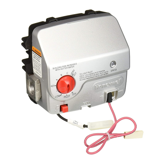
WV8840A Water Heater Controls
APPLICATION
The WV8840A Water Heater Control is designed for use
in Standing Pilot applications using an immersion well for
water temperature sensing. All models of WV8840A
include an integrated NTC temperature sensor.
The WV8840A is powered from a thermopile heated by
the standing pilot flame. CS8840 pilot assemblies are
designed for use with this control.
The immersion well for sensing water temperature has
matched NTC thermistor sensors. These sensors
provide the fail-safe mechanism through which the
WV8840A can provide both accurate water temperature
control as well as water temperature limit (Temperature
Cut-Out [TCO]) function.
SPECIFICATIONS
IMPORTANT
WV8840A controls provide direct replacement
only.
Pressure Regulator: The outlet pressure regulator
setting is shown on the product label.
Inlet Pressure Range:
See appliance rating plate for inlet pressure range
recommendation.
1/2 PSI (14.0 in. w.c.) maximum inlet pressure allowed
for proper operation.
Body Pattern: 90 degrees with 1/2 in. inlet and 1/2 in.
inverted flare outlet.
Mounting: Mounting in upright position only.
Installation INSTRUCTIONS
Control Input:
Voltage Minimum: 350 mV dc, open circuit.
Voltage Maximum: 850 mV dc, open circuit.
Capacity: See Table 1.
Regulation Range:
Natural Gas:
Minimum: 30,000 Btuh.
Maximum: 85,000 Btuh.
Ambient Temperature Range: 32°F to 150°F
(0°C to 66°C)
Operating Range: 0°F to 150°F (-18°C to 66°C)*
Storage Range: -40°F to 150°F (-40°C to 66°C)
* Valve will operate at 0°F (-18°C) but valve characteris-
tics can not be guaranteed until ambient temperature
reaches 32°F (0°C).
Humidity: 95% non-condensing at 104°F (40°C)
Approvals:
This device is certified by Canadian Standards Associa-
tion (CSA) to the following standards:
ANSI Z21.20
ANSI Z21.23
ANSI Z21.78
ANSI Z21.87
CAN/CSA-C22.2 No. 199-M89
CAN1-6.6-M78
CSA 4.6
CSA 6.20
Accessory Parts:
Pilot Assembly CS8840
69-2247-05
Advertisement
Table of Contents
Troubleshooting

Related Manuals for Honeywell WV8840A


Summary of Contents for Honeywell WV8840A
- Page 1 WV8840A Water Heater Controls INSTALLATION INSTRUCTIONS APPLICATION The WV8840A Water Heater Control is designed for use Control Input: in Standing Pilot applications using an immersion well for Voltage Minimum: 350 mV dc, open circuit. water temperature sensing. All models of WV8840A Voltage Maximum: 850 mV dc, open circuit.
- Page 2 Dripping water can cause the control to fail. Never install M29520 an appliance where water can drip on the control. In Fig. 1. Typical capacity curve for WV8840A family addition, high ambient humidity can cause the control to water heater control system.
- Page 3 Always use a direct replacement sensor assembly DROP TUBING when replacing a temperature sensor. HORIZONTAL SUPPLY Location The WV8840A is mounted on the outside of the water heater tank. See Fig. 2. RISER 3 IN. (76 MM) MOUNTING MINIMUM WARNING...
- Page 4 WV8840A WATER HEATER CONTROLS Wiring IGNITION Follow the wiring instructions furnished by the appliance IMPERFECT SYSTEM THREADS CONTROL manufacturer, if available, or use the general instructions provided below. When these instructions differ from the appliance manufacturer, follow the appliance PIPE manufacturer instructions.
- Page 5 Can damage electrical components in the WV8840A. Do not spray soap and water solution on the WARNING WV8840A housing. Do not use an excessive amount of soap and water to perform the gas leak Fire or Explosion Hazard. Can cause severe test.
- Page 6 WV8840A WATER HEATER CONTROLS 3. After status indicator analysis and appliance repair tank should turn on the main burner. The Status is complete, turn device knob to OFF, wait until the indicator light will strobe every three seconds when indicator goes out, then perform lighting procedure.
- Page 7 WV8840A WATER HEATER CONTROLS Troubleshooting Without Status Indicator Assistance Follow diagram in Fig. 6. TROUBLESHOOTING GUIDE WITHOUT STATUS LIGHT TURN DEVICE KNOB FROM OFF TO CHECK: PILOT, PRESS DOWN KNOB AND HOLD, • INLET PRESSURE LIGHT PILOT BY DEPRESSING PIEZO •...
- Page 8 WV8840A WATER HEATER CONTROLS TURNING OFF THE IMPORTANT Follow the operating instructions provided by APPLIANCE the manufacturer of your water tank appliance. The information in this form describes a typical water heater control application, but the specific Complete Shutdown controls used and the procedures outlined by the manufacturer of your appliance can differ, 1.
Need help?
Do you have a question about the WV8840A and is the answer not in the manual?
Questions and answers
My water heater goes to 5 red flashes, which is listed as temperature sensor fault. The diagrams in this Manuel do not show anything that is a temperature sensor. Is it a seperate part or is it internal to the controller? I **** able to do a reset and it works for another few days, then temperature sensor fault again.
The temperature sensor for the Honeywell WV8840A water heater is internal to the controller. It includes an integrated NTC temperature sensor.
This answer is automatically generated
Thank you for the response. Looks like this means replace the whole controller if it wont reset. For now it only fails once every few months, and resets just fine.
why is the Honeywell control beeping??? WV8840B1158?
The Honeywell WV8840A control may beep due to issues such as high humidity, dripping water, or exposure to corrosive chemicals, which can cause the control to fail. It may also beep if the appliance does not turn on due to problems with the gas supply or if the thermopile needs time to cool before relighting the pilot.
This answer is automatically generated