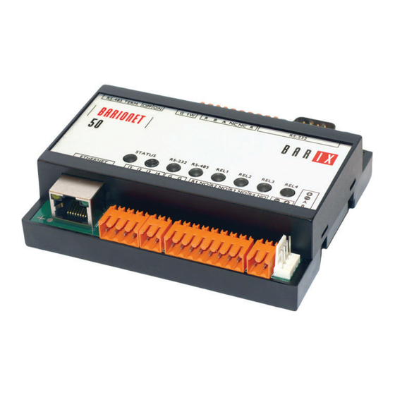
Aiphone RY-IP44 User Programming Manual
Input/output network adaptor for use with ix series, is-ip series, and ipw-1a
Hide thumbs
Also See for RY-IP44:
- Programming manual (12 pages) ,
- Programming manual (4 pages) ,
- Programming manual (15 pages)
Table of Contents
Advertisement
Quick Links
Download this manual
See also:
Programming Manual
0517
#95101
RY-IP44
Input/Output Network Adaptor
Programming Manual
For use with IX Series, IS-IP Series, and IPW-1A
ATTENTION:
This is the programming manual for the RY-IP44 only. Refer to the Installation and Setting
Manuals for the series being integrated with for complete installation/programming information
on each system (IX, IS-IP, IPW-1A).
Advertisement
Table of Contents

Summary of Contents for Aiphone RY-IP44
- Page 1 For use with IX Series, IS-IP Series, and IPW-1A ATTENTION: This is the programming manual for the RY-IP44 only. Refer to the Installation and Setting Manuals for the series being integrated with for complete installation/programming information on each system (IX, IS-IP, IPW-1A).
-
Page 2: Package Contents
Mobile devices and will alert the mobile device if it goes out of wireless network range. If only using the RY-IP44 for IX Mobile, configure the adaptor as shown on page 5, then skip to page 11 (IX Mobile Server). The SIF.ini file is not needed when only using the adaptor for IX Mobile. Refer to pages 11-15 for steps on adding a mobile device to the IX Series using the IX Support Tool and for setting up the mobile device. - Page 3 C. Choose the station to be edited from the Number drop down menu, then click the Select button. NOTE: When using the RY-IP44 for door release, the SIF.ini file must be uploaded to the door station. D. Select the Enable radio button for both the CGI Integration and SIF Integration.
- Page 4 RY-IP44 IS-IP Series: Uploading SIF.ini File Upload the SIF.ini file to each IS-IP Series station associated with the RY-IP44 adaptor. ! Note that the IP address for each station will be unique for your network settings. Important: The intercom system should be fully programmed and operational prior to uploading the SIF.ini file.
- Page 5 SIF.ini file. The Aiphone system type that the adaptor is being integrated with will need to be selected. Click the AIPHONE tab. Use the drop down by System Type to select the appropriate system. Enter the SIF Socket Local Port number that was assigned in the SIF.ini file (Destination Port).
- Page 6 • Active during Calling and Communicating When the relay action is set for one of the “Door Release” options, the relay on the RY-IP44 will trigger when the associated station’s door release contact is triggered. When the relay action is set for any of the “Active While” options, the relay will trigger when the associated station calls or communicates at any priority level.
- Page 7 Note: The RY-IP44 inputs can have different calling rules than the default calling rule set for a station during the IX Series programming. Select the call-in priority level for each input using the Priority drop down menu.
-
Page 8: Relay Functionality
Linked Stations Table: Enter the IP address and TermID for each IS-IP station in the IS configuration. This table is used as a reference for each station in the system that will be able to communicate with the RY-IP44 adaptor. Definition: TermID A TermID identifies the location of an IS-IP station in the IS Series configuration. -
Page 9: Input Programming
Input Programming The RY-IP44 adaptor has 4 inputs that can be programmed to trigger a call-in from a specific door station to a specific master station or group of master stations (max. 20). The RY-IP44 inputs can have different calling rules than the default calling rule set under Advanced Station Settings in the IS Host Programming. - Page 10 Relay triggers when any station calls. No assignment required. * When using the RY-IP44 for door release, the relay on the IPW-1A must be set to door release and the relay must be jumpered to the sensor input as shown below.
- Page 11 Enter the Station ID for the IPW-1A to be associated with each relay on the RY-IP44. Select the relay condition from the Relay Action drop down menu. When done, click on Apply Settings. Click Reboot on the next screen to restart the adaptor with the applied settings.
- Page 12 Individual Master Station Door Release Settings button. Select the newly added mobile master from the drop down. Click Select. To enable door release for all stations for this selected master station, click the Apply button. 12 | RY-IP44 Programming Manual...
-
Page 13: Configuration File
OK. Another pop-up will • A pop-up will appear saying “All stations will be set for door release. Continue?” Click appear saying “Door release settings complete.” Click Repeat the process for each mobile master station added to the system. File, then Upload Settings To Station. - Page 14 Default ID: admin Default Password: admin Tap App Server. Enter the IP Address and Port Number for the App Server (RY-IP44). Refer to page 11 for information on setting up the App Server. Tap Import from File. Select the configuration file that was transferred to this device in Step 3.
- Page 15 Default ID: admin Default Password: admin Tap App Server. Enter the IP Address and Port Number for the App Server (RY-IP44). Refer to page11 for information on setting up the App Server. Tap Import from File. Select the configuration file that was transferred to this device in Step 5.
- Page 16 RY-IP44 Dimensions Mounting: The RY-IP44 adaptor mounts to an Aiphone Depth: W-DIN11 mounting rail (sold separately). 1-1/4” 4-1/8” RY-IP44 Wiring Power Transformer (use proper power for the strike, mag lock, or external signaling device being used). Relay contact rating: 30V DC, 0.5A.


Need help?
Do you have a question about the RY-IP44 and is the answer not in the manual?
Questions and answers