Table of Contents
Advertisement
Quick Links
Swing Piston Compressors and Vacuum Pumps
Operating and
Installation
Instructions
Read and observe these Oper-
ating and Installation Instruc-
tions!
KNF Neuberger GmbH
Alter Weg 3
D-79112 Freiburg
Germany
Tel. +49-(0)7664-5909-0
Fax +49-(0)7664-5909-99
E-Mail: info@knf.de
www.knf.de
KNF 121581-121584 08/16
Translation of original Operating and Installation Instructions, english
NPK 25 AC
NPK 25 DC
Contents
1. About this document ................................................................. 2
2. Use ........................................................................................... 3
3. Safety ....................................................................................... 4
4. Technical data .......................................................................... 6
5. Design and function .................................................................. 7
6. Installation and connection ....................................................... 8
7. Operation ................................................................................ 12
8. Servicing ................................................................................. 13
9. Troubleshooting ...................................................................... 16
10. Spare parts and accessories .................................................. 18
11. Returns ................................................................................... 19
Page
Keep for future use!
Advertisement
Table of Contents

Related Manuals for KNF NPK 25 AC


Summary of Contents for KNF NPK 25 AC
-
Page 1: Table Of Contents
Swing Piston Compressors and Vacuum Pumps NPK 25 AC NPK 25 DC Operating and Installation Instructions Read and observe these Oper- ating and Installation Instruc- tions! Contents Page 1. About this document ..............2 2. Use ................... 3 KNF Neuberger GmbH 3. -
Page 2: About This Document
An activity to be carried out (a step) is specified here. 1. The first step of an activity to be carried out is specified here. Additional, consecutively numbered steps follow. This symbol refers to important information. Translation of original Operating and Installation Instructions, english, KNF 121581-121584 08/16... -
Page 3: Use
The pumps may not be operated in an explosive atmosphere. The pumps may not be used to pump combustible or potentially explosive media. The pumps are not suitable for pumping vapors or liquids. Translation of original Operating and Installation Instructions, english, KNF 121581-121584 08/16... -
Page 4: Safety
In addition a protection against mechanical parts in motion and hot parts, if existing, has to be provided when mounting. Translation of original Operating and Installation Instructions, english, KNF 121581-121584 08/16... - Page 5 DIN EN 60335-1 DIN EN 50581 DIN EN 50581 Tab. 2 Customer service and repairs Only have repairs to the pump carried out by the KNF Customer Service responsible. Translation of original Operating and Installation Instructions, english, KNF 121581-121584 08/16...
-
Page 6: Technical Data
+ 5 °C to + 40 °C Gas-tightness The gas-tightness of the pump is dependent on the medium used.* * If you have questions about this, please contact your KNF advisor. Tab. 7 Translation of original Operating and Installation Instructions, english, KNF 121581-121584 08/16... -
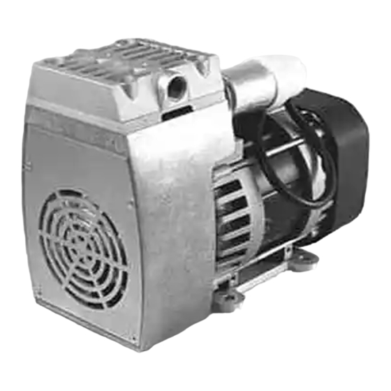
Page 7: Design And Function
Design and function Design Pneumatical outlet Pneumatical inlet Front fan cover Pump housing Base plate Motor Fig. 1: Swing piston compressor and vacuum pump NPK 25 AC Function Inlet valve Outlet valve Transfer chamber Retainer plate Piston seal Eccentric Connecting rod Compressor housing Fig. -
Page 8: Installation And Connection
6.1. Installation Before installation, store the pump at the installation location to bring it up to room temperature. For the mounting dimensions see fig. 3 (NPK 25 AC) or fig. 4 Mounting dimensions (NPK 25 DC) Fig. 3: Mounting dimensions NPK 25 AC... - Page 9 60335-1) must be made for disconnecting the pump motor from the electrical supply. For pumps with AC motors KNF recommends that a fuse is installed in the motor supply circuit (overcurrent release). For operating current see type plate or data sheet.
- Page 10 (usual) A.C. / D.C. converter. The test is applicable for D C power inputs which are foreseen for a permanent connection to cables which are longer than 10 m. Translation of original Operating and Installation Instructions, english, KNF 121581-121584 08/16...
- Page 11 Connect the suction line and pressure line (threadsize G ¼``). Lay the suction and pressure line at a downward angle to prevent condensate from running into the pump. Translation of original Operating and Installation Instructions, english, KNF 121581-121584 08/16...
-
Page 12: Operation
The pump may not start up against pressure or vacuum during switch-on. This also applies in operation following a brief power failure. Make sure that normal atmospheric pressure is present in the lines during switch-on. Translation of original Operating and Installation Instructions, english, KNF 121581-121584 08/16... -
Page 13: Servicing
Quantity Tools/Material Phillips screwdriver No. 1 (only for pump NPK 25 DC) Phillips screwdriver No. 2 Screwdriver blade width 5.5 mm Allen key 4 mm Felt-tip pen Tab. 10 Translation of original Operating and Installation Instructions, english, KNF 121581-121584 08/16... - Page 14 Push the new countersunk screw (7) with new O-ring (8) through the retainer plate (9). 4. Fit the same number of washer(s) (11) as previously used on connecting rod (14). Translation of original Operating and Installation Instructions, english, KNF 121581-121584 08/16...
- Page 15 12. Tighten the screws (1) at first lightly, then firmly by hand, in a diagonal pattern (max. tightening torque 6.5 Nm). Final step 1. Refit front fan cover. Translation of original Operating and Installation Instructions, english, KNF 121581-121584 08/16...
-
Page 16: Troubleshooting
Eliminate leaks. Leaks occur on connections, lines or pump head. Check connections and lines. Connections or lines completely or partially jammed. Remove the jamming parts and particles. Translation of original Operating and Installation Instructions, english, KNF 121581-121584 08/16... - Page 17 Fault cannot be rectified If you are unable to determine any of the specified causes, send the pump to KNF Customer Service (see last page for the ad- dress). Flush the pump to free the pump head of dangerous gases.
-
Page 18: Spare Parts And Accessories
*according to Fig. 5 Accessories Accessory Order No. Silencer/filter 007007 Hose connector* 000362 Sealing for hose connector 001818 Tab. 14 * requires Sealing for hose connector Order No. 001818 Translation of original Operating and Installation Instructions, english, KNF 121581-121584 08/16... -
Page 19: Returns
For optimal processing of a return, a copy of this declaration should be sent in advance via e-mail, regular mail, or fax to KNF Customer Service (refer to final page for address). In order to avoid endangering employees who open the shipment's packaging,... -
Page 20: Health And Safety Clearance And Decontamination Form
Health and safety clearance and decontamination form Swing Piston Pumps NPK 25 12. Health and safety clearance and decon- tamination form KNF worldwide Find your local KNF partner on www.knf.com...
Need help?
Do you have a question about the NPK 25 AC and is the answer not in the manual?
Questions and answers