Table of Contents
Advertisement
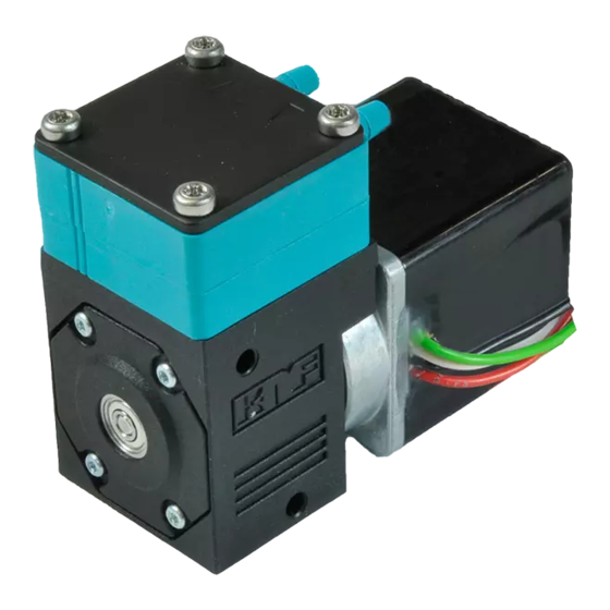
DIAPHRAGM LIQUID PUMP
NF 30, NFB 30
NF 30 KP .51 .27 DC 12V
.51 / - [Ch. 2]
KP / KT / TT / FT [Ch. 4]
30
NF / JNF / NFB
- / PMLxxxx / PLxxxx [Ch. 1]
Operating and
Installation
Instructions
Read and observe these
operating and installation
instructions!
An additional letter prefixing
the NF model code is a
country-specific designation,
with no technical relevance.
KNF Flodos AG
Wassermatte 2
6210 Sursee, Switzerland
Tel. +41 (0)41 925 00 25
Fax +41 (0)41 925 00 35
www.knf-flodos.ch
info@knf-flodos.ch
KNF Flodos AG BA_NF30_EN_05_069206.docx
Translated from the Original Operating and Installation Instructions
Supply voltage [Ch. 4]
E / DC / DCB-B / DCB-4B
.27 / - [Ch. 5]
Contents
1. About this document ................................................................. 2
2. Use ........................................................................................... 3
3. Safety ....................................................................................... 5
4. Technical data .......................................................................... 7
5. Assembly and function ........................................................... 10
6. Installation and connection ..................................................... 11
7. Operation ................................................................................ 18
8. Servicing ................................................................................. 21
9. Troubleshooting ...................................................................... 25
10. Decontamination declaration .................................................. 27
Page
Keep for future reference!
Advertisement
Table of Contents

Subscribe to Our Youtube Channel
Related Manuals for KNF NF 30


Summary of Contents for KNF NF 30
-
Page 1: Table Of Contents
DIAPHRAGM LIQUID PUMP NF 30, NFB 30 NF 30 KP .51 .27 DC 12V Supply voltage [Ch. 4] E / DC / DCB-B / DCB-4B .27 / - [Ch. 5] .51 / - [Ch. 2] KP / KT / TT / FT [Ch. 4] NF / JNF / NFB - / PMLxxxx / PLxxxx [Ch. -
Page 2: About This Document
Diaphragm liquid pump NF 30, NFB 30 About this document About this document 1.1. Use of the operating and installation instructions The operating and installation instructions are part of the pump. ➔ Pass on the operating and installation instructions to the next owner. -
Page 3: Use
Diaphragm liquid pump NF 30, NFB 30 2.1. Proper use The pumps are intended for transferring and metering liquids. Owner's responsibility Only install and operate the pumps under the operating parameters Operating parameters and and conditions described in Chapter 4, Technical data. - Page 4 ➔ Because the cleaning requirements of the diaphragm liquid pumps depend on the application, KNF is unable to guarantee cleaning options. The responsibility for cleaning the pump(s) therefore lies with the user. While the NSF/ANSI 169 standard regulates OEM products, it does not define cleaning methods for specific OEM products.
-
Page 5: Safety
Diaphragm liquid pump NF 30, NFB 30 Safety Safety Note the safety precautions in Chapters 6. Installation and connection, and 7. Operation. The pumps are built according to the generally recognized rules of technology and in accordance with the pertinent occupational safety and accident prevention regulations. - Page 6 IEC/EN 61000-6-3 NF 30 E ▪ EN 55014-1 Customer service and All repairs to the pump(s) must be carried out by the relevant KNF repairs Customer Service team. KNF Flodos AG BA_NF30_EN_05_069206.docx Translated from the Original Operating and Installation Instructions...
-
Page 7: Technical Data
Diaphragm liquid pump NF 30, NFB 30 Technical data Technical data Pump materials The pump type KP stands for: Assembly Material Pump head * Valve plate EPDM Diaphragm EPDM Diaphragm .27 EPDM Tab. 2 according to DIN ISO 1629 and 1043.1... - Page 8 Diaphragm liquid pump NF 30, NFB 30 Technical data Hydraulic ratings Parameter Value 0.3 Flow rate NF 30 [l/min] 1), 2) 2 x 0.3 1), 2) Flow rate NFB 30 [l/min] Permitted pressure [bar above atmospheric] Suction head [mWG] Tab.
- Page 9 Diaphragm liquid pump NF 30, NFB 30 Technical data Specifications 30 E Motor voltage 230V/50Hz Power consumption [W] Max. current at max. load [A] 0.21 Max. motor current [A] 0.22 Protection class [-] IP 00 Weight Tab. 11 The weight may differ slightly from the stated value, depending on the version.
-
Page 10: Assembly And Function
NF 30 version (specified flow rate) This pump type represents this product in its simplest form and delivers media at the specified flow rate. NF 30 .27 version (specified flow rate with overpressure limiting) If the diaphragm liquid pump is operating against a closed system, the delivery pressure quickly exceeds the maximum permissible values. -
Page 11: Installation And Connection
Diaphragm liquid pump NF 30, NFB 30 Installation and connection Installation and connection Only install and operate the pumps under the operating parameters and conditions described in Chapter 4, Technical data. Observe the safety notes (see Chapter 3). 6.1. Installation ➔... - Page 12 Diaphragm liquid pump NF 30, NFB 30 Installation and connection Fig. 5: Mounting dimensions NF 30 DCB-B Fig. 6: Mounting dimensions NF 30 DCB-4B Fig. 7: Mounting dimensions NF 30.27 DCB-B KNF Flodos AG BA_NF30_EN_05_069206.docx Translated from the Original Operating and Installation Instructions...
- Page 13 Diaphragm liquid pump NF 30, NFB 30 Installation and connection Fig. 8: Mounting dimensions NF 30.27 DCB-4B Fig. 9: Mounting dimensions NF 30 E Fig. 10: Mounting dimensions NF 30.27 E KNF Flodos AG BA_NF30_EN_05_069206.docx Translated from the Original Operating and Installation Instructions...
- Page 14 Diaphragm liquid pump NF 30, NFB 30 Installation and connection Fig. 11: Mounting dimensions NFB 30 DCB-B Fig. 12: Mounting dimensions NFB 30 DCB-4B KNF Flodos AG BA_NF30_EN_05_069206.docx Translated from the Original Operating and Installation Instructions...
- Page 15 (Fig. 12). Fig. 13: Optimal mounting orientation / horizontal Decoupling ➔ KNF recommends mechanically decoupling the pump from the pipework system, e.g. by using flexible hoses or pipes. This prevents any oscillations of the pump being transferred to the system.
- Page 16 Diaphragm liquid pump NF 30, NFB 30 Installation and connection Touch and foreign object For pumps with alternating current motors: protection Danger of injury during operation ➔ Take protective measures against touching parts which are energised (live), such as electrical connections or windings.
- Page 17 Diaphragm liquid pump NF 30, NFB 30 Installation and connection 6.3. Hydraulic connection ➔ Only connect components to the pump that are designed to Connected handle the hydraulic data of the pump (see Chapter 4, components Technical data). ➔ Only use hoses that are suitable for the maximum operating Hoses pressure of the pump (see Chapter 4).
-
Page 18: Operation
Diaphragm liquid pump NF 30, NFB 30 Operation Operation ➔ The pumps should only be used under the operating parameters/conditions described in Chapter 4, Technical data. ➔ Ensure that the pumps are being used correctly (see Section 2.1). ➔ Improper use of the pumps must be prevented (see Section 2.2). - Page 19 ➔ Ensure that the system is subject to normal atmospheric pressure (release the hydraulic pressure). Flow rate NF 30 Fig. 15: Flow rate of pumps NF 30 DC and NF 30.27 DC KNF Flodos AG BA_NF30_EN_05_069206.docx Translated from the Original Operating and Installation Instructions...
- Page 20 Fig. 16: Flow rate of pumps NF 30 DCB-B / DCB-4B and NF 30.27 DCB-B / DCB-4B Fig. 17: Flow rate of pumps NF 30 E and NF 30.27 E Flow rate NFB 30 Fig. 18: Flow rate of pump NFB 30 DCB-B / DCB-4B KNF Flodos AG BA_NF30_EN_05_069206.docx...
-
Page 21: Servicing
➔ Rinse the pump with a neutral liquid and pump empty. 8.2.1. Flushing the pump ➔ If pumping aggressive media, KNF recommends flushing the pump with air under atmospheric conditions for several minutes prior to switch off (if necessary for safety reasons: use an inert gas). - Page 22 ➔ The method of assembly will depend on the pump type. For this reason, please proceed with the section that corresponds Fig. 20: NF30.27 to the pump type you are using (NF 30 and NF 30 KP.51 version or NF 30.27 version). Head screw Head plate ➔...
- Page 23 Diaphragm liquid pump NF 30, NFB 30 Servicing NF 30 and NF 30 KP.51 version 1. The visible lines on the intermediate plate (5) and the connecting plate (3) must be in line with each other. 2. The head plate (2) must be positioned so that the flow direction arrows coincide with the connections on the connecting plate (3).
- Page 24 Diaphragm liquid pump NF 30, NFB 30 Servicing 8.4. Adjusting the overflow 1. Test set-up/instrumentation as shown in the diagram. Test set-up for overflow Make sure that the container (a), pump (b), pressure gauge (c) and valve (d) are as level as possible (+/- 15 cm) Fig.
-
Page 25: Troubleshooting
Diaphragm liquid pump NF 30, NFB 30 Troubleshooting Troubleshooting For pumps with alternating current motors: Risk of electric shock, danger of death ➔ Before working on the pump disconnect the pump from the power supply. DANGER ➔ Ensure that the pump is de-energised. - Page 26 Fault cannot be rectified If you are unable to identify any of the above causes, please send the pump to KNF customer services (see address on last page). 1. Flush the pump to clear the pump head of any hazardous or aggressive fluids (see Section 8.2.1).
-
Page 27: 10. Decontamination Declaration
Diaphragm liquid pump NF 30, NFB 30 Decontamination declaration 10. Decontamination declaration KNF shall only undertake to repair the pump on condition that the customer provides certification of the transferred media and the cleaning of the pump (decontamination declaration). ➔ In order to send a product back use the decontamination declaration, which either was delivered with the product or is available on www.knf.com (Downloads). - Page 28 KNF worldwide Please find your local KNF partners at: www.knf.com...
Need help?
Do you have a question about the NF 30 and is the answer not in the manual?
Questions and answers