
Related Manuals for Woods BRUSHBULL BB48X


Summary of Contents for Woods BRUSHBULL BB48X
- Page 1 BRUSHBULL ROTARY CUTTER BB48X BB60X BB72X BB84X Serial Number 1159929 & After Includes Service and Parts Information for Serial Number 1159928 & Prior...
- Page 2 TO THE OWNER: Read this manual before operating your Woods equipment. The information presented will prepare you to do a better and safer job. Keep this manual handy for ready reference. Require all operators to read this manual carefully and become acquainted with all adjustment and operating procedures before attempting to operate.
-
Page 3: Table Of Contents
TABLE OF CONTENTS INTRODUCTION ..........2 SPECIFICATIONS. -
Page 4: Introduction
SPECIFICATIONS 3-Point Hitch: BB48X, BB60X, BB72X ......Category 1 BB84X........Category 1 & 2 Cutting Height . -
Page 5: Safety Video Order Form
Safety Video Order Form BE SAFE! BE ALERT! BE ALIVE! BE TRAINED Before Operating Mowers! Safety Training Does Make a Difference. ASSOCIATION OF EQUIPMENT MANUFACTURERS Watch a Mower Safety Video Online The AEM (Association of Equipment Manufacturers) offers a safety training video, Industrial and Agricultural Mower Safety Practices. - Page 6 Also, available from the Association of Equipment Manufacturers: A large variety of training materials (ideal for groups) are available for a nominal charge from AEM. Following is a partial list: Training Package for Rotary Mowers/Cutters-English ● Contains: DVD & VHS (English) Guidebook for Rotary Mowers/Cutters (English) AEM Industrial/Agricultural Mower Safety Manual (English) AEM Agricultural Tractor Safety Manual (English)
-
Page 7: Safety Rules
SAFETY RULES ATTENTION! BECOME ALERT! YOUR SAFETY IS INVOLVED! Make sure spring-activated locking pin or collar Safety is a primary concern in the design and slides freely and is seated firmly in tractor PTO manufacture of our products. Unfortunately, our spline groove. - Page 8 SAFETY RULES ATTENTION! BECOME ALERT! YOUR SAFETY IS INVOLVED! Before performing any service or maintenance, • If this machine is not equipped with full chain, rubber, or steel band shielding, operation must disconnect driveline from tractor PTO. be stopped when anyone comes within 300 feet (92 m).
- Page 9 SAFETY RULES ATTENTION! BECOME ALERT! YOUR SAFETY IS INVOLVED! STORAGE blocks under cutter side skids. Lower cutter onto blocks. Disconnect cutter from tractor 3-point hitch Keep children and bystanders away from stor- and carefully drive tractor away from cutter. age area.
-
Page 10: Safety Decals
SAFETY & INSTRUCTIONAL DECALS ATTENTION! BECOME ALERT! YOUR SAFETY IS INVOLVED! Replace Immediately If Damaged! 1 - SERIAL NUMBER PLATE 6 – PN 20106 RED REAR REFLECTOR 4.5" 12 - PN 57123 RED REAR REFLECTOR 9" 8 - PN 1006682 DANGER DANGER ROTATING DRIVELINE... - Page 11 FALLING OFF OR FAILING TO BLOCK SECURELY CAN RESULT IN SERIOUS INJURY OR DEATH. Replacement safety decals can be ordered free from your Woods dealer. To locate your WARNING nearest dealer, check the Dealer Locator at www.WoodsEquipment.com, or in the United...
-
Page 12: Operation
OPERATION The operator is responsible for the safe operation of Tractor Stability the cutter. The operator must be properly trained. ARNING Operators should be familiar with the cutter, the tractor, and all safety practices before starting operation. Read A minimum 20% of tractor and equipment the safety rules and safety decals on page 7 through page 11. - Page 13 3. Adjust the tractor lower 3-point arm anti-sway 2. Attach rear portion of tractor top link to the first hole devices to prevent cutter from swinging side to side on the cutter floating link (3). Select a top link during transport. mounting pin that will allow the floating link to swing freely through the cutter A-frame bars (5).
- Page 14 BB60X & BB72X BB84X Figure 4. Standard Hitch and Quick Hitch Configurations - BB60X, BB72X & BB84X ATTACHING CUTTER TO TRACTOR - INSTALLATION AND REMOVAL BB60X, BB72X, BB84X ONLY OF DRIVELINE (TRACTOR PTO) To Install: Standard Hitch Pull locking collar back and at the same time push driv- 1.
- Page 15 Figure 7. Determine Shield Length height possible. 5. Cut the shield to the overall dimension. If driveline is too short, please call your Woods dealer for a longer driveline. If driveline is too long, please follow the instructions for shortening the driveline.
- Page 16 8. File and clean cut ends of both drive halves. 1. Level cutter from side to side. Check by measuring from cutter frame to the ground at each deck rail. Do not use tractor if proper driveline engagement can- 2. Adjust, using tractor 3-point arm leveling device. not be obtained through these methods.
- Page 17 CHECK CHAIN ADJUSTMENT 4. Always operate tractor PTO at 540 rpm to maintain proper blade speed and to produce a clean cut. 1. Refer to Install Optional Check Chains, page 42 5. Under certain conditions tractor tires may roll down for check chain installation.
-
Page 18: Owner Service
OWNER SERVICE The information in this section is written for operators 2. Consider the overall stability of the blocked unit. who possess basic mechanical skills. If you need help, Just placing jackstands underneath will not ensure your dealer has trained service technicians available. your safety. - Page 19 = JACKSTAND PLACEMENT 1. Front U-joint ... . 8 hrs 2. Slip joint (apply grease to square shaft) . . . 8 hrs 3. Rear U-joint ... . 8 hrs 4.
- Page 20 3. Align crossbar (8) with blade access hole in cutter A new slip clutch or one that has been in storage over ® frame. Apply a liberal coating of Never Seez the winter may seize. Before operating the cutter, make equivalent to blade pin and crossbar hole.
- Page 21 Compression Spring Style Clutch Belleville Spring Style Clutch 1. Flange yoke 2. Friction disc 3. Hub, 1-3/8" round bore 4. Thrust plate 5. Belleville spring plate 6. 10 mm x 1.5P x 55 mm Cap screw 7. 10 mm x 1.5P Hex nut Model "A"...
- Page 22 Sand down scratches and the edges of areas of • If this machine is not equipped with full chain, missing paint and coat with Woods spray paint of matching color (purchase from your Woods rubber, or steel band shielding, operation must dealer).
-
Page 23: Troubleshooting
TROUBLESHOOTING MOWING CONDITIONS PROBLEM POSSIBLE CAUSE SOLUTION Grass cut lower in center of swath Height of cutter lower at rear or Adjust cutter height and attitude so than at edge front that cutter rear and front are within 1/2" of same height. Streaking conditions in swath Conditions too wet for mowing Allow grass to dry before mowing. -
Page 24: Dealer Service
DEALER SERVICE The information in this section is written for dealer ser- Leakage can occur at the vertical or horizontal gaskets vice personnel. The repair described here requires and shaft seals. special skills and tools. If your shop is not properly equipped or your mechanics are not properly trained in Leakage at the horizontal gasket or seal can be this type of repair, you may be time and money ahead... - Page 25 SEAL REPAIR 3. Remove cotter pin, washer, and nut from vertical shaft and remove crossbar (see Crossbar (ON FLAT TOP, BB48X, BB60X, BB72X Removal, page 31). S/N 1159928 AND BEFORE; BB84X) (Figure 18) 4. Remove the four bolts that attach gearbox to cutter and remove gearbox.
- Page 26 Reassemble Gearbox 12. Slide spacer (14) over input shaft (3) and press bearing onto input shaft (3), using a round tube of 1. Clean housing, paying specific attention to areas the correct diameter and a hand press. where gaskets will be installed. 13.
- Page 27 1. Crown gear 2. Gearbox housing 3. Input shaft 4. Output shaft 17. Castle nut metric M24 x 2 5. Gear pinion 18. Washer 6. Bearing 19. Protective washer 7. Bearing (BB48X, BB60X, BB72X) 8. Bearing 19A. Protective screen (BB84) 9.
- Page 28 SEAL REPAIR 5. Secure output cap (17) on to bottom of gearbox using four cap screws (13) and lock washers (12). (ON CAST/CROWN TOP BB48X, BB60X, BB72X - S/N 1159929 AND ABOVE ONLY) NOTE: Make sure output gasket (10) and (11) are (Figure 19) in place.
- Page 29 GEARBOX REPAIR (25), output bearing spacer (18), and retaining ring (6). Remove output shaft and pinion (19). (ON CAST/CROWN TOP BB48X, BB60X, BB72X - S/N 1159929 AND ABOVE ONLY) NOTE: On gearboxes with tapered roller bearings, (Figure 19) it will be necessary to use a punch to drive out bearing cups.
- Page 30 11. Check that the gear backlash is between 0.006" bearing (25). Press lower bearing cup into position and 0.016". You should not have to adjust the as shown. backlash. 7. Secure output cap (17) with new output seal (16) 12. Slide gear spacer (7) and roller bearing (20) on installed to bottom of gearbox housing using the input shaft (5) and secure with retaining rings (6) four 10mm x 1.5 x 25 cap screws (13) and lock...
- Page 31 CROSSBAR REMOVAL 1. It is necessary to gain access to bottom side of cutter crossbar removal. OWNER SERVICE, page 18. NOTE: You will need to use either the puller screw (Item 6, Figure 21) or a small hydraulic jack to remove the crossbar.
- Page 32 CROSSBAR INSTALLATION UNIVERSAL JOINT REPAIR 1. Using emery cloth (220 or finer), remove surface 1. Yoke ® rust, Loctite and foreign material from hub, 2. Cup and bearing splined gearbox, vertical shaft, and crossbar as 3. Snap ring shown in Figure 22. 4.
- Page 33 3. Clamp cup in vise as shown in Figure 27 and tap U-Joint Assembly on yoke to completely remove cup from yoke. 1. Place seals securely on bearing cups. Insert cup Repeat Step 2 and Step 3 for opposite cup. into yoke from outside and press in with hand pressure as far as possible.
-
Page 34: Dealer Check Lists
DEALER CHECK LISTS PRE-DELIVERY CHECK LIST DELIVERY CHECK LIST (DEALER’S RESPONSIBILITY) (DEALER’S RESPONSIBILITY) ___ Show customer how to make adjustments. NOTICE Describe the options available for this cutter and ■ explain their purpose. Gearbox was not filled at the factory. It must be serviced before operating cutter. - Page 35 NOTES Dealer Check Lists 35 MAN0632 (5/15/2007)
- Page 36 Assembly of this cutter is the responsibility of the • This shielding is designed to reduce the risk Woods dealer. It should be delivered to the owner com- of thrown objects. The mower deck and protec- pletely assembled, lubricated, and adjusted for normal tive devices cannot prevent all objects from cutting conditions.
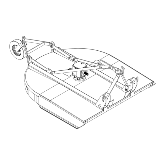
- Page 37 2. A-Frame bar 3. Upper mounting hardware 4. Diagonal brace 5A. Diagonal brace bar mounting hole 5B. Tailwheel pivot hole 6. Tailwheel bracket 9. Tailwheel 10. Height adjustment 13. Driveline (Slip clutch) 14. Clutch shield 15. Rubber shield Figure 31. BB60X, BB72X & BB84X Shipping Configuration DISASSEMBLE SHIPPING UNIT Remove cap screws (13) and flange lock nuts (14) that are securing A-frame bars (2) to the cutting height...
- Page 38 INSTALL A-FRAME INSTALL A-FRAME TO DIAGONAL BRACE BARS BB48X Cutters: Attach A-frame bars (6) to the inside of front mast plates. Secure into position using carriage bolts (23), sleeves (19), flat washers (48), and flange lock nuts (12). BB48X BB48X STANDARD HITCH 6.
- Page 39 INSTALL TAILWHEEL INSTALL DUAL TAILWHEEL BB84XD (OPTIONAL) 1. Attach tailwheel bracket (6) to cutter at the 1. Attach dual tailwheel (1) to main frame (2) using tailwheel pivot holes (5B) using cap screw (13) and position 5B and desired height adjustment holes as flange lock nut (14) previously removed.
- Page 40 BB60X, BB72X & BB84X Standard & Quick 3. To prevent seal damage, carefully push driveline onto gearbox input shaft until it contacts the Hitch Set-Up gearbox housing. 1. Leave A-frame and top link attached together. 4. Place retaining ring (6) in slot on input shaft and 2.
- Page 41 3. Install driveline onto gearbox input shaft and • If this machine is not equipped with full chain, secure with bolt (1) and nut (2). rubber, or steel band shielding, operation must be stopped when anyone comes within 300 feet 4.
- Page 42 INSTALL OPTIONAL CHECK CHAINS 2. Attach lower end of check chain (3) to mast plate (9 or 11) with bolt (6), washer (7), and nut (8). Check chains are used to carry the front of cutter at a 3. Attach keyhole brackets (2) to each side of tractor set height.
- Page 43 PARTS INDEX BRUSHBULL Rotary Cutters: BB48X, BB60X, BB72X, BB84X BRUSHBULL™ STANDARD-DUTY MAIN ASSEMBLY ......44-45 GEARBOX ASSEMBLY (FLAT-TOP) .
- Page 44 BRUSHBULL STANDARD-DUTY MAIN ASSEMBLY BB48X, BB60X, BB72X & BB84X (BB84X SHOWN) 65 - Safety Decal Set 66 - Complete Decal Set 68 - Spanish Safety Decal Set PART DESCRIPTION PART DESCRIPTION 57236 Rear band - BB48X 57239 Diagonal brace BB48X 57210 Rear band - BB60X 1023060...
- Page 45 BB48X, BB60X, BB72X & BB84X MAIN ASSEMBLY PARTS LIST PART DESCRIPTION PART DESCRIPTION 4676 4 x 15 Notat tire & rim 19025 14 5/8 NC Flange lock nut 15349 1/2 NC x 3 Shear bolt GR2 -or- 40775 Spirol pin 10 mm x 65 mm 1024632 1/2 NC x 3 HHCS GR8 (Slip clutch only) 1030524...
- Page 46 GEARBOX ASSEMBLY - (FLAT TOP) REF PART QTY DESCRIPTION 58800 Gearbox repair asy (BB48X) - S/N 1159928 and Below 58801 Gearbox repair asy (BB60X) - S/N 1159928 and Below 58802 Gearbox repair asy (BB72X) - S/N 1159928 and Below 58803 Gearbox repair asy (BB84X) 57458 Gear, crown 25T (BB48X)
- Page 47 GEARBOX ASSEMBLY PARTS LIST (Continued) REF PART DESCRIPTION REF PART DESCRIPTION 20890 Bearing-Ball 57094 Shim kit 44 x 30.3 x 1 (BB84X) 20897 Ring retainer 81mm internal (BB48X, 57473 Flat washer 21 x 37 x 3 BB60X, BB72X) (BB48X & BB60X) Cotter pin 57474 Flat washer 25 x 48 x 2.5 (BB72X)
- Page 48 GEARBOX ASSEMBLY (CAST/CROWN TOP) REF PART DESCRIPTION REF PART DESCRIPTION ----- 4 Lock washer 1032587 1 Gearbox repair assembly (BB48X [ball bearing] S/N 1159929 & above) ----- 4 M10 x 1.5 x 25 cap screw 1032588 1 Gearbox repair assembly (BB60X 1018331 1 1"...
- Page 49 BB48X STANDARD DRIVELINE ASSEMBLY Identified by ribbed shields and grease fittings in cross bearing caps. PART DESCRIPTION 601737 Complete driveline asy 1044051 Complete collar yoke C12 1-3/8 - 6 1044050 Lock collar repair kit 1044052 Cross & bearing kit 605246 Outer yoke &...
- Page 50 BB48X COMER STANDARD DRIVELINE ASSEMBLY PART DESCRIPTION 1009509 Complete 540 driveline asy 1001300 Complete collar yoke C12 1-3/8 - 6 38478 Cross & bearing kit 1019442 Outer cone fix ring 30922 Protection fixing screw 1019444 Inner cone fix ring 30917 Chain shield tether 1001340 Lock collar repair kit...
- Page 51 BB60X STANDARD DRIVELINE ASSEMBLY Identified by ribbed shields and grease fittings in cross bearing caps. PART DESCRIPTION 601738 Complete driveline asy 1044051 Complete collar yoke C12 1-3/8 - 6 1044050 Lock collar repair kit 1044052 Cross & bearing kit 605252 Outer yoke &...
- Page 52 BB60X COMER STANDARD DRIVELINE ASSEMBLY PART DESCRIPTION 1009510 Complete 540 driveline 1001300 Complete collar yoke C12 1-3/8 - 6 38478 Cross & bearing kit 1019442 Outer cone fix ring 30922 Protection fixing screw 1019444 Inner cone fix ring 30917 Chain shielding tether 1001340 Lock collar repair kit 1019445...
- Page 53 BB48X & BB60X SLIP CLUTCH DRIVELINE ASSEMBLY (OPTIONAL) Identified by ribbed shields and grease fittings in cross bearing caps. PART DESCRIPTION 601749 Complete driveline and clutch asy 1044051 Complete collar yoke C12 1-3/8 - 6 1044050 Lock collar repair kit 1044052 Cross &...
- Page 54 BB48X & BB60X COMER SLIP CLUTCH DRIVELINE ASSEMBLY (OPTIONAL) PART DESCRIPTION 1020900 Complete 540 driveline assembly 1001300 Complete collar yoke C12 1-3/8 - 6 38478 Cross & bearing kit 1019442 Outer cone fix ring 30922 Protection fixing ring 1019444 Inner come fix ring 30917 Chain shield tether 1001340...
- Page 55 BB72X SLIP CLUTCH DRIVELINE ASSEMBLY Identified by ribbed shields and grease fittings in cross bearing caps. PART DESCRIPTION 601750 Complete driveline and clutch asy 1044051 Complete collar yoke C12 1-3/8 - 6 1044050 Lock collar repair kit 1044052 Cross & bearing kit 605252 Outer yoke &...
- Page 56 BB72X COMER SLIP CLUTCH DRIVELINE ASSEMBLY PART DESCRIPTION PART DESCRIPTION 1001316 Flanged hub F12 1020901 Complete 540 driveline asy 1001317 Pressure plate 1001300 Complete collar yoke C12 1-3/8 - 6 1001318 Bolt & nut M10 x 80 38478 Cross and bearing kit 1001315 Bolt &...
- Page 57 BB84X SLIP CLUTCH DRIVELINE ASSEMBLY Identified by ribbed shields and grease fittings in cross bearing caps. PART DESCRIPTION 601751 Complete driveline and clutch asy 605274 Complete collar yoke 605275 Lock collar repair kit 605276 Cross & bearing kit 605277 Outer yoke & tube 605278 Inner yoke &...
- Page 58 BB84X COMER SLIP CLUTCH DRIVELINE ASSEMBLY PART PART PART PART DESCRIPTION DESCRIPTION 60 Series 50 Series 60 Series 50 Series 1024144 1024144 Complete driveline asy 1029691 1028782 Flange hub 1001325 1028775 Complete collar yoke 1028783 1028783 Inner plate 30962 36990 Cross and bearing kit 1028784 1028784 Intermediate plate...
- Page 59 BB84X WALTERSCHEID SLIP CLUTCH DRIVELINE ASSEMBLY REF PART DESCRIPTION REF PART DESCRIPTION 40574 Yoke 1-3/8 - 6 spline 57410 Shaft assembly, male (complete with guard) Cross & bearing kit Shaft assembly, female 40764 Spring pin 10 x 80 (complete with guard) 40575 Inboard yoke 57438...
- Page 60 FRONT RUBBER SHIELDING (STANDARD) PART DESCRIPTION 1013207 Rubber shield kit - BB48X 1013208 Rubber shield kit 5 ft - BB60X 1013209 Rubber shield kit 6 ft - BB72X 1023042 Rubber shield kit 7 ft - BB84X 1004128 Rubber deflector 25.25 - BB48X 1004129 Rubber deflector 31.25 - BB60X 1004130...
- Page 61 BOLT TORQUE CHART Always tighten hardware to these values unless a different torque value or tightening procedure is listed for a specific application. Fasteners must always be replaced with the same grade as specified in the manual parts list. Always use the proper tool for tightening hardware: SAE for SAE hardware and Metric for metric hardware. Make sure fastener threads are clean and you start thread engagement properly.
- Page 62 BOLT SIZE CHART NOTE: Chart shows bolt thread sizes and corresponding head (wrench) sizes for standard SAE and metric bolts. SAE Bolt Thread Sizes 5/16 Metric Bolt Thread Sizes 10MM 12MM 14MM 16MM 18MM ABBREVIATIONS AG .............. Agriculture MPa............Mega Pascal ASABE ....American Society of Agricultural &...
-
Page 63: Index To Parts Lists
INDEX ASSEMBLY Quick Hitch Dealer Set-Up Instructions Top Link Adjustment BB60X, BB72X, BB84X DEALER CHECK LISTS Quick Hitch Delivery (Dealer’s Responsibility) Standard Hitch Pre-Delivery (Dealer’s Responsibility) Driveline Attachment DEALER SERVICE Interference Check Crossbar PTO Installation & Removal Installation Shortening Removal Mowing Speed Gearbox Maintenance Operating Technique... - Page 64 The limited warranty covers any defects in the material and/or workmanship. Following the proper, recommended installation by an authorized Woods Dealer and normal use of a Woods mounting and backhoe or loader, if a tractor incurs damage resulting from the attachment, Woods will cover the existing tractor warranty in the event the manufacturer voids its tractor warranty because of the attachment.
- Page 65 Woods logo are trademarks of Woods Equipment Company. All other trademarks, trade names, or service marks not owned by Woods Equipment Company that appear in this manual are the property of their respective companies or mark holders. Specifications subject to change without notice.
- Page 66 Woods logo are trademarks of Woods Equipment Company. All other trademarks, trade names, or service marks not owned by Woods Equipment Company that appear in this manual are the property of their respec- tive companies or mark holders. Specifications subject to change without notice.
Need help?
Do you have a question about the BRUSHBULL BB48X and is the answer not in the manual?
Questions and answers