Table of Contents
Advertisement
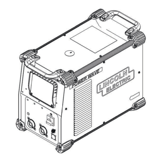
Operator's Manual
POWER WAVE
Register your machine:
www.lincolnelectric.com/register
Authorized Service and Distributor Locator:
www.lincolnelectric.com/locator
Save for future reference
Date Purchased
Code: (ex: 10859)
Serial: (ex: U1060512345)
IM10294
| Issue D ate July-16
© Lincoln Global, Inc. All Rights Reserved.
®
R350
For use with machines having Code Numbers:
12482
Need Help? Call 1.888.935.3877
to talk to a Service Representative
Hours of Operation:
8:00 AM to 6:00 PM (ET) Mon. thru Fri.
After hours?
Use "Ask the Experts" at lincolnelectric.com
A Lincoln Service Representative will contact you
no later than the following business day.
For Service outside the USA:
Email: globalservice@lincolnelectric.com
Advertisement
Table of Contents

Related Manuals for Lincoln Electric POWER WAVE R350


Summary of Contents for Lincoln Electric POWER WAVE R350
- Page 1 Operator’s Manual POWER WAVE ® R350 For use with machines having Code Numbers: 12482 Need Help? Call 1.888.935.3877 Register your machine: to talk to a Service Representative www.lincolnelectric.com/register Authorized Service and Distributor Locator: Hours of Operation: www.lincolnelectric.com/locator 8:00 AM to 6:00 PM (ET) Mon. thru Fri. Save for future reference After hours? Use “Ask the Experts”...
- Page 2 THANK YOU FOR SELECTING A QUALITY PRODUCT BY KEEP YOUR HEAD OUT OF THE FUMES. DON’T get too close to the arc. LINCOLN ELEC TRIC. Use corrective lenses if necessary to stay a reasonable distance away from the arc. READ and obey the Safety Data PLEASE EXAMINE CARTON AND EQUIPMENT FOR Sheet (SDS) and the warning label DAMAGE IMMEDIATELY...
- Page 3 W117.2-1974. A Free copy of “Arc Welding Safety” booklet E205 is available from the Lincoln Electric Company, 2.d. All welders should use the following procedures in order to 22801 St. Clair Avenue, Cleveland, Ohio 44117-1199.
- Page 4 SAFETY ELECTRIC SHOCK ARC RAYS CAN BURN. CAN KILL. 3.a. The electrode and work (or ground) circuits are 4.a. Use a shield with the proper filter and cover plates to protect your electrically “hot” when the welder is on. Do eyes from sparks and the rays of the arc when welding or not touch these “hot”...
- Page 5 SAFETY WELDING AND CUTTING CYLINDER MAY EXPLODE IF SPARKS CAN CAUSE DAMAGED. FIRE OR EXPLOSION. 7.a. Use only compressed gas cylinders containing the correct shielding gas for the process used 6.a. Remove fire hazards from the welding area. If and properly operating regulators designed for this is not possible, cover them to prevent the welding sparks the gas and pressure used.
-
Page 6: Table Of Contents
TABLE OF CONTENTS Page Installation........................Section A Technical Specifications ....................A-1, A-2 Safety Precautions .......................A-3 Location, Lifting ......................A-3 Stacking ........................A-3 Tilting..........................A-3 Input and Ground Connections ..................A-3 Machine Grounding .......................A-3 High Frequency Protection....................A-3 Input Connection ........................A-4 Input Fuse and Supply Wire ..................A-4 Input Voltage Selection ....................A-4 Power Cord Replacement .....................A-4 Connection Diagram .....................A-5 Recommended Work Cable Sizes ................A-6... -
Page 7: Installation
INSTALLATION TECHNICAL SPECIFICATIONS - POWER WAVE R350 ® POWER SOURCE-INPUT VOLTAGE AND CURRENT Model Duty Cycle Power Factor @ Input Voltage ± 10% Input Amperes Idle Power (1 Phase in parenthesis) Rated Output 40% rating 19/17/14 380-415/460/575 K3022-2 50/60 Hz 300 Watts Max. - Page 8 INSTALLATION WELDING PROCESS OUTPUT RANGE (AMPERES) OCV (U PROCESS Mean Peak GMAW 40-70V GMAW-Pulse 40-350A FCAW 5-350A GTAW-DC SMAW 55-325A PHYSICAL DIMENSIONS MODEL HEIGHT WEIGHT WIDTH DEPTH K3022-2 24.80in ( 630mm) 85 lbs (39 kg)* 20.40 in ( 518 mm) 14.00in ( 356 mm) TEMPERATURE RANGES OPERATING TEMPERATURE RANGE...
-
Page 9: Safety Precautions
INSTALLATION LIFTING SAFETY PRECAUTIONS Read this entire installation section before you start installa- Both handles should be used when lifting POWER WAVE® R350. When using a crane or overhead device a lifting strap should be tion. connected to both handles. Do not attempt to lift the POWER WARNING WAVE®... -
Page 10: Input Connection
INSTALLATION INPUT CONNECTION WARNING The POWER WAVE R350 ON/OFF ® WARNING switch is not intended as a service Only a qualified electrician should disconnect for this equipment. Only connect the input leads to the a qualified electrician should con- nect the input leads to the POWER POWER WAVE R350. -
Page 11: Connection Diagram
INSTALLATION CONNECTION DIAGRAM GMAW (MIG) WELDING An arclink compatible wire feeder is recommended for Mig welding. Refer to Figure A.2 for the connection details. FIGURE A.2 POWER WAVE ® R350... -
Page 12: Recommended Work Cable Sizes
“Output Cable Guidelines” below. Excessive volt- Connect the electrode and work cables between the age drops caused by undersized welding cables and appropriate output studs of the POWER WAVE R350 poor connections often result in unsatisfactory weld- per the following guidelines: ing performance. -
Page 13: Cable Inductance And Its Effects On Welding
The loop area is defined by the separation distance between The POWER WAVE R350 has the ability to automati- the electrode and work cables, and the overall welding cally sense when remote sense leads are connected. - Page 14 "Voltage Sensing Considerations for Multiple Arc Systems." Negative Electrode Polarity The POWER WAVE R350 has the ability to automati- cally sense the polarity of the sense leads. With this feature there are no set-up requirements for welding with negative electrode polarity.
-
Page 15: Voltage Sensing Considerations For Multiple Arc Systems
INSTALLATION VOLTAGE SENSING If Sense Leads ARE Used: CONSIDERATIONS FOR MULTIPLE • Position the sense leads out of the path of the ARC SYSTEMS weld current. Especially any current paths com- mon to adjacent arcs. Current from adjacent arcs can induce voltage into each others current paths Special care must be taken when more than one arc that can be misinterpreted by the power sources, is welding simultaneously on a single part. - Page 16 A-10 A-10 INSTALLATION • For circumferential applications, connect all work leads on one side of the weld joint, and all of the work voltage sense leads on the opposite side, such that they are out of the current path. (See Figure 8.A) FIGURE A.8 POWER WAVE ®...
-
Page 17: Control Cable Connections
The wire feeder connection power needs of the Power Wave / Power Feed sys- on the POWER WAVE R350 is located in the upper- tems. Most are designed to be connected end to end right corner of the case back. The K2709 series exter- for ease of extension. -
Page 18: Operation
OPERATION GRAPHIC SYMBOLS THAT APPEAR ON SAFETY PRECAUTIONS THIS MACHINE OR IN THIS MANUAL READ AND UNDERSTAND ENTIRE SECTION BEFORE OPERATING MACHINE. WARNING OR WARNING CAUTION • ELECTRIC SHOCK CAN KILL. • Do not touch electrically live part or electrode with skin or DANGEROUS wet clothing. -
Page 19: Product Description
OPERATION PRODUCT DESCRIPTION RECOMMENDED PROCESSES PRODUCT SUMMARY The POWER WAVE R350 is a high speed, multi- ® The POWER WAVE ® R350 is a portable multi-process process power source capable of regulating the cur- power source with high-end functionality capable of rent, voltage, or power of the welding arc. -
Page 20: Design Features
Service Manual for this machine. (See Troubleshooting Section for operational functions.) NOTE: The Power Wave R350 status light will flash green, and sometimes red and green, for up to one minute when the machine is first turned on. This is a normal situation as the machine goes through a self test at power up. -
Page 21: Case Back Controls
5. ETHERNET CONNECTOR (RJ-45): Used for ArcLink ® XT communication. Also used for diag- (See Figure B.2) nostics and reprogramming the Power Wave R350. Function 1. 115V / 15A DUPLEX RECEPTACLE AND Transmit + CIRCUIT BREAKER 1 (10 AMP): Provides protec- Transmit - tion for the 115V auxiliary. -
Page 22: Common Welding Procedures
POWER WAVE R350 at the factory, refer to the beyond the control of The Lincoln Electric ® Weld Set Reference Guide supplied with the machine Company affect the results obtained in applying or available at www.powerwavesoftware.com. - Page 23 OPERATION GTAW (TIG) WELDING PULSE WELDING The welding current can be set through a PF10M or Pulse welding procedures are set by controlling an PF25M wire feeder. overall “arc length” variable. When pulse welding, the arc voltage is highly dependent upon the waveform. The TIG mode features continuous control from 5 to The peak current, back ground current, rise time, fall 350 amps with the use of an optional foot amptrol...
- Page 24 OPERATION Most pulse welding programs are synergic. As the wire feed speed is adjusted, the POWER WAVE ® R350 will automatically recalculate the waveform parameters to maintain similar arc properties. The POWER WAVE R350 utilizes “adaptive control” ® to compensate for changes in the electrical stick-out while welding.
-
Page 25: Accessories
ACCESSORIES Welding Fume Extractors KITS, OPTIONS AND ACCESSORIES Lincoln offers a wide range of fume extraction environmental All Kits Options and Accessories are found on the Web site: system solutions, ranging from portable systems easily (www.lincolnelectric.com) wheeled around a shop to shop-wide central systems ser- vicing many dedicated welding stations. -
Page 26: Maintenance
MAINTENANCE SAFETY PRECAUTIONS WARNING ELECTRIC SHOCK can kill. • Do not operate with covers removed. • Turn off power source before installing or servicing. • Do not touch electrically hot parts. • Turn the input power to the welding power source off at the fuse box before working in the terminal strip. -
Page 27: Troubleshooting
HOW TO USE TROUBLESHOOTING GUIDE WARNING Service and Repair should only be performed by Lincoln Electric Factory Trained Personnel. Unauthorized repairs performed on this equipment may result in danger to the technician and machine operator and will invalidate your factory warranty. For your safety and to avoid Electrical Shock, please observe all safety notes and precautions detailed throughout this manual. - Page 28 TROUBLESHOOTING USING THE STATUS LED TO Included in this section is information about the Status TROUBLESHOOT SYSTEM PROBLEMS Lights and some basic troubleshooting charts for both machine and weld performance. There are two status lights that display error codes. If a problem occurs it is important to note the condition of the The status lights for the main control board is a dual-color status lights.
- Page 29 TROUBLESHOOTING Observe all Safety Guidelines detailed throughout this manual ERROR CODES FOR THE POWER WAVE R350 ® The following is a partial list of possible error codes for the POWER WAVE R350. For a complete listing consult ® the Service Manual for this machine. MAIN CONTROL BOARD ( “STATUS”...
- Page 30 Motor Overcurrent a short term average to protect drive circuitry. Shutdown #1 The Shutdown inputs on the Power Wave R350 have been dis- abled. The presence of these errors indicates the Feed Head Shutdown #2 Control PCB may contain the wrong operating software.
- Page 31 3. Major physical or electrical dam- 3. Contact your local authorized age is evident when the covers Lincoln Electric Field Service are removed. facility for technical assistance. Machine will not power up (no lights) 1. No Input Power 1.
- Page 32 TROUBLESHOOTING Observe all Safety Guidelines detailed throughout this manual PROBLEMS POSSIBLE RECOMMENDED (SYMPTOMS) CAUSE COURSE OF ACTION Thermal LED is ON Improper fan operation Basic Machine Problems (Continued) Thermal LED is ON 1. Improper fan operation. 1. Check for proper fan operation. Fan should run in a low speed setting when the machine is idle and in a high speed when the...
- Page 33 TROUBLESHOOTING Observe all Safety Guidelines detailed throughout this manual PROBLEMS POSSIBLE RECOMMENDED (SYMPTOMS) CAUSE COURSE OF ACTION Weld and Arc Quality Problems (Continued) Wire burns back to tip at the end of 1. Burnback Time 1. Reduce burnback time and/or the weld.
- Page 34 TROUBLESHOOTING Observe all Safety Guidelines detailed throughout this manual PROBLEMS POSSIBLE RECOMMENDED (SYMPTOMS) CAUSE COURSE OF ACTION Ethernet Cannot Connect 1. Physical connection. 1. Verify that the correct patch cable or cross over cable is being used (refer to local IT department for assistance).
- Page 35 DIAGRAMS xxxxxxx xxxxxxx POWER WAVE R350 ®...
- Page 36 DIMENSION PRINT 27.44 22.25 13.87 18.81 6.00 18.31 POWER WAVE R350 ®...
- Page 37 Power Wave R350 CCC - 12482...
- Page 38 P-884-A INDEX OF SUB ASSEMBLIES P-884-B.2 MISCELLANEOUS ITEMS P-884-C CASE FRONT ASSEMBLY P-884-D BASE & POWER CONVERSION ASSEMBLY P-884-E VERTICAL DIVIDER PANEL ASBLY P-884-F OUTPUT CHOKE ASSEMBLY P-884-G CASE BACK ASSEMBLY P-884-H ROOF ASSEMBLY Power Wave R350 CCC - 12482...
- Page 39 Index of Sub Assemblies - 12482 P-884-A.jpg Power Wave R350 CCC - 12482...
- Page 40 Miscellaneous Items PART NUMBER DESCRIPTION 9SG6094 PRIMARY CONTROL HARNESS 9SM19969-13 ETHERNET PATCH CABLE ASBLY Power Wave R350 CCC - 12482...
- Page 41 Miscellaneous Items No Image Power Wave R350 CCC - 12482...
- Page 42 OUTPUT STUD COVER 9SS9262-184 WASHER 9SS9225-100 SELF TAPPING SCREW 9SS9225-99 SELF TAPPING SCREW 9SS9262-80 PLAIN WASHER 9SE106A-15 LOCKWASHER 9SCF000021 1/2-13X1.00HHCS 9SS18657 SQUARE FLANGE FEMALE RECEPTACLE 9SS8025-118 SELF TAPPING SCREW 9SL15069 COVER PLATE 9SS9225-99 SELF TAPPING SCREW Power Wave R350 CCC - 12482...
- Page 43 Case Front Assembly PART NUMBER DESCRIPTION 9SG6529 UI TRIM 9SS23740-1 LED PANEL MOUNT ASBLY 9ST13657-7H24 LED-T-1 3/4BI-COLORRED/GREEN Power Wave R350 CCC - 12482...
- Page 44 Case Front Assembly P-884-C.jpg Power Wave R350 CCC - 12482...
- Page 45 9ST9187-13 #10-24HLN-1817/1-NYLON INSERT 9SG6037-1 POWER BOARD ASBLY 9ST13359-29 THERMOSTAT 9SM21469-2 POWER BOARD UPPER BRACKET 9SS9225-100 SELF TAPPING SCREW 9SE106A-1 LOCKWASHER 9SS9262-27 PLAIN WASHER 9SM15045-100 ACOUSTICAL FOAM 9ST13260-4 DECAL-EARTH GROUND CONN 9SCF000010 #10-24HN 9SE106A-1 LOCKWASHER Power Wave R350 CCC - 12482...
- Page 46 Base & Power Conversion Assembly P-884-D.jpg Power Wave R350 CCC - 12482...
- Page 47 CONTROL BOARD ASBLY 9ST9187-13 #10-24HLN-1817/1-NYLON INSERT 9ST12380-1 BUSHING 9SS18858-11 SUPPRESSOR ASBLY 9SG8554 NAMEPLATE 9ST9187-13 #10-24HLN-1817/1-NYLON INSERT 9SS9225-99 SELF TAPPING SCREW 9SG6571-2 115V SUPPLY PC BD ASBLY 9SS19300-7 SUPPORTPCBSNAP-IN0.63 9ST9187-13 #10-24HLN-1817/1-NYLON INSERT 9SS18491-3 M.O.V. ASBLY Power Wave R350 CCC - 12482...
- Page 48 Vertical Divider Panel Asbly P-884-E.jpg Power Wave R350 CCC - 12482...
- Page 49 1/4-20HN 9SM22372 BUS BAR 9SCF000015 1/4-20X1.00HHCS 9SS9262-98 PLAIN WASHER 9SE106A-2 LOCKWASHER 9SCF000017 1/4-20HN 9SCF000015 1/4-20X1.00HHCS 9SS9262-98 PLAIN WASHER 9SE106A-2 LOCKWASHER 9SCF000017 1/4-20HN 9SS10404-137 RESISTOR-WW100W2005% 9ST4479-A INSULATING WASHER 9SS9262-27 PLAIN WASHER 9ST9695-1 LOCKWASHER 9SCF000191 #10-24X7.50RHS Power Wave R350 CCC - 12482...
- Page 50 Output Choke Assembly PART NUMBER DESCRIPTION 9SS9225-99 SELF TAPPING SCREW Power Wave R350 CCC - 12482...
- Page 51 Output Choke Assembly P-884-F.jpg Power Wave R350 CCC - 12482...
- Page 52 CONNECTOR ADAPTER PLATE 9SS8025-96 SELF TAPPING SCREW 9ST9187-13 #10-24HLN-1817/1-NYLON INSERT 9SS17062-9 CABLE CONNECTOR CAP 9SL15108 LOUVER COVER PLATE 9SS9225-99 SELF TAPPING SCREW 9SS9225-99 SELF TAPPING SCREW 9SG6602 RECEPTACLE ASSEMBLY 9ST9695-1 LOCKWASHER 9SCF000010 #10-24HN 9SS28056-6 RATING PLATE Power Wave R350 CCC - 12482...
- Page 53 CONNECTOR & LEAD ASBLY 9SS12021-73 BOX RECEPTACLE SOLID SHELL 9SS8025-118 SELF TAPPING SCREW 9SS17062-10 CABLE CONNECTOR CAP 9SS17062-11 CABLE CONNECTOR CAP 9SG6539 WIRE DRIVE HARNESS 9SS12021-72 BOX RECEPTACLE SOLID SHELL 9SS25438-4 ADAPTER PLATE 9SS8025-96 SELF TAPPING SCREW Power Wave R350 CCC - 12482...
- Page 54 Case Back Assembly P-884-G.jpg Power Wave R350 CCC - 12482...
- Page 55 POWERWAVE LOGO 9SS28039-2 DECAL GREEN INITIATIVE 9SS9262-182 PLAIN WASHER 9SS9225-100 SELF TAPPING SCREW 9SS9225-99 SELF TAPPING SCREW 9SM22119 WIRE DRIVE INTERFACE ASSEMBLY 9SM22120 WIRE DRIVE PCB BRACKET 9SS28626-5 FEEDHEAD PC BD ASBLY 9ST9187-13 #10-24HLN-1817/1-NYLON INSERT Power Wave R350 CCC - 12482...
- Page 56 Roof Assembly PART NUMBER DESCRIPTION 9ST13637-6 DIODE-BRIDGE35A400VF-W1-PH 9SS9262-27 PLAIN WASHER 9SE106A-1 LOCKWASHER 9SCF000010 #10-24HN 9SM19540-3 VOLTAGE SENSE SELECT PC BD ASBLY 9SS9225-99 SELF TAPPING SCREW 9SG6536-5 WIRING DIAGRAM Power Wave R350 CCC - 12482...
- Page 57 Roof Assembly P-884-H.jpg Power Wave R350 CCC - 12482...
- Page 58 WARNING Do not touch electrically live parts or Keep flammable materials away. Wear eye, ear and body protection. electrode with skin or wet clothing. Insulate yourself from work and AVISO DE ground. Spanish PRECAuCION No toque las partes o los electrodos Mantenga el material combustible Protéjase los ojos, los oídos y el bajo carga con la piel o ropa moja-...
- Page 59 WARNING Keep your head out of fumes. Turn power off before servicing. Do not operate with panel open or Use ventilation or exhaust to guards off. remove fumes from breathing zone. AVISO DE Spanish PRECAuCION Los humos fuera de la zona de res- Desconectar el cable de ali- No operar con panel abierto o piración.
- Page 60 Lincoln Electric for advice or information about their use of our products. We respond to our customers based on the best information in our possession at that time. Lincoln Electric is not in a position to warrant or guarantee such advice, and assumes no liability, with respect to such information or advice.
Need help?
Do you have a question about the POWER WAVE R350 and is the answer not in the manual?
Questions and answers