Table of Contents
Advertisement
Quick Links
Download this manual
See also:
Service Manual
Operator's Manual
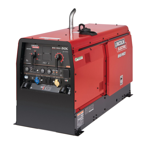
BIG RED
Register your machine:
www.lincolnelectric.com/register
Authorized Service and Distributor Locator:
www.lincolnelectric.com/locator
Save for future reference
Date Purchased
Code: (ex: 10859)
Serial: (ex: U1060512345)
IM10025-B
| Issue D ate Oct-15
© Lincoln Global, Inc. All Rights Reserved.
™
500
For use with machines having Code Numbers:
11585, 11871, 12449
Need Help? Call 1.888.935.3877
to talk to a Service Representative
Hours of Operation:
8:00 AM to 6:00 PM (ET) Mon. thru Fri.
After hours?
Use "Ask the Experts" at lincolnelectric.com
A Lincoln Service Representative will contact you
no later than the following business day.
For Service outside the USA:
Email: globalservice@lincolnelectric.com
Advertisement
Table of Contents

Related Manuals for Lincoln Electric BIG RED 500


Summary of Contents for Lincoln Electric BIG RED 500
- Page 1 Operator’s Manual ™ BIG RED For use with machines having Code Numbers: 11585, 11871, 12449 Need Help? Call 1.888.935.3877 Register your machine: to talk to a Service Representative www.lincolnelectric.com/register Authorized Service and Distributor Locator: Hours of Operation: www.lincolnelectric.com/locator 8:00 AM to 6:00 PM (ET) Mon. thru Fri. Save for future reference After hours? Use “Ask the Experts”...
- Page 2 THANK YOU FOR SELECTING A QUALITY PRODUCT BY KEEP YOUR HEAD OUT OF THE FUMES. DON’T get too close to the arc. LINCOLN ELEC TRIC. Use corrective lenses if necessary to stay a reasonable distance away from the arc. READ and obey the Safety Data PLEASE EXAMINE CARTON AND EQUIPMENT FOR Sheet (SDS) and the warning label DAMAGE IMMEDIATELY...
- Page 3 W117.2-1974. A Free copy of “Arc Welding Safety” booklet E205 is available from the Lincoln Electric Company, 2.d. All welders should use the following procedures in order to 22801 St. Clair Avenue, Cleveland, Ohio 44117-1199.
-
Page 4: Electric Shock Can Kill
SAFETY ELECTRIC SHOCK ARC RAYS CAN BURN. CAN KILL. 3.a. The electrode and work (or ground) circuits are 4.a. Use a shield with the proper filter and cover plates to protect your electrically “hot” when the welder is on. Do eyes from sparks and the rays of the arc when welding or not touch these “hot”... - Page 5 SAFETY WELDING AND CUTTING CYLINDER MAY EXPLODE IF SPARKS CAN CAUSE DAMAGED. FIRE OR EXPLOSION. 7.a. Use only compressed gas cylinders containing the correct shielding gas for the process used 6.a. Remove fire hazards from the welding area. If and properly operating regulators designed for this is not possible, cover them to prevent the welding sparks the gas and pressure used.
-
Page 6: Table Of Contents
Battery Connection......................A-4 Muffler Outlet Pipe ......................A-5 Spark Arrester .......................A-5 Welding Output Cables, Machine Grounding ...............A-5 Auxiliary Power Receptacles, Residual Device Ready, Standby Power Connections ..A-6 Connection of Lincoln Electric Wire Feeders ...............A-7 ________________________________________________________________________________ Operation.........................Section B Safety Instructions........................B-1 General Description......................B-1 Recommended Applications....................B-1 Controls and Settings ........................B-2... - Page 7 TABLE OF CONTENTS Page Maintenance ....................Section D Safety Precautions ....................D-1 Routine and Periodic Engine Maintenance ............D-1 Oil Filter Change .....................D-2 Air Filter Change .....................D-2 Fuel and Bleeding the Fuel System ..............D-2 Fuel Filters ......................D-3 Battery Handling ................D-3 thru D-4 Servicing Optional Spark Arrestor .................D-4 Replace Service Items ..................D-4 Welder / Generator Maintenance ................D-5 Storage ......................D-5...
-
Page 8: Installation
INSTALLATION TECHNICAL SPECIFICATIONS - BIG RED™ 500 (K2810-1) INPUT - DIESEL ENGINE Make/Model Description Speed (RPM) Displacement Starting Capacities System Deutz 3 cylinder Idle 1890 125 cu. in 12VDC battery Fuel D2011L03i 32HP (24 kw) (2.05L) & Starter (20 US gal) Diesel Engine @ 1800 RPM Full Load 1800... -
Page 9: Safety Precautions
INSTALLATION SAFETY PRECAUTION ANGLE OF OPERATION Read this entire installation section before you start To achieve optimum engine performance the BIG installation. RED™ 500 should be run in a level position. The maximum angle of operation for the Deutz engine is WARNING 20 degrees in direction of control panel angled up and 30 degrees for left, right and control panel angled... -
Page 10: Towing
INSTALLATION TOWING PRE-OPERATION ENGINE SERVICE READ the engine operating and maintenance instruc- Use a recommended trailer for use with this equip- tions supplied with this machine. ment for road, in-plant and yard towing by a vehi- cle(1). If the user adapts a non-Lincoln trailer, he must WARNING assume responsibility that the method of attachment and usage does not result in a safety hazard or dam-... -
Page 11: Engine Break-In
INSTALLATION ENGINE BREAK-IN BATTERY CONNECTION WARNING Lincoln Electric selects high quality, heavy-duty indus- trial engines for the portable welding machines we GASES FROM BATTERY can explode. offer. While it is normal to see a small amount of • Keep sparks, flame and cigarettes crankcase oil consumption during initial operation, away from battery. -
Page 12: Muffler Outlet Pipe
INSTALLATION MUFFLER OUTLET PIPE MACHINE GROUNDING Remove the plastic plug covering the muffler outlet Because this portable engine driven welder creates its tube. Using the clamp provided secure the outlet pipe own power, it is not necessary to connect its frame to to the outlet tube with the pipe positioned such that it an earth ground, unless the machine is connected to will direct the exhaust in the desired position... - Page 13 INSTALLATION RESIDUAL CURRENT DEVICE READY AUXILIARY POWER RECEPTACLES The BIG RED™ 500 is configured to allow for the The auxiliary power of the BIG RED™ 500 consists of addition of a Residual Current Device (RCD) to pro- Single Phase 60Hz Power. Output Voltage is within tect the 240V Single Phase Receptacle.
-
Page 14: Connection Of Lincoln Electric Wire Feeders
------------------------------------------------------------------------ ------------------------------------------------------------------------ The LN-15™ Across-the-Arc model, LN-25™ with or Lincoln Electric does NOT recommend constant without an internal contactor, and LN-25™ PRO may current semiautomatic welding for applications be used with the BIG RED™ 500. -
Page 15: Operation
OPERATION SAFETY INSTRUCTIONS GENERAL DESCRIPTION Read and understand this entire section before The BIG RED™ 500 is a diesel engine driven welder, operating your BIG RED™ 500. offering reliable DC arc welding performance, with outstanding arc characteristics for all welding applica- tions. -
Page 16: Controls And Settings
OPERATION CONTROLS AND SETTINGS All welder and engine controls are located on the case front panel. Refer to Figure B.1 and the explanations that follow. Figure B.1 Case Front Panel Controls 2. OUTPUT CONTROL WELDING CONTROLS (Items 1-5) Provides fine adjustment of the current and open 1. -
Page 17: Engine Controls
OPERATION 5. LOCAL / REMOTE CONTROL SWITCH and 11. OIL PRESSURE GAUGE REMOTE RECEPTACLE An indicator of engine oil pressure. The toggle switch provides the option of controlling 12. ENGINE PROTECTION the welding output at the control panel or remotely. A warning indicator light for high oil temperature or For control at the control panel set the switch in the low oil pressure. -
Page 18: Engine Operation
OPERATION 17. 120 VAC DUPLEX RECEPTACLE 8. Allow the engine to warm up for several minutes before applying a load. Allow a longer warm up Single-pole 20A rated. Provides overload protec- time in cold weather. tion for the 120VAC (5-20R) NEMA Duplex Receptacle. -
Page 19: Arc Gouging
OPERATION WELDER OPERATION For example: to obtain 175 amps and a forceful arc, set the “Output Range Selector” to the 150-330 position and the “Output Current Adjustment” set- DUTY CYCLE ting to get 175 amps. Duty Cycle is the percentage of time the load is being applied in a 10 minute period. -
Page 20: Tig Welding
OPERATION The BIG RED™ 500 can be used for Scratch-Start of DC TIG welding applications. Use the “Output Range Selector” and “Output Control Adjustments” to set the desired current. To initiate a weld, the tungsten electrode is then scratched on the work which establishes the arc. To stop the arc, simply lift the TIG torch away from the work piece. - Page 21 A LINCOLN ELECTRIC WIRE FEEDER difficult to achieve required weld metal properties, or to achieve the required quality of welds needed to Lincoln Electric does NOT recommend constant pass nondestructive tests, when such welds are made current semiautomatic welding for applications under constant current operation.
-
Page 22: Auxiliary Power
OPERATION AUXILIARY POWER: The auxiliary power is independent of the welding power and thus not effected by the weld control set- tings. Simultaneous Welding and Auxiliary Power Loads The auxiliary power ratings are with no welding load. Simultaneous welding and power loads are speci- fied in the following Table B.4. -
Page 23: Accessories
ACCESSORIES OPTIONAL FEATURES K2641-2 FOUR WHEELED STEERABLE YARD TRAILER For in plant and yard towing. Comes standard with a Duo-Hitch™, a 2” Ball and Lunette Eye combination Hitch. K2636-1 TRAILER - Two-wheeled trailer with optional fender and light package. For highway use, consult applicable federal, state, and local laws regarding possible additional requirements. -
Page 24: Maintenance
MAINTENANCE SAFETY PRECAUTIONS WEEKLY Blow out the machine with low pressure air periodical- WARNING ly. In particularly dirty locations, this may be required once a week. Have qualified personnel do the maintenance work. Turn the engine off before working inside ENGINE MAINTENANCE the machine. -
Page 25: Oil Filter Change
MAINTENANCE Use motor oil designed for diesel engines that meets 3. Remove loose dirt from element with compressed air requirements for API service classification or water hose directed from inside out. CC/CD/CE/CF/CF-4/CG-4 or CH-4. Compressed Air: 100 psi maximum with nozzles at least one inch away from element. -
Page 26: Fuel Filters
MAINTENANCE FUEL FILTERS BATTERY HANDLING GASES FROM BATTERY can explode. WARNING • Keep sparks, flame and cigarettes away from battery. To prevent EXPLOSION when: When working on the fuel system • INSTALLING A NEW BATTERY - discon- nect negative cable from old battery first •... -
Page 27: Servicing Optional Spark Arrestor
MAINTENANCE SERVICING OPTIONAL SPARK PREVENTING BATTERY BUCKLING Tighten nuts on battery clamp until snug. ARRESTOR Clean every 100 hours. CHARGING THE BATTERY WARNING When you charge, jump, replace, or otherwise connect bat- tery cables to the battery, be sure the polarity is correct. •... -
Page 28: Welder / Generator Maintenance
MAINTENANCE WELDER / GENERATOR MAINTENANCE STORAGE Store the BIG RED™ 500 in clean, dry protected areas. CLEANING Blow out the generator and controls periodically with low pressure air. Do this at least once a week in particularly dirty areas. BRUSH REMOVAL AND REPLACEMENT It is normal for the brushes and slip rings to wear and dark- en slightly. -
Page 29: Troubleshooting
HOW TO USE TROUBLESHOOTING GUIDE WARNING Service and Repair should only be performed by Lincoln Electric Factory Trained Personnel. Unauthorized repairs performed on this equipment may result in danger to the technician and machine operator and will invalidate your factory warranty. For your safety and to avoid Electrical Shock, please observe all safety notes and precautions detailed throughout this manual. - Page 30 TROUBLESHOOTING Observe all Safety Guidelines detailed throughout this manual PROBLEMS POSSIBLE RECOMMENDED (SYMPTOMS) CAUSE COURSE OF ACTION Major Physical or Electrical Damage 1. Contact your Local Lincoln is Evident. Authorized Field Service Facility. Engine will not crank 1. Battery low. 2.
- Page 31 TROUBLESHOOTING Observe all Safety Guidelines detailed throughout this manual PROBLEMS POSSIBLE RECOMMENDED (SYMPTOMS) CAUSE COURSE OF ACTION Engine shuts down while under a 1. High oil temperature. load. Engine runs rough. 1. Dirty fuel or air filters may need cleaned/replaced. 2.
-
Page 32: Diagrams
DIAGRAMS BIG RED™ 500... - Page 33 DIAGRAMS BIG RED™ 500...
- Page 34 DIAGRAMS BIG RED™ 500...
- Page 35 DIAGRAMS BIG RED™ 500...
- Page 36 DIAGRAMS BIG RED™ 500...
- Page 37 THIS PAGE INTENTIONALLY LEFT BLANK...
- Page 38 Lower Control Panel Assembly P-870-E Reactor Rectifier & Fuel Tank Assembly P-870-F Inner Control Panel Assembly P-870-G Base Battery & Lift Bale Asbly P-870-H Engine & Filter Assembly P-870-J Generator Assembly P-870-K Case Back Assembly P-870-L Covers Assembly Big Red 500 - 12449...
- Page 39 Index of Sub Assemblies - 12449 P-870-A.jpg Big Red 500 - 12449...
- Page 40 THREAD FORMING SCREW (ROLLING) 9SG8477 Decal Carrier 9SCF000010 #10-24HN 9SS9262-27 PLAIN WASHER 9SE106A-1 LOCKWASHER 9ST11525-5 SPEED NUT1/4-20 9SS9225-65 THREAD FORMING SCREW (ROLLING) 9SM22132 CONTROL HANDLE 9ST9967-53 ROLL PIN 9SM22132-2 M6X16 DIN 916 45H THERMAL BLACK OXIDE Big Red 500 - 12449...
- Page 41 Case Front & Control Panel Assembly P-870-C.jpg Big Red 500 - 12449...
- Page 42 COVER CIRCUIT BREAKER 2 POLE 9ST10082-30 SEMS SCREW 9ST4291-A LOCKWASHER 9ST12287-22 CIRCUIT BREAKER-15A 9SS22061-1 CIRCUIT BREAKER BOOT 9ST12287-38 CIRCUIT BREAKER 9SS22061-1 CIRCUIT BREAKER BOOT 9ST14166-9 OUTPUT TERMINAL KIT 9SM13900 OUTPUT TERMINAL ASBLY 9ST3960 FLANGE NUT 9SS8025-91 SELF TAPPING SCREW Big Red 500 - 12449...
- Page 43 INSULATOR 9ST11267-B INSULATOR 9SCF000356 1/4-20X1.50HHB-FULL-GR2-E1817/1 9SS9262-98 PLAIN WASHER 9SE106A-2 LOCKWASHER 9SCF000017 1/4-20HN 9ST9187-13 #10-24HLN-1817/1-NYLON INSERT 9SS9262-98 PLAIN WASHER 9SE106A-2 LOCKWASHER 9SCF000017 1/4-20HN 9ST9187-1 1/4-20HJLN 9SCF000017 1/4-20HN 9SS24982-1 BYPASS FILTER ASBLY 9SS9262-3 PLAIN WASHER 9SE106A-12 LOCKWASHER Big Red 500 - 12449...
- Page 44 Lower Control Panel Assembly PART NUMBER DESCRIPTION 9SCF000010 #10-24HN 9SS9262-27 PLAIN WASHER 9SE106A-1 LOCKWASHER 9SCF000010 #10-24HN 9SS24097-5 SHUNT & LEAD ASBLY 9SS9262-1 PLAIN WASHER 9SE106A-15 LOCKWASHER 9SCF000021 1/2-13X1.00HHCS 9SCF000062 5/16-18X1.00HHCS 9SS9262-121 PLAIN WASHER 9SE106A-14 LOCKWASHER 9SCF000029 5/16-18HN Big Red 500 - 12449...
- Page 45 Lower Control Panel Assembly P-870-D.jpg Big Red 500 - 12449...
- Page 46 FUEL TANK ASSEMBLY 9SG6058 Fuel Tank 9SS20541 FUEL CAP 9SL12505 FUEL SENDER 9SS19564-1 FUEL FITTING (PUSH-IN) 9SS19563 RUBBER PLUG 9SS19564-5 FUEL FITTINGPUSH-IN 9ST10642-301 FLEX TUBE 9ST13777-6 HOSE CLAMP 9SS25771 REDUCUNG BARB TAIL 9ST13777-1 HOSE CLAMP Big Red 500 - 12449...
- Page 47 DESCRIPTION 9SM22238 SELECTOR SWITCH ASBLY 9SM22093 SELECTOR SWITCH - 3 PHASE 9SS9225-68 THREAD FORMING SCREW (CUTTING) 9SCF000413 1/4-20 X 1.00 HHCS 9SS9262-98 PLAIN WASHER 9SE106A-2 LOCKWASHER 9SCF000017 1/4-20HN 9SCF000412 1/4-20 X .50 HHCS 9ST9187-6 LOCKNUT Big Red 500 - 12449...
- Page 48 Reactor, Rectifier & Fuel Tank Assembly P-870-E.jpg Big Red 500 - 12449...
- Page 49 SET SCREW 9SS9262-98 PLAIN WASHER 9SE106A-2 LOCKWASHER 9SCF000198 1/4-28HN 9SS22747 CAPACITOR BRKT ASBLY 9ST9187-16 1/4-20 HLN 9ST12380-4 BUSHING 9SCF000010 #10-24HN 9SS9262-27 PLAIN WASHER 9SE106A-1 LOCKWASHER 9SG6681 HARNESS 9SS14531-5 RELAY SOCKET 9SS9225-61 THREAD FORMING SCREW (ROLLING) Big Red 500 - 12449...
- Page 50 Inner Control Panel Assembly PART NUMBER DESCRIPTION 9SS14293-20 RELAY HEAVY DUTY 12VDC SPDT Big Red 500 - 12449...
- Page 51 Inner Control Panel Assembly P-870-F.jpg Big Red 500 - 12449...
- Page 52 HEX HD CAP SCREW 9SL15175 Left Baffle Assembly 9SL15132-1 LEFT BAFFLE 9SM22141 HOT START TRANSFORMER 9SS9225-68 THREAD FORMING SCREW (CUTTING) 9ST12380-1 BUSHING 9ST13637-5 DIODE-BRIDGE35A800VF-W1-PH 9SS10773-7 INSULATING WASHER 9ST9187-13 #10-24HLN-1817/1-NYLON INSERT 9SM15045-105 ACOUSTICAL FOAM 9ST11525-7 SPEED NUT Big Red 500 - 12449...
- Page 53 LOCKNUT 9SS9225-64 SELF TAPPING SCREW 9SS8070-49 BATTERY CABLE (NEGATIVE) 9SS8070-52 BATTERY CABLE (POSITIVE) 9SS20191-1 BATTERY TERMINAL COVER 9SS17851 DECAL-CAUTION 9SM16197 DECAL-WARNING 9SM22221-1 Rating Plate 9ST13086-169 DECAL-C TICK 9SS17187-11 Battery Cable 9SS14922-2 Battery Cable & Ground Big Red 500 - 12449...
- Page 54 Base, Battery & Lift Bale Asbly P-870-G.jpg Big Red 500 - 12449...
- Page 55 HOSE CLAMP 9ST10642-187 FLEX TUBE 9SS24068 FUEL SHUT-OFF 9SS17400-2 LOCKWASHER-METRIC M12 9SG6593 FLAT PLATE 9SG6637 OIL COOLER BAFFLE 9ST14731-14 METRIC HEX HD SCREW-M8 X1.25 9SS9262-121 PLAIN WASHER 9SE106A-3 LOCKWASHER 9ST14731-38 METRIC HEX HD SCREW-M6 X1.0 Big Red 500 - 12449...
- Page 56 1/4-20X.50HHCS 9ST9187-6 LOCKNUT 9ST14731-38 METRIC HEX HD SCREW-M6 X1.0 9SS9262-98 PLAIN WASHER 9SS17400-3 METRIC LOCKWASHER 9SM16980 OUTLET PIPE ELBOW 9SS28113 CLAMP 2" EXHAUST PIPE 9SS9262-56 PLAIN WASHER 9ST9187-4 LOCKNUT 9ST9054 WASHER 9SCF000123 1/2-13X2.75HHCS 9ST13086-62 DECAL-WARNING Big Red 500 - 12449...
- Page 57 Engine & Filter Assembly P-870-H.jpg Big Red 500 - 12449...
- Page 58 EXCITER STATOR TIE BAR ASBLY 9ST8833-82 HEX HEAD CAP SCREW 9SS9262-56 PLAIN WASHER 9SE106A-16 LOCKWASHER 9ST13483-49 O-RING 9SM9300-85 BEARING 9SL11614-3 STATOR COWLING 9SS9225-64 SELF TAPPING SCREW 9SL11614-3 STATOR COWLING 9SS22415-10 TRIM SEAL 9SS9225-64 SELF TAPPING SCREW 9ST14731-70 METRIC SCREW Big Red 500 - 12449...
- Page 59 SELF TAPPING SCREW 9SL15154 STATOR QUARTER BAFFLE 9SL15154-1 STATOR QUARTER BAFFLE 9SS9225-64 SELF TAPPING SCREW 9ST8833-62 HEX HD CAP SCREW 9SCF000112 3/8-16X1.75HHCS 9SE106A-4 LOCKWASHER 9SM21315-3 BRUSH HOLDER & BRACKET ASBLY 9SS9225-8 THREAD FORMING SCREW (ROLLING) Big Red 500 - 12449...
- Page 60 Generator Assembly P-870-J.jpg Big Red 500 - 12449...
- Page 61 LOCKWASHER 9SCF000344 HEX HD SCREW 9SM22154-1 AIR BOX 9ST9187-16 1/4-20 HLN 9SS9225-64 SELF TAPPING SCREW 9SS9225-64 SELF TAPPING SCREW 9ST9187-16 1/4-20 HLN 9ST14882 DOOR BUMPER 9SS28160 ENGINE SERVICE DECAL 9SL15190 AIR HOSE 9SS10888-33 HOSE CLAMP Big Red 500 - 12449...
- Page 62 Case Back Assembly P-870-K.jpg Big Red 500 - 12449...
- Page 63 9SM22220 FAMILY NAME DECAL 9SL12515-2 DOOR LATCH 9SS9225-64 SELF TAPPING SCREW 9SL16909 Door Slide 9SS9225-64 SELF TAPPING SCREW 9SS25719-3 EDGE GUARD 9SL12084 FUEL TROUGH 9SS12934-1 COVER SEAL 9SG8477 Decal Carrier 9SM21436 CARBON MONOXIDE WARNING DECAL Big Red 500 - 12449...
-
Page 64: Wiring Diagram
Covers Assembly PART NUMBER DESCRIPTION 9SS25896 DECAL-WARNING 9ST13086-205 FUEL WARNING DECAL 9ST14882-1 DOOR BUMPER 9SM22257 CONNECTION LABEL 9SG8472 Wiring Diagram 9SS28039-1 DECAL GREEN INITIATIVE Big Red 500 - 12449... - Page 65 Covers Assembly P-870-L.jpg Big Red 500 - 12449...
- Page 66 Do not touch electrically live parts or Keep flammable materials away. Wear eye, ear and body protection. WARNING electrode with skin or wet clothing. Insulate yourself from work and ground. Spanish No toque las partes o los electrodos Mantenga el material combustible Protéjase los ojos, los oídos y el AVISO DE bajo carga con la piel o ropa mojada.
- Page 67 Keep your head out of fumes. Turn power off before servicing. Do not operate with panel open or WARNING Use ventilation or exhaust to remove guards off. fumes from breathing zone. Spanish Los humos fuera de la zona de res- Desconectar el cable de alimentación No operar con panel abierto o AVISO DE...
- Page 68 Lincoln Electric for advice or information about their use of our products. We respond to our customers based on the best information in our possession at that time. Lincoln Electric is not in a position to warrant or guarantee such advice, and assumes no liability, with respect to such information or advice.
Need help?
Do you have a question about the BIG RED 500 and is the answer not in the manual?
Questions and answers