Advertisement
Quick Links
Advertisement

Related Manuals for Bolton Tools ZX45A


Summary of Contents for Bolton Tools ZX45A
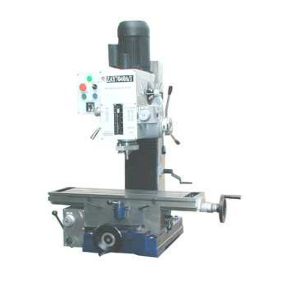
- Page 1 ZX45A POWER FEED BENCH MILLING&DRILLING MACHINE OPERATING MANUAL...
-
Page 2: Table Of Contents
CONTENTS CONTENTS CONTENTS CONTENTS SAFETY WARNING---------------------------3 SPECIFICATION----------------------------4 FEATURES---------------------------------5 INSTALLATION-----------------------------6 OPERATION--------------------------------6 ELECTRICAL SYSTEM------------------------9 TROUBLE SHOOTING-------------------------10 MAINTENANCE------------------------------11... -
Page 3: Safety Warning
SAFETY WARNING 1. READ ALL INSTRUCTIONS BEFORE USING THIS MACHINE 2. KEEP GUARDS IN PLACE AND IN WORKING ORDER 3. KEEP WORK AREA CLEAN, CLUTTERED AREA INVITE INJURIES 4. KEEP CHILDREN AND VISITORS AWAY FROM WORK AREA 5. DRESS PROPERLY, NO LOOSE CLOTHING, GLOVES NECKTIES,OR OTHER JEWELRY TO GET CAUGHT IN MOVING PARTS,WEAR PROTECTIVE HAIR COVERING TO CONTAIN LONG HAIR. -
Page 4: Specification
SPECIFICATION Model ZX45A Max.drilling capacity 1 7/9″ Max.face mill capacity 3 1/7″ Max.end mill capacity 1 1/9″ Max.tapping capacity Max.spindle stroke 5 1/8″ Swivel angle headstock ±90° perpendicular direction Max.distance between spindle nose to 15 5/9″ table Distance between axes of spindle to 10 1/4″... -
Page 5: Features
FEATURES (1) This machine may be used for surface cutting, drilling, milling, boring and tapping. (2) This machine is of fine quality, can be operated easily, it is not limited to skilled operator. (3) The drilling and milling operation can be performed by two methods: 1)Hand operation, which makes quick feeding drilling or slow feeding milling 2)Auto-feed operation, the machine have six different feeding for... -
Page 6: Operation
points OPERATION Notice: Check all parts and safety precautions for proper condition before operation Change speed handle 2.Feed handle 3.micro feed knob 4.Crank 5.Longitudinal handwheel 6.Cross auto-feed handle 7.Cross lock handle 8.Longitudinal lock handle 9.Longitudinal auto- feed handle 10.Cross handwheel 11.Change table feeding knob 12. - Page 7 (6)Adjust the positive depth stop gauge(17) according to working depth. (7)When move the table by hand, adjust longitudinal/cross auto-feed handle(6,9) to middle position, then turn the longitudinal/cross handweel(5,10) to move the table. When move the table by power,open the switch for table feed, turn the knob(11) to select the amount of feed at first,then, press down the handle(9) to turn left for longitudinal moving the table left, press down the handle(9) to turn right for longitudinal moving the table right.
- Page 8 rotate it slightly counter-clockwise to loosen the gib trip. (4)Adjust the gib trip bolt until very slight drag is felt when moving the table. 6. Changing machine speed (1)Turn the power off. (2)To select the proper speed, move the handle(1) to the desired position . (3)If the gear are not engaged, remove the arbor bolt cover.
-
Page 9: Electrical System
End mills Cutter arbor Taps Collets Adapters and sleeves 10.Specification of the T-slot Please refer to figure, purchase or make T-bolts and other table top fixtures to these dimensions. ELECTRICAL SYSTEM WARNING: 1.A fuse must be connected between machine and power. 2.The ground terminal of machine must be grounded properly 3.Don’t open electrical box during operation,if... -
Page 10: Trouble Shooting
SINGLE PHASE CIRCUIT TROUBLE SHOOTING 1. The machine doesn’t run when the power switch is turned ON (a)The knob is in the STOP position (b)A fuse has burned out---Check in the switch box, and replace it necessary. (c)If there is a surge in the current, the circuit breaker may have opened---Press the circuit breaker back, if it is in the open position. - Page 11 (b)The spindle bearing is worn, or is fixed too tight---Turn off the power, unplug the electrical connection, and rotate the spindle by hand.Be sure it freely. If not, adjustment the bearing .If you feel no use in the bearing, you will have to replace it. (c)The spindle has been turning at high speed for a long time---After Long use, turn the machine off for a while to give it a rest, and allow it to cool off.
-
Page 12: Maintenance
(d)The machine may not be stable in the floor--- be sure the machine is firmly mounted to the floor. MAINTENANCE 1. After each use (a) Turn off the power switch. (b) Remove any tool bits, clean and lubricate them, and return them to their storage case. - Page 14 TABLE ASSEMBLY PART NO. DESCRIPTION QTY. JB/T7940.4-1995 Oiler 6 GB/T70-86 Screw M8×16 GB/T117-85 Taper pin 6×25 ZAY7040A-01-021 Leadscrew seat B GB/T8941-85 Retainer ring (external) A34 ZAY7040A-01-005 Bevel gear A ZAY7040A-01-006 Clutch A ZAY7040A-01-037 T-key GB/T70-86 Screw M8×20 GB/T118-85 Taper pin 6×20 ZAY7040A-01-033 Leadscrew seat B ZAY7040A-01-041...
- Page 15 ZAY7040A-01-026 Handle seat B JB/T7270.11-94 Handle HY8310.28, 8×100 GB/T819-85 Screw M5×10 GB/T119-86 Pin 6×10 A GB/T2089-80 Spring 14.5×12 ZAY7040A-01-028 Cover ZAY7040A-01-027 Shaft gear B GB/T70-85 Screw M6×15 ZAY7040A-01-029 Seat Gib (short) ZX32-01-019 GB/T894.1-94 Retainer ring (external) 16 A GB/T894.1-94 Retainer ring (external) 20 A GB/T276-94 Bearing 61804 ZAY7040A-01-019...
- Page 16 ZAY7040A-01-040 Seat ZAY7040A-01T02-001 Square column (A) GB/T93-87 Spring washer 16 GB/T5780-86 Bolt M16×60 GB/T5781-86 Screw M8×12 ZX32-01-010 Guide guard GB/T810-88 Thin nut M16×1.5 GB/T858-77 Stopping washer 16 GB/T70-85 Screw M8×20 GB/T119-86 Pin 8×20 ZX32W-01-006 Support seat GB/T301-94 Bearing 51103 ZX32W-01-007 Bevel gear GB/T276-94 Bearing 6204-2RS...
- Page 18 PART NO. Name Inner hexagonal screw M6×15 GB/T70-85 GB/T93-87 Spring washer 10 ZXT45G-02-004 Washer Gear(Z=34,m=2) ZXT45G-02-031 GB/T9877.1-88 Oil seal 20×35×10 GB65-85 Screw M6×15 ZXT45G-02-033 Bush JB/T 7757.2-95 O shape seal 39.5×3.1 ZXT45G-02-032 Shaft GB/T1096 Key 5×8 GB/T1096 Key 5×25 GB893-76 Inner ring 35 GB/T276-94 Bearing 16003/P6...
- Page 19 ZX32G-02-014(1) Gear ZX32G-02-003 Shaft GB/T1096 Key 5×50 GB/T1096 Key 6×75 ZX32G-02-006(1) Gear ZX32G-02-005(1) Gear ZX32G-02-004(1) Gear GB/T894.1-86 Snap ring 18 GB/T276-94 Bearing 6003-Z/P6 ZX32G-02-018(1) Gear ZX32G-02-019(1) Gear ZX32G-02-020(1) Gear GB/T73-85 Tapered head fasten screw M5×8 ZX32G-02-017 Shaft GB/T1096 Key 5×60 ZX32G-02-024 Gear ZX32G-02-023...
- Page 20 GB/T9877.1-88 Oil seal B35×62×12 ZXT45G-02-011 Connective base GB/T818-85 Screw M5×10 GB/T5782-86 Bolt M16×70 ZXT45G-02-010 Angle meter GB/T5782-86 Bolt M16×60 GB/T70-85 Inner hexagonal screw M12×25 ZXT45G-02-012 Connective plate GB/T93-87 Spring washer 16 GB/T6182-86 Lock nut M16 ZXT45G-02-001 Head body ZXT45G-02-029 Shaft B ZXT45G-02-027 Shaft A JB/T 7941.2-1995...
- Page 21 GB/T1096 Key 5×10 GB/T1096 Key 5×8 ZXT45G-02-028 Shift Lever A ZXT45G-02-018 Long pin shaft ZXT45G-02-025 Lever B GB71-85 Tapered head fasten screw M6×8 ZXT45G-02-023 Pole ZXT45G-02-057 Dexter cover plate ZX32G-02-040 Spring base GB/T70-85 Screw M5×10 GB/T68-85 Screw M5×8 ZX32G-02-047 Spring ZX32G-02-043 Spring cover ZX32G-02-042...
- Page 22 ZXT45G-02-046 Shaft GB/T1096 Key 6×63 GB/T1096-79 Key 5×12 GB/T1096 Key 8×15 Gear (Z=30,m=1.5) ZXT45G-02-045 Gear(Z=43,m=1.5) ZXT45G-02-044 ZXT45G-02-043 Gear(Z=38,m=1.5) GB71-85 Tapered head fasten screw M6×8 Subulate gear Z=15,m=2 ZXT45G-02-042 GB96-85 Washer 5 GB/T70-85 Inner hexagonal screw M5×12 ZXT45G-02-061 ZXT45G-02-059 Lever D ZXT45G-02-058 Lever C ZXT45G-02-009...
- Page 24 PART NO. DESCRIPTION ZX32G-03-001 Spindle GB/T858-88 Stop washer 30 GB/T810-86 Nut M30 × GB/T5780-86 Bolt M6 × ZXT45G-03-001 Graduate rod base ZX32G-03-002 Anti-dust cover GB/T297-94 Bearing 30207/P6 ZX32-03-002 Rack sleeve ZX32G-03-004 Rubber flange GB/T297-94 Bearing 30206/P6 Spring pin φ3 GB/T879-86 ×...
- Page 26 FEED BOX ASSEMBLY PART NO. DESCRIPTION ZXT45G-04-001 Gear shaft GB/T1096-79 Key 8×52 ZXT45G-04-002 Bearing spacer GB/T308-84 Steel ball 7 ZXT45G-04-003 Worm ZXT45G-04-005 Clutch GB65-85 Round head screw M5×15 ZXT45G-04-006 Spacer ZXT45G-04-007 Spacer GB/T1096-79 Key 8×15 ZXT45G-04-011 Spring GB/T308-84 Steel ball 7 ZXT45G-04-012 Slide set GB/T70-85...
- Page 27 ZXT45G-04-017 Worm shaft GB/T1096-79 Key 6×25 GB/T297-94 Bearing 30203/P6 ZXT45G-04-016 Set washer ZXT45G-04-015 Cover B GB/70-85 Inner hexagonal screw M5×15 CM1224C-03-034 Cover...
- Page 29 ORDER CODE NAME QUANTITY ZXT45G - 02 - 036 Set W asher A GB/T276 - 94 Bearing 16001/P6 Gear ( Z=35 m=1.5 ) ZAY7040A - 06 - 020 GB71 - 85 Tap Tapered head fasten screw M6*8 2 Gear ( Z=40 m=1.5 ) ZAY7040A - 06 - 021 GB/T1096 Key 8*14...
- Page 30 ZAY7040A - 06 - 008 Spacer C ZAY7040A - 06 - 036 Shift Lever ZAY7040A - 06 - 037 Small shaft GB/T276 - 94 bearing 618/8 P6 ZXT45G - 02 - 053 Shaft ZXT45G - 02 - 052 Hookish Key Pin Φ4*25 GB119 - 86 Pin Φ2*6...
- Page 31 ZAY7040A-06-029 Gear(Z=38 m=1.5) GB/T276-94 Bearing 61902/P6 GB893.1-86 Inner ring 28 ZAY7040A-06-028 Spacer ZAY7040A-06-026 Gear(Z=38 m=1.5) ZAY7040A-06-027 Gear(Z=22 m=1.5) GB/T1096 Key 4*16 ZAY7040A-06-015 Worm shaft GB/T1096 Key 6*10 ZAY7040A-06-034 Gear(Z=22 m=1.5) GB894.1-86 Snap ring 20 ZAY7040A-06-035 Set Washer GB/T1096 Key 5*25 ZAY7040A-06-039 Shaft GB3452.1...
Need help?
Do you have a question about the ZX45A and is the answer not in the manual?
Questions and answers