
Related Manuals for Bolton Tools ZX45


Summary of Contents for Bolton Tools ZX45
- Page 1 MODEL ZX45 OPERATION MANUAL COPYRIGHT © AUGUST, 2008 BY BOLTON HARDWARE WARNING: NO PORTION OF THIS MANUAL MAY BE REPRODUCED IN ANY SHAPE OR FORM WITHOUT THE WRITTEN APPROVAL OF BOLTON HARDWARD PRINTED IN CHINA...
- Page 2 This manual provides critical safety instructions on the proper setup, operation, maintenance and service of this machine/equipment. Failure to read, understand and follow the instructions given in this manual may result in serious personal injury, including amputation, electrocution or death. The owner of this machine/equipment is solely responsible for its safe use.
- Page 3 Max.drilling capacity 1-7/9” Max.face mill capacity 3-1/7” Max.end mill capacity 1-1/9 Max.tapping capacity M20/5/8” Max.spindle stroke 5-1/9” Distance from spindle axis to column 10-2/7” Mill Information Swivel angle of headstock ±90° at perpendicular direction Max.distance between 17-5/7” spindle nose to table Spindle taper Diameter of column 4-1/2”...
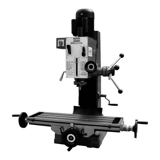
- Page 4 IDENTIFICATION Motor Spindle Speed Lever Switch Feed Handle Spindle Range Lever Micro Feed Handwheel Spindle Lock Lever Lock Handle Longitudinal Lock screw Rocker Cross Slide Handwheel Longitudinal Slide Handle...
-
Page 5: Section 1 : Safety
SECTION 1 : SAFETY For you own safety, read instruction manual be for operating this machine. As with all machinery, there are certain hazards involved with their operation and use. Exercising respect and caution will considerably lessen the risk of personal injury. - Page 6 SECTION 1 : SAFETY Additional Safety Rules For This Machine This machine must not be modified for any purpose other than that for which it designed. ● You should not operate this machine unless you are thoroughly familiar with metal turning lathes and turning techniques.
-
Page 7: Section 2 : Installation
SECTION 2 : INSTALLATION Installation 1. Ensure the headstock is as lower as possible, and be fixed on the column tightly before moving machine. while moving machine, keep its balance and safety. 2. Don’ t mount the machine at the sunshine place to avoid the deformity of machine and the loss of accuracy. -
Page 8: Section 3 : Operation
SECTION 3 : OPERATION Notice: Check all parts and safety precautions for proper condition before operation. Use of main machine parts Feed Handle (1) Raise and lower the headstock on its rack and pinion mechanism by using the head crank. when the desired height is reached, Lock Handle tighten the bolts to avoid vibration. - Page 9 SECTION 3 : OPERATION Milling operation (1) Adjust the positive stop depth gauge to its uppermost position. (2) Using the spindle feeding handle, adjust the cutter to approximately the correct height, turn off the knob make tighten the taper body of worm and spring base. (3) Set the working depth by using the micro feeding handle.
- Page 10 SECTION 3 : OPERATION Installing and changing tools Warning: Be sure the power is turned off and the machine unplugged before installing or changing tool bits (1) Removing face mill or drill chuck arbor. Loosen the arbor bolt at the top of the spindle shaft approximately 2 turns with a wrench.rap the top of the arbor bolt with a mallet.
- Page 11 SECTION 3 : OPERATION Electrical system 1. A fuse must be connected between machine and power. 2. The ground terminal of machine must be grounded properly. 3. D on’ t op en ele c t r ic al b o x dur ing operation, if something is wrong with machine, please ask repairman for help.
- Page 12 SECTION 3 : OPERATION Trouble shooting 1. The machine doesn’t run when the power switch is turned ON (a) The knob is in the STOP position (b) A fuse has burned out---Check in the switch box, and replace it necessary. (c) If there is a surge in the current, the circuit breaker may have opened---Press the circuit breaker back, if it is in the open position.
-
Page 13: Daily Maintenance
SECTION 3 : OPERATION Maintenance 1. After each use (a) Turn off the power switch. (b) Remove any tool bits, clean and lubricate them, and return them to their storage case. (c) Using a stiff bristle brush, brush off all chips. (d) Using a rag, wipe off any excess or dirty oil or cutting fluid left on the machine. -
Page 14: Section 4 : Accessories
SECTION 4 : Accessories Standard Accessories The parts have been removed from the box, you should have the following items: A. Handwheel..........3 B. Driving Screw..........1 C. Wrench (22-24)..........1 D. Hex Wrench Set(4,5,6,8).......1 EA Figure 12. Standard Accessories Optional Accessories End Mill Chuck Machine Vice Figure 13. -
Page 15: Section 5 : Parts
SECTION 5 : PARTS Headstock Diagram... -
Page 16: Headstock Parts List
SECTION 5 : PARTS Headstock Parts List PARTS DESCRIPTION ZX45DP001 Handle M6*32 JB/T7273.2-94 ZX45DP002 Handqheel 12*100 JB/T7270.4-94 ZX45DP003 Screw M5*8 GB/T77-85 ZX45DP004 Dial seat XZ32G-30-011 ZX45DP005 Screw M6*14 GB/T70-85 ZX45DP006 Screw M5*14 GB/T70-85 ZX45DP007 Cover XZ32G-30-009 ZX45DP008 Bearing spacer XZ32G-30-008 ZX45DP009 Bearing 6202 GB/T276-94... - Page 17 SECTION 5 : PARTS Headstock Parts List PARTS DESCRIPTION ZX45DP0051 Gear XZ32G-20-022 ZX45DP0052 Screw M5*8 GB/T73-85 ZX45DP0053 Shaft XZ32G-20-018 ZX45DP0054 5*60 GB/T1096-79 ZX45DP0055 6*12 GB/T1096-79 ZX45DP0056 Gear XZ32G-20-025 ZX45DP0057 Gear XZ32G-20-017 ZX45DP0058 6*28 GB/T1096-79 ZX45DP0059 Gear XZ32 G-20-007 ZX45DP0060 Shaft XZ32G-20-003 ZX45DP0061 6*75 GB/T1096-79...
- Page 18 SECTION 5 : PARTS Table Diagram...
- Page 19 SECTION 5 : PARTS Table Parts List PARTS DESCRIPTION ZX45TB001 Handle BM10×80 GB/T7270.4 ZX45TB002 Hand wheel XZ32 G-10-001 ZX45TB003 Screw M6×10 GB/T73-85 ZX45TB004 Dial clutch XZ32G-10-002 ZX45TB005 Spring pin 5×40 GB/T879-86 ZX45TB006 Dial ring XZ32G-10-044 ZX45TB007 Screw M8×16 GB/T70-85 ZX45TB008 Square flange XZ32G-10-003 ZX45TB009...
- Page 20 SECTION 5 : PARTS Table Parts List PARTS DESCRIPTION ZX45TB0041 Taper gear XZ32G-10-032 ZX45TB0042 Bearing 6204-2RS GB/T276-94 ZX45TB0043 Retain ring 20 GB/T894.1-86 ZX45TB0044 5×12 GB/T1096-79 ZX45TB0045 Screw XZ32G-10-022 ZX45TB0046 Screw M5×10 GB/T67-85 ZX45TB0047 Cover XZ32G-10-039 ZX45TB0048 Screw M8×40 GB/T70-85 ZX45TB0049 Connective base XZ32G-10-023 ZX45TB0050...
- Page 21 SECTION 5 : PARTS Spindle Diagram...
- Page 22 SECTION 5 : PARTS Spindle List PARTS DESCRIPTION ZX45SP001 Spindle XZ32G-21-001 ZX45SP002 Stop washer 30 GB/T858-88 ZX45SP003 M30×1.5 GB/T810-86 ZX45SP004 Bolt M6×50 GB/T5780-86 ZX45SP005 Graduate rod base XZ32G-21-003 ZX45SP006 M6 GB/T41-86 ZX45SP007 Anti-dust cover XZ32G-21-002 ZX45SP008 Bearing 30207/P6 GB/T297-94 ZX45SP009 Rack sleeve XZ32G-21-005 ZX45SP0010...
-
Page 23: Warranty
Warranty Bolton Tools Inc. warrants all Bolton Tools machinery to be free of defect from workmanship and materials for a period of one year from the date of original purchase by the original purchaser. This warranty does not apply to damage due directly or indirectly to misuse, lack of maintenance, abuse, negligence, accidents, repairs or alterations outside of our facilities.
Need help?
Do you have a question about the ZX45 and is the answer not in the manual?
Questions and answers