BFT Maxima Ultra 68 Installation And User Manual
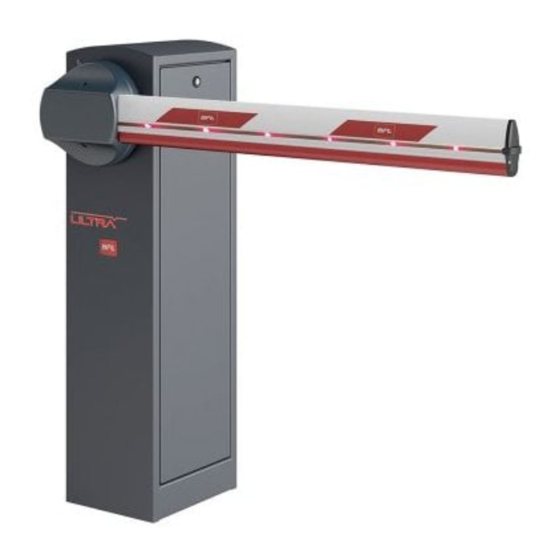
Automatic barrier
Hide thumbs
Also See for Maxima Ultra 68:
- Installation and user manual (36 pages) ,
- Instructions for installation, use and maintenance manual (12 pages) ,
- Instructions for installation manual (8 pages)
Table of Contents
Advertisement
BARRIERA AUTOMATICA
AUTOMATIC BARRIER
BARRIÈRE AUTOMATIQUE
AUTOMATISCHE SCHRANKE
BARRERA AUTOMÁTICA
Attenzione! Leggere attentamente le "Avvertenze" all'interno! Caution! Read "Warnings" inside carefully! Attention! Veuillez lire attentivement les Avertissements qui se trouvent à l'intérieur!
Achtung! Bitte lesen Sie aufmerksam die „Hinweise" im Inneren! ¡Atención¡ Leer atentamente las "Advertencias" en el interior! Let op! Lees de "Waarschuwingen" aan de binnenkant zorgvuldig!
Advertisement
Table of Contents

Related Manuals for BFT Maxima Ultra 68


Summary of Contents for BFT Maxima Ultra 68
- Page 1 BARRIERA AUTOMATICA AUTOMATIC BARRIER BARRIÈRE AUTOMATIQUE AUTOMATISCHE SCHRANKE BARRERA AUTOMÁTICA Attenzione! Leggere attentamente le “Avvertenze” all’interno! Caution! Read “Warnings” inside carefully! Attention! Veuillez lire attentivement les Avertissements qui se trouvent à l’intérieur! Achtung! Bitte lesen Sie aufmerksam die „Hinweise“ im Inneren! ¡Atención¡ Leer atentamente las “Advertencias” en el interior! Let op! Lees de “Waarschuwingen” aan de binnenkant zorgvuldig!
-
Page 2: Table Of Contents
Index 1. General information Align the arm ..............pag. 13 Introduction ..............pag. 10 Balancing the arm ............pag. 14 General safety ............... pag. 10 Optionals ................ pag. 14 General ................pag. 10 Electrical connections ..........pag. 14 Technical specifi cation ..........pag. 10 3. -
Page 3: General Information
1. General information 1.1 INTRODUCTION Please read it carefully before installing the appliance, before using it and before routine or extraordinary maintenance work. The notices preceded by this symbol provide important information, the non-compliance with such instructions voids the manufacturer’s guarantee. OPERATIONS THAT, IF NOT CARRIED OUT CORRECTLY, CAN BE RISKY, ARE INDICATED WITH THE FOLLOWING SYMBOLS ELECTROCUTION CRUSHING... -
Page 4: Overall Dimensions
1. General information / 2. Installation 1.5 OVERALL DIMENSIONS RIGHT barrier LEFT barrier 2.1 CABLE NOTE 1) Single-phase line 2 x 1,5 + E 2) Transmitter photocell 2 x 0,5 3) Receiver photocell 4 x 0,5 4) Flashing light 2 x 0,5 5) Key selector 3 x 0,5 6) Receiver... -
Page 5: Springs Mounting
2. Installation 2.3 SPRINGS MOUNTING If single spring, mount in position First mount spring if present. 17mm Do not tighten before the balancing arm (see point 2.6) Mount spring 17mm Do not tighten before the balancing arm (see point 2.6) - 12 -... -
Page 6: Instal The Arm
2. Installation 2.4 INSTALL THE ARM M16x100 Ø16 Ø6x16 Ø10 Ø8 M6x10 Ø10 Ø16 M10x25 Ø8 M8x20 M6x16 Ø6 Ø6 TIGHTEN 210Nm M6x16 M6x10 2.5 ALIGN THE ARM Electrically connect the control unit (see point 2.8) • Insert about 1 metre of the arm in the holder •... -
Page 7: Balancing The Arm
2. Installation Check that the bar is Give the “START” command to position Opening microswitch cam in vertical position the arm holder vertically 3 mm TO SET THE BOOM IN VERTICAL POSITION ADJUST THE OPEN LIMIT SWITCH CAM. 2.6 BALANCING THE ARM 45°... -
Page 8: Use And Maintenance
3. Use and maintenance GENERAL SAFETY • The barrier is designed exclusively for vehicles traffi c; report and delimit any walkways through a special sign. • Keep adults, children and property out of range of the automated system, especially while it is operating. •... - Page 9 REGISTRO DI MANUTENZIONE MAINTENANCE LOG Dati impianto • Installation data Installatore Installer Cliente Customer Matricola Serial number Data installazione Installation date Data attivazione Activation date Luogo Location Data • Date Descrizione intervento • Intervention description Firma • Signature Tecnico • Technician Cliente •...
- Page 10 INSTALLATORE INSTALLER INSTALLATEUR INSTALLATEUR INSTALATOR DATA DATE DATE DATUM FECHA ITALY...
Need help?
Do you have a question about the Maxima Ultra 68 and is the answer not in the manual?
Questions and answers