Table of Contents
Advertisement
Advertisement
Table of Contents

Related Manuals for Eurotherm P304c


Summary of Contents for Eurotherm P304c
- Page 1 P304c Melt Pressure Controller User Manual HA031861/3 Date July 2014...
-
Page 3: Table Of Contents
P304c Controller User Manual P304c Melt Pressure Controller User Manual Part Number HA031861 Issue 3 Date July 2014 Contents DESCRIPTION ............................3 Unpacking Your Controller ........................... 3 Dimensions ..............................3 Step 1: Installation ............................4 1.3.1 Panel Mounting the Controller ............................4 1.3.2... - Page 4 P304c Controller User Manual 3.11.4 Calibration of pressure transducer connected to the secondary input ..............27 CONTROLLER BLOCK DIAGRAM...................... 28 CONFIGURATION LEVEL ........................29 To Select Configuration Level ........................29 Configuration Level Parameters ......................... 29 Configuration - ‘P’ Codes ..........................30 5.3.1...
-
Page 5: Description
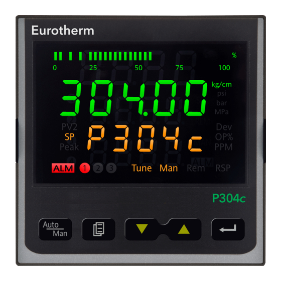
P304c Controller User Manual 1. Description P304c is a microprocessor based pressure and process controller based on the Piccolo range of instruments. It is suitable for use on a wide range of processes including the control and indication of extruder melt pressure. -
Page 6: Step 1: Installation
To ensure panel sealing, mount on a non-textured surface. Please read the safety information in section 2 before proceeding. An EMC Booklet, part number HA025464, gives further installation information and can be downloaded from www.eurotherm.co.uk. 1.3.1 Panel Mounting the Controller The instrument can be fitted into a panel up to 25mm thick. -
Page 7: Order Code
P304c Controller User Manual Order Code Model Number Function Supply Voltage Second Input Options Custom Label Special Model Number Function Power Supply P304c ¼ DIN controller Pressure controller 100 - 230Vac 50 / 60Hz 24Vac / Vdc Custom Label Second Input... -
Page 8: Step 2: Wiring
P304c Controller User Manual Step 2: Wiring 1.5.1 Rear Terminal Connections Primary Secondary Input Input 12 + SIG+ 56 + 13 - 57 - SIG- 58 + CAL2 59 - 16 + A/A’ EXC+ EXC- B/B’ SIG+ 17 - CAL1... -
Page 9: Power Supply
P304c Controller User Manual The specification given in the following sections are a summary only. For full specifications see section 11. 1.5.4 Power Supply Before connecting the instrument to the power line, make sure that the line voltage corresponds to the description on the identification label. -
Page 10: Sensor Inputs
P304c Controller User Manual 1.5.5 Sensor Inputs Precautions • Do not run input wires together with power cables • When shielded cable is used, it should be grounded at one point only • These inputs are isolated 1.5.5.1 Pressure Transducer - Primary Input/Secondary Input... -
Page 11: Transmitter Power Supply (Tpsu)
P304c Controller User Manual 1.5.5.4 mA - Primary Input/Secondary Input 17/3 • Ranges: 0-20mA, 4-20mA configurable • It is not necessary to fit a burden resistor to the mA inputs 18/4 since this is connected internally. 1.5.5.5 Voltage - Primary Input/Secondary Input 17/3 •... -
Page 12: Analogue Outputs
P304c Controller User Manual 1.5.7 Analogue Outputs Two analogue outputs are provided. OUT1 is used for control and OUT2 is used for retransmission of the measured value. Both outputs may be configured using the appropriate ‘P’ codes (section 5.3). 1.5.7.1 Control Output (OUT1) •... -
Page 13: Digital Inputs
P304c Controller User Manual 1.5.8 Digital Inputs • Four optional digital inputs are provided for control purposes plus one for reset purposes. • The interface circuit is opto-isolated with respect to the CPU, analogue inputs and outputs, but not isolated with respect to the EIA485 digital communications. -
Page 14: Alarms
P304c Controller User Manual 1.5.9 Alarms There are three standard alarms. Each alarm is: • Keyboard programmable using the appropriate ‘P’ codes for: - Process variable / Deviation / Band - High / Low / Low masked on start up - Auto / Manual reset - Hysteresis - adjustable from 0.1% to 10% of span or one LSD (whichever is the greater) -
Page 15: Modbus Serial Communications
P304c Controller User Manual 1.5.10 Modbus Serial Communications Digital communications uses the Modbus protocol EIA485 2-wire. Cable screen should be grounded at one point only to prevent earth loops. EIA485 Connections 220Ω termination resistor Twisted pair B/B’ A/A’ Common... -
Page 16: Safety And Emc Information
P304c Controller User Manual 2. Safety and EMC Information This instrument is intended for industrial temperature and process control applications within the requirements of the European Directives on Safety and EMC. Information contained here is subject to change without notice. While every effort has been made to ensure the accuracy of the information, your supplier shall not be held liable for errors contained herein. -
Page 17: Switch On
P304c Controller User Manual 3. Switch On Whenever the controller is switched on (powered up) it will start in a diagnostic mode lasting for a few seconds. The diagnostic display illuminates all bars of each character and every beacon, followed briefly by the firmware version number and the instrument type (P304c). -
Page 18: Example - To Display Selected Parameters
P304c Controller User Manual 3.1.3 Example – To Display Selected Parameters Press to select in turn SP, Dev, OP%, RPM, Peak. These are shown lower display and have the following meanings: The value of the setpoint is displayed. If Lr.SP in the Level 2 list = Loc, the local setpoint value (which is set by selecting SP in the Level 1 or Level 2 list) is displayed. -
Page 19: Level 1 Operation
P304c Controller User Manual Level 1 Operation At switch on the instrument enters Level 1. Press to scroll through a list of parameters available in this level. Press to adjust an analogue value or a digital enumeration, provided that the parameter is not read only or has been locked in other levels. -
Page 20: Example 2 - To Adjust The Output Level In Manual Mode
P304c Controller User Manual 3.4.3 Example 2 – To Adjust the Output Level in Manual Mode The output voltage or current can be raised or lowered manually. See also section 3.8. Select Manual Mode. This can be done in one of two ways: Auto 1. -
Page 21: Level 2 Operation
P304c Controller User Manual Level 2 Operation Level 2 parameters also include Level 1 parameters. To select a parameter:- Press to scroll through a list of parameters. Press to adjust an analogue value or a digital enumeration, provided that the parameter is not read only or has been locked in configuration level. - Page 22 P304c Controller User Manual Mnemonic Parameter Availability Notes Further Information Shown in the lower display A3.HS ALARM 3 HYSTERESIS If P69 ≠ OFF Range 0.1 to 10.0%. Default = 1.0. Pi.vAL PRIMARY PRESSURE INPUT Only if P11 See ‘Level 1 Parameters’...
-
Page 23: To Return To Level 1
P304c Controller User Manual At.iP AUTOMATIC SELECTION OF Setting this parameter to Auto causes the controller to THE INTEGRAL PRE LOAD calculate the integral pre load value using the set point VALUE and process gain values. The process gain value is estimated during the auto tuning function, then the automatic calculation of the integral pre load value is reliable only after a tuning trial. -
Page 24: Auto / Manual Mode
P304c Controller User Manual Auto / Manual Mode Auto mode is the normal operation where the output is adjusted automatically by the controller in response to changes in the measured value (pressure). In Auto mode all the alarms and the other functions are operational. -
Page 25: Alarms
P304c Controller User Manual Alarms Alarms are used to alert an operator when a pre-set level has been exceeded. The threshold value can be set in Level 1 (or 2) by the alarm setpoint parameters AL1, AL2 or AL3. , etc. -
Page 26: Band High
P304c Controller User Manual 3.10.3 Band High This alarm is used to indicate when the PV is outside the normal working high and low range. Example: Alarm 1 = Band High (bAnd set by P61 and HI set by P62). -
Page 27: Deviation High
P304c Controller User Manual 3.10.5 Deviation High The controller will indicate an alarm if the error value exceeds a high limit set by the alarm threshold. Example: Alarm 1 = Deviation High (dEv set by P61 and HI set by P62). -
Page 28: Alarm Mask At Start Up
P304c Controller User Manual 3.10.7 Alarm Mask at Start up Alarm mask at start up is used to inhibit the activation of an alarm during start up of the process. When the process has reached steady state conditions and has achieved the safe state defined by the alarm threshold the mask is removed. -
Page 29: Pressure Transducer Calibration
P304c Controller User Manual 3.11 Pressure Transducer Calibration This section describes how to calibrate the instrument to the particular pressure transducer being used. The instrument should be powered up for at least 15 minutes and allow the transducer to reach operating conditions. -
Page 30: Controller Block Diagram
P304c Controller User Manual 4. Controller Block Diagram The block diagram shows the function blocks which make up the controller. Where applicable, each block is represented by the ‘P’ code as described in the section 5. Inputs Processes Outputs Primary... -
Page 31: Configuration Level
P304c Controller User Manual 5. Configuration Level Configuration of the controller is carried out using a list of ‘P’ codes. Each P code is associated with a particular feature of the controller such as Input Type, Ranging, Control Type, Outputs, Alarms, Digital Communications, Calibration, etc. -
Page 32: Configuration - 'P' Codes
P304c Controller User Manual Configuration - ‘P’ Codes Use these codes to configure the controller to meet the requirements of the process. 5.3.1 Summary This section gives an overview of the ‘P’ codes. Pressure input selection Alarm 1 input channel link... -
Page 33: Pressure Input Selection
P304c Controller User Manual 5.3.2 Pressure Input Selection Code Description Range Configures the Type of Pressure Input. Strain gauge (default) Note: Remember to properly wire the unit’s terminal block 0-20 0-20 mA 4-20 mA 4-20 0-5V 0-10 0-10V. Configures the Pressure Input Engineering Unit... -
Page 34: Secondary Input
P304c Controller User Manual 5.3.5 Secondary Input Code Description Range Configures the Secondary Input Type Disabled Remember to properly wire the unit’s terminal block. 0-20 0-20mA 4-20 4-20mA (default) 0-5 Volts 0-10 0-10 Volts Strain Gauge Configures the Function of the Secondary Input... -
Page 35: Control Output
P304c Controller User Manual 5.3.6 Control Output The control output is an analogue output and is always OUT1 on terminals 21 and 22 Code Description Range Configures the Type of control output. 0-20 0-20mA Remember to wire the terminal block correctly. -
Page 36: Retransmission
P304c Controller User Manual 5.3.7 Retransmission The measured pressure can be retransmitted as an analogue value on OUT2, terminals 56 and 57. Code Description Range Configures the Type of Retransmission Disabled Available only if the retransmission circuit is fitted. 0-20... -
Page 37: Alarms
P304c Controller User Manual 5.3.8 Alarms Up to three alarms can be configured. They are used to detect out of range values. Code Description Range Configures the Alarm 1 selection. Disabled Process alarm (default) All alarms can be attached to the measured pressure,... -
Page 38: Logic Input
P304c Controller User Manual 5.3.9 Logic Input The Logic Input is fitted as standard and can be configured as a reset for alarms or peak detection, or it can be used to externally select the pressure transducer calibration. It is a contact closure input but is edge triggered on contact closure. -
Page 39: Manual/Auto Start-Up
P304c Controller User Manual 5.3.12 Manual/Auto Start-Up Code Description Range Configures the Controller status at power on. AUto Automatic closed loop control The controller can be made to start up in Manual mode Manual control (default) (power output demanded manually) or Automatic – power output controlled in closed loop. -
Page 40: Digital Communications
P304c Controller User Manual 5.3.13 Digital Communications Digital communications is orderable. It uses Modbus or Jbus protocol and EIA485 2-wire interface . Code Description Range Configures the Serial communication interface address. Disabled (default) 1 to 255 An address of 1 to 255 can... -
Page 41: Pass Codes
P304c Controller User Manual 5.3.14 Pass codes Pass codes are required to enter both Operator Level 2 and Configuration Level. They are set to default values during manufacture but they can be re-configured using P98 and P99. Code Description Range Configures the Level 2 pass code. -
Page 42: Control
P304c Controller User Manual 6. Control This section shows an example of how the control loop operates and how it may be used to control the melt pressure in an extrusion process. The actual melt pressure (PV) is measured by the transducer which is connected to the input of the controller. -
Page 43: Integral Term 'Ti
P304c Controller User Manual The diagram also shows the effect of narrowing proportional band to the point of oscillation. A very wide proportional band results in straight line control but with an appreciable initial error between setpoint and PV. As the band is narrowed the PV gets closer to setpoint. If the proportional band is very narrow the loop becomes unstable resulting in an oscillatory response. -
Page 44: Tuning
Start up of a Process The P304c allows a process to be started in Manual or Automatic mode. The default is Manual since most of the applications for which this instrument is designed is for extruder melt pressure control which modifies the motor speed to control the pressure. -
Page 45: Digital Communications
Appendix 10. EIA485 Field Communications Port To use EIA485, buffer the EIA232 port of the PC with a suitable EIA232/EIA485 converter. The Eurotherm KD485 Communications Adapter unit is recommended for this purpose. The use of a EIA485 board built into the computer is not recommended since this board may not be isolated, which may cause noise problems, and the RX terminals may not be biased correctly for this application. -
Page 46: Instrument Calibration
P304c Controller User Manual 8. Instrument Calibration The controller is calibrated during manufacture using traceable standards for every input and output range. It is, therefore, not necessary to calibrate it when changing ranges. Furthermore, the use of a continuous automatic zero correction of the input ensures that the calibration of the instrument is optimised during normal operation. - Page 47 P304c Controller User Manual Parameter Circuit Input/output Type Range Value Note S .Pt5 Secondary input RTD-Pt500 Verify NL.Cur Main analogue output OUT1 Current Zero -5mA NH.Cur Main analogue output OUT1 Current Full scale 25mA Main analogue output OUT1 Current Verify N .Cur...
-
Page 48: Error Codes
P304c Controller User Manual Error Codes The following error codes could be displayed:- Code Meaning Error during EEPROM access. The TUNE (auto tune) function is not able to apply the step change because the manual output value plus the step... -
Page 49: Example 1: To Calibrate The 0-10V Main Input
P304c Controller User Manual Example 1: To Calibrate the 0-10V Main Input Connect a calibrated voltage source the main input terminals as shown. 17 - P304c Voltage Copper cable Controller Source 19 + Action Display Notes Press to scroll to the low calibration O F F point for the 0-10V main input, PL.010... -
Page 50: Example 2: To Calibrate The 0-5V Main Input
P304c Controller User Manual Example 2: To Calibrate the 0-5V Main Input Connect a calibrated voltage source the main input terminals as shown. 17 - P304c Voltage The procedure is the same as for the above Copper cable Source Controller... -
Page 51: Example 3: To Calibrate The 0-20Ma Main Input
P304c Controller User Manual Example 3: To Calibrate the 0-20mA Main Input Connect a calibrated voltage source the main input terminals as shown. 17 - P304c The procedure is the same as for the above Copper cable Controller Source example but uses different parameters and 19 + voltage values. -
Page 52: Example 4: To Calibrate The Control Output (Out1) - Voltage
P304c Controller User Manual Example 4: To Calibrate the Control Output (OUT1) - Voltage The example is given for 0-10V output. Connect a calibrated volt meter to the retransmission output 20.00 21 + terminals 21 and 22. 22 - Digital Voltmeter... -
Page 53: Cpi (Configuration Port Interface)
Do not use this port for any other purposes. CPI Adaptor A choice of two configuration clips is available from Eurotherm either of which may be ordered as part of the iTools configuration package or as a separate item: 1. USB CPI Clip which may be ordered quoting part number IToolsNONE-USB. -
Page 54: Firmware Update Procedure
P304c Controller User Manual Firmware Update Procedure The firmware code is stored in a rewritable Flash memory and it can be updated following the below procedure. Required tools: • A PC with serial COM port or with an USB to Serial adapter. -
Page 55: Appendix A Modbus And Jbus Addresses
P304c Controller User Manual 10. Appendix A Modbus and Jbus Addresses 10.1 Multiplier and Decimal figures Some parameters have a related variable stated as “multiplier”; this system allows the limits of +/- 32767 counts to be overcome. Example: the measured value 80000 is sent as 1600 and a multiplier of 50. - Page 56 P304c Controller User Manual Mnem. Parameter Modbus Jbus Range Pi.vAL PRIMARY PRESSURE INPUT 1114 1115 Note: VALUE When an error is detected on measure the "data" field contains one of these error codes: 30002 (7532h): Open 30003 (7533h): Wrong zero measure...
- Page 57 P304c Controller User Manual Mnem. Parameter Modbus Jbus Range 1: function enabled ASb.PL AUTOMATIC STAND-BY 1224 1225 PRESSURE LOW LIMIT ASb.rT AUTOMATIC STAND-BY 1225 1226 61: no timeout applied RECOVERY TIME A1.FL ALARM 1 FILTER 1217 1218 0 = 0 s (no filter) 1 = 0.4 s...
- Page 58 P304c Controller User Manual Configuration Parameters Code Description Modbus Jbus Range PRESSURE INPUT 1500 1501 0 = strain gage SELECTION 1 = 0-20 mA 2 = 4-20 mA 3 = 0-5 V 4 = 0-10 V PRESSURE INPUT 1339 1340...
- Page 59 P304c Controller User Manual SCALE VALUE SECONDARY INPUT LOW 1341 1342 SCALE VALUE SECONDARY INPUT FAIL 1404 1405 0 = high SAFE 1 = low REMOTE SET POINT INPUT 1304 1305 RANGE LOW REMOTE SET POINT INPUT 1305 1306 RANGE HIGH...
- Page 60 P304c Controller User Manual ALARM 3 TYPE 1316 1317 As P62 ALARM 3 RESET MODE 1411 1412 As P63 ALARM 3 FAILSAFE MODE 1425 1426 As P64 LOGIC INPUT 1413 1414 0 = input disabled CONFIGURATION 1 = alarm reset...
- Page 61 P304c Controller User Manual 10.4 Other Parameters Code Description Modbus Jbus Range Alarm 1 Status 1008 1009 0: no alarm condition 1: alarm condition Alarm 2 Status 1009 1011 Alarm 3 Status 1011 1012 Auto/manual selection 1104 1105 0 = selection from front panel or serial communication...
-
Page 62: Appendix B Technical Specification
P304c Controller User Manual 11. Appendix B TECHNICAL SPECIFICATION General Power Supply requirements High voltage 100 to 230Vac, +/-15% Environmental performance 50 to 60Hz Temperature Operation: 0 to 50°C (32 to 122°F), Low voltage 24Vac, (14 to 32Vac) 50/60Hz limits Storage: -20 to 70°C (-4 to 158°F) - Page 63 P304c Controller User Manual • Strain gauge from 340 to 5000 ohm, 1-4 mV/V. -10/+10 VDC min. load 5 kohm input Excitation 10V +/- 7%. 5 wire connection. • 0/5 VDC min. load 5 kohm Interfacing 1mV/V sensors could worsen •...
-
Page 64: Index
P304c Controller User Manual 12. Index Alarms AUTOMATIC STAND-BY PRESSURE LOW LIMIT 20, 42 Band ................. 24 AUTOMATIC STAND-BY RECOVERY TIME ....20 Deviation ................. 25 CONTROL OUTPUT LIMITER......... 20 DERIVATIVE TIME ............20 Process ................23 Alarms: ..................23 FILTER FOR DISPLAY AND CONTROLLER .... - Page 66 All rights are strictly reserved. Reproduction, distribution or storage of this document in any manner is prohibited without prior written consent from Eurotherm. Information in this document may change without notice and is intended for guidance only. Eurotherm will accept no responsibility for any loses arising from errors in this document.
Need help?
Do you have a question about the P304c and is the answer not in the manual?
Questions and answers