
Subscribe to Our Youtube Channel
Related Manuals for Campbell RF407 Series


Summary of Contents for Campbell RF407 Series
- Page 1 RF407-Series Spread Spectrum Radios Revision: 1/18 C o p y r i g h t © 2 0 0 1 - 2 0 1 8 C a m p b e l l S c i e n t i f i c , I n c .
- Page 4 (780) 454-2655. Campbell Scientific (Canada) Corp. is unable to process any returns until we receive this form. If the form is not received within three days of product receipt or is incomplete, the product will be returned to the client at the client’s expense.
- Page 5 Periodically (at least yearly) check electrical ground connections. WHILE EVERY ATTEMPT IS MADE TO EMBODY THE HIGHEST DEGREE OF SAFETY IN ALL CAMPBELL SCIENTIFIC PRODUCTS, THE CLIENT ASSUMES ALL RISK FROM ANY INJURY RESULTING FROM IMPROPER INSTALLATION, USE, OR MAINTENANCE OF TRIPODS, TOWERS, OR ATTACHMENTS TO TRIPODS AND TOWERS SUCH AS SENSORS, CROSSARMS, ENCLOSURES, ANTENNAS, ETC.
- Page 6 PLEASE READ FIRST About this manual Please note that this manual was originally produced by Campbell Scientific Inc. (CSI) primarily for the US market. Some spellings, weights and measures may reflect this origin. Some useful conversion factors: Area: 1 in...
-
Page 8: Table Of Contents
Compatible Antennas ..............8 7.7.2 Electrostatic Issues and Surge Protection ........9 7.7.3 Antenna Cables ................10 8. Configuring the RF407 Series ......... 10 DevConfig ..................10 9. LoggerNet Setup ............11 Basic Setup..................11 Using a Repeater ................15 10. - Page 9 Table of Contents 11.1.1 Active Interface ................17 11.1.2 SDC Address ................18 11.1.3 RS-232 Baud Rate ..............18 11.1.4 Protocol ..................18 11.1.5 RF Hop Sequence ............... 18 11.1.6 Network ID ................19 11.1.7 Power Mode ................19 11.1.8 Retry Level ................. 19 11.1.9 Radio TX Power Level ...............
- Page 10 Table of Contents 7-3. RS-232 Pinout (9-PIN D-SUB FEMALE) ........... 8 B-1. Transmitter Power ................B-3 B-2. Cable Loss ..................B-4 B-3. LMR-195 Cable Loss vs. Length @ 900 MHz ........ B-4 B-4. Antenna Gain of Recommended Antennas ........B-4 B-5.
- Page 11 Table of Contents...
-
Page 12: Introduction
Keep RS-232, CS I/O, and USB connections short or use protective isolation and surge protection when appropriate. Where an AC adapter is used, Campbell Scientific recommends pn 15966. • Any other AC adapter used must have a DC output not exceeding 16 volts measured without a load to avoid damage to the radio. -
Page 13: Quickstart
• Thoroughly check all packaging material for product that may be trapped. Contact Campbell Scientific immediately about any discrepancies. Model numbers are found on each product. On cables, the model number is often found at the connection end of the cable. -
Page 14: Overview
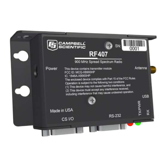
RF407-Series Spread Spectrum Radio Overview Spread-spectrum radios spread the normally narrowband information signal over a relatively wide band of frequencies. This allows the communications to be more immune to noise and interference from RF sources such as pagers, cellular phones, and multipath. The RF407-series radios reduce susceptibility to RF interference from other spread-spectrum devices by providing user- selectable frequency-hopping patterns. - Page 15 RF407-Series Spread Spectrum Radio LBT + AFA Compliance and Performance Complies with ETSI duty cycle requirements. Radio communication effective duty cycle = (number of channels • 100) / 3600. Channel Spacing: 100 kHz Receiver Bandwidth: 150 kHz Modulation Bandwidth: < 300 kHz LBT Threshold: <...
-
Page 16: Product Description
CAUTION There are many AC adapters available with barrel connectors that will fit the RF407 series. Damage that occurs from the use of an AC adapter that is not the 15966 AC to DC power adapter will not be covered by warranty. If using a different AC adapter, be sure that the adapter’s “no... -
Page 17: Cs I/O
Campbell Scientific datalogger using the supplied SC12 cable. This connection is used for power and data. The CS I/O port is not a typical RS-232 connection and is specific to Campbell Scientific products. CS I/O cannot be used for radio configuration using DevConfig. -
Page 18: Cs I/O Pinout ( 9-Pin D-Sub Male)
Sources 12 Vdc to power peripherals datalogger Serial data transmit line I = Signal into the RF407 series, O = Signal out of the RF407 series RS-232 The RS-232 port is a DCE, 9-pin female D-Sub connector used to for connecting the radio to the RS-232 port of a datalogger, computer, or another RS-232 device. -
Page 19: Leds
RF407-Series Spread Spectrum Radio TABLE 7-3. RS-232 Pinout (9-PIN D-SUB FEMALE) Description I = Signal into the RF407 series, O = Signal out of the RF407 series LEDs The radios have a red LED labeled TX/PWR and a green LED labeled RX. -
Page 20: Electrostatic Issues And Surge Protection
CAUTION In order to comply with the FCC RF exposure requirements, the RF407 series may be used only with approved antennas that have been tested with these radios and a minimum separation distance of 20 cm must be maintained from the antenna to any nearby persons. -
Page 21: Antenna Cables
Series under Device Type. Click the Install the USB device driver link and follow the prompts. Open DevConfig. Under Device Type, select Radio | RF407 Series. Carefully review the Connect Instructions text provided on the right. With the USB device driver installation complete, connect the supplied USB cable between the USB port on your computer and the USB port on the radio. -
Page 22: Loggernet Setup
RF407-Series Spread Spectrum Radio You will be prompted to save your configuration. Doing so will allow you to easily recall the configuration later or apply this same configuration to other devices. LoggerNet Setup Basic Setup Start LoggerNet and open the Setup screen from the Main category of the toolbar. - Page 23 RF407-Series Spread Spectrum Radio With the setup tree entered, you will now need to complete the configuration of each element. Start with selecting the ComPort element at the root of the tree. Under ComPort Connection, select port labeled RF407-Series.
- Page 24 RF407-Series Spread Spectrum Radio Select the PakBusPort element in the tree, and select the PakBus Port Always Open checkbox. Set the Maximum Baud Rate to 115200.
- Page 25 RF407-Series Spread Spectrum Radio Finally, select your datalogger in the tree. Set the PakBus Address field to the address of your datalogger. Enter the Security Code, if security has PakBus ® been set up in your datalogger. Press the Apply button to save your changes. You are now ready to connect to your datalogger using the LoggerNet Connect screen.
-
Page 26: Using A Repeater
PakBus ® address of the RF407 series in the PakBus Address field. If the repeater is the first hop from LoggerNet, it should always be shown in the network map. This will force routes to go through the repeater. If the repeater is further down the network, it may still be helpful to display it in the network map. -
Page 27: Antenna Selection, Placement, And Mounting
RF407-Series Spread Spectrum Radio and urban areas tend to evolve over time meaning new sources of interference may develop over time. 10.2 Antenna Selection, Placement, and Mounting Antenna selection and placement can play a large role in system performance. Often directional antennas are preferred over omnidirectional antennas when possible as RF energy can be more selectively directed and received and higher gains can be realized without the consumption of additional power. -
Page 28: Main
PakBus Node. Also ensure that PakBus Address is unique within the PakBus network. Use this setting only under special circumstances where the CS I/O port is connected to another Campbell Scientific peripheral configured for Modem Enable (ME) through an A100 Null Modem Adapter. The... -
Page 29: Sdc Address
RF407-Series Spread Spectrum Radio 11.1.2 SDC Address Specifies the CS I/O port SDC address when Active Interface is set as CS I/O SDC. 11.1.3 RS-232 Baud Rate Specifies the baud rate that will be used on the RS-232 port when Active Interface is set as RS-232. -
Page 30: Network Id
RF407-Series Spread Spectrum Radio 11.1.6 Network ID Specifies the RF network. This setting must match in all radios in the same RF network. Valid entries are 0 to 32767. 11.1.7 Power Mode Power Mode governs the duty cycle that the radio will use for powering its receiver. -
Page 31: Radio Tx Power Level
RF407-Series Spread Spectrum Radio transmission. When an RF packet fails to be acknowledged by the destination, the radio will delay a random amount of time before resending the packet again. A receiving radio responds to the sending radio with an ACK packet for every radio packet it receives addressed to it with a valid CRC. -
Page 32: Pakbus Beacon Interval
Central Router. A valid setting is a single address between 1 and 4094. When set, the RF407 series will act as a branch router. Specifying a central router address can reduce the amount of PakBus RF traffic by eliminating the exchange of neighbor lists with routers beyond the central router. -
Page 33: Advanced
RF407-Series Spread Spectrum Radio Example: (129,129) (1084, 1084) In the example above, nodes 129 and 1084 are assigned as neighbors to the RF407 series. 11.3 Advanced 11.3.1 Radio MAC Address The radio MAC Address. 11.3.2 Available Frequencies This read-only setting shows a bit field of the frequencies that are available in the modules’... -
Page 34: Operating System Version
DevConfig. Under the Main tab, set the Protocol to PakBus Node. This setting makes the RF407 an independent device in the network. The RF407 series must also be given a unique PakBus Address under the PakBus tab. This will prevent communication errors with other devices in the network and provide an address for a datalogger to query. -
Page 35: Battery Voltage
DevConfig. Under the Main tab, set the Protocol to PakBus Node. This setting makes the RF407 an independent device in the network. The RF407 series must also be given a unique PakBus Address under the PakBus tab. The RSSI and radio settings can be remotely accessed for any RF407 node displayed in PakBus Graph. -
Page 36: Attributions
RF407-Series Spread Spectrum Radio 12. Attributions PakBus is a registered trademark of Campbell Scientific, Inc. PolyPhaser is a registered trademark of Transtector Systems, Inc. Windows is a registered trademark of Microsoft. - Page 37 RF407-Series Spread Spectrum Radio...
-
Page 38: Part 15 Fcc Compliance Warning
Warning Changes or modifications to the RF407-series radio systems not expressly approved by Campbell Scientific, Inc. could void the user’s authority to operate this product. Note: This equipment has been tested and found to comply with the limits for a Class B digital device, pursuant to part 15 of the FCC Rules. -
Page 40: Distance Vs. Antenna Gain, Terrain, And Other Factors
Gain, Terrain, and Other Factors B.1 Introduction The communication distance you can expect to obtain using the RF407 series depends on a number of factors that are unique to every installation. These unique factors are the path of propagation, relative antenna elevations, and the link budget. -
Page 41: How Far Can You Go
In some cases, an in-line RF amplifier may be used to provide additional system gain, but this is rare and not typical of Campbell Scientific installations. Losses derive from the attenuation of the RF signal as it propagates through the transmission lines (coaxial cables, surge suppressor, etc.) connecting the... -
Page 42: Transmitter Power
(Pt) and transmitter power in dBm (Ptx) is: Ptx (in dBm) = 10 log (Pt) with Pt expressed in mW TABLE B-1. Transmitter Power Transmitter Power (Pt) (milliWatts) 5 (RF407 series minimum) 250 (RF407 series maximum) 1000 5000 B.2.4 Cable Loss Cable loss is a function of cable type, length, and frequency and is usually specified as attenuation (dB) per 100 ft. -
Page 43: Antenna Gain
(decibels of gain relative to a dipole). The relationship is: dBi = dBd + 2.15 Some antennas that are FCC approved for use with the RF407 series are: TABLE B-4. Antenna Gain of Recommended Antennas CSI Part Mfg. -
Page 44: Receiver Sensitivity
Appendix B. Distance vs. Antenna Gain, Terrain, and Other Factors B.2.6 Receiver Sensitivity Receiver sensitivity is usually specified in dBm for a specific bit error rate (BER). The transceiver module used in the RF407 series is specified at –101 dBm at ~10 –4 raw BER. - Page 45 Appendix B. Distance vs. Antenna Gain, Terrain, and Other Factors and interferes with the main signal. This phenomenon gives rise to the 2-Ray Multipath Propagation Model for estimating real world distances. The path geometry defined by the relative elevations of the antennas and the distance between the antennas is a significant factor in determining the degree of interference from the reflected wave.
-
Page 46: Examples
Appendix B. Distance vs. Antenna Gain, Terrain, and Other Factors B.4 Examples Some examples will help illustrate the trade-offs in a link analysis. These examples will all use the RF407-series 900 MHz radio at maximum transmitter power, 24 dBm, and will use –101 dBm as the required power level at the radio receiver. - Page 47 Appendix B. Distance vs. Antenna Gain, Terrain, and Other Factors Using the Lpath values from TABLE B-8, gives: TABLE B-9. Fade Margin (dB) vs. Distance for 2-Ray Propagation Model in Example #1 Path Type 2 mi. 4 mi. 6 mi. 8 mi.
- Page 48 Appendix B. Distance vs. Antenna Gain, Terrain, and Other Factors Fade margin = 141 – Lpath Using the Lpath values from TABLE B-10, gives: TABLE B-11. Fade Margin (dB) vs. Distance for 2-Ray Propagation Model in Example #2 Path Type 2 mi.
- Page 49 Appendix B. Distance vs. Antenna Gain, Terrain, and Other Factors B-10...
- Page 51 Santo Domingo, Heredia 40305 SOUTH AFRICA COSTA RICA • cleroux@csafrica.co.za • info@campbellsci.cc www.campbellsci.co.za www.campbellsci.cc Campbell Scientific Southeast Asia Co., Ltd. Campbell Scientific Ltd. 877/22 Nirvana@Work, Rama 9 Road Campbell Park Suan Luang Subdistrict, Suan Luang District 80 Hathern Road Bangkok 10250...
Need help?
Do you have a question about the RF407 Series and is the answer not in the manual?
Questions and answers