Table of Contents
Advertisement
Quick Links
Advertisement
Table of Contents

Subscribe to Our Youtube Channel
Related Manuals for Campbell RF407 Series


Summary of Contents for Campbell RF407 Series
- Page 1 Revision: 11/2022 Copyright © 2001 – 2022 Campbell Scientific CSL I.D - 1143...
- Page 2 Quotations for repairs can be given on request. It is the policy of Campbell Scientific to protect the health of its employees and provide a safe working environment, in support of this policy a “Declaration of Hazardous Material and Decontamination”...
- Page 3 Note: raising the antenna is generally beneficial when trying to achieve maximum range. About this manual Please note that this manual was originally produced by Campbell Scientific Inc. primarily for the North American market. Some spellings, weights and measures may reflect this origin.
- Page 4 • Periodically (at least yearly) check electrical ground connections. WHILE EVERY ATTEMPT IS MADE TO EMBODY THE HIGHEST DEGREE OF SAFETY IN ALL CAMPBELL SCIENTIFIC PRODUCTS, THE CUSTOMER ASSUMES ALL RISK FROM ANY INJURY RESULTING FROM IMPROPER INSTALLATION, USE, OR MAINTENANCE OF TRIPODS, TOWERS, OR ATTACHMENTS TO TRIPODS AND TOWERS...
-
Page 5: Table Of Contents
Table of contents 1. Radio communications 1.1 Overview 1.2 Configuration options 2. Precautions 3. Initial inspection 4. QuickStart – Basic networks 4.1 Configure the base RF407-series radio 4.2 Configure the remote RF407-series data logger(s) 5. Specifications 6. Product description 6.1 Mounting 6.2 Power 6.3 USB 6.4 CS I/O... - Page 6 8.4 Using additional communications methods 9. Installation best practices 9.1 Avoiding interference 9.2 Antenna selection, placement, and mounting 9.3 Antenna cables 9.4 Troubleshooting 10. RF407-series radio settings 10.1 RadioAvailFreq 10.2 RadioChanMask 10.3 RadioEnable 10.4 RadioHopSeq 10.5 RadioMAC 10.6 RadioModel 10.7 RadioModuleVer 10.8 RadioNetID 10.9 RadioProtocol 10.10 RadioPwrMode...
-
Page 7: Radio Communications
1. Radio communications The RF407-series frequency-hopping spread-spectrum (FHSS) radio options include the RF407, RF412, RF422, and RF427. RF407-series are designed for license-free use in several countries: The RF407 option has a 902 to 928 MHz operating-frequency range appropriate for use in the United States and Canada (FCC / IC compliant). -
Page 8: Overview
1.1 Overview Spread-spectrum radios spread the normally narrowband information signal over a relatively wide band of frequencies. This allows the communications to be more immune to noise and interference from RF sources such as pagers, cellular phones, and multipath signals. The RF407- series radios reduce susceptibility to RF interference from other spread-spectrum devices by providing user-selectable frequency-hopping patterns. -
Page 9: Precautions
RS-232, CS I/O, and USB connections short or use protective isolation and surge protection when appropriate. A Campbell Scientific wall charger is recommended when AC power is used. Any other AC adapter used must have a DC output not exceeding 16 volts measured without a load to avoid damage to the radio. -
Page 10: Initial Inspection
File damage claims with the shipping company. Immediately check package contents against shipping documentation. Thoroughly check all packaging material for product that may be trapped. Contact Campbell Scientific immediately about any discrepancies. Model numbers are found on each product. On cables, the model number is often found at the connection end of the cable. - Page 11 1. Ensure that an antenna is connected to the RF407-series radio. 2. If connecting via USB for the first time, you must first install USB drivers using Device Configuration Utility (select your radio, then on the main page, click Install USB Driver). 3.
-
Page 12: Configure The Remote Rf407-Series Data Logger(S)
5. On the Main tab, set the Active Interface to USB or RS-232 (depending on how your computer will be connected to the RF407-series radio). 6. Apply to save your changes. 7. Close Device Configuration Utility. 8. The TX/PWR and RX LEDs flash once, after which the TX/PWR LED returns to blinking at the Power Mode interval (0.5 sec, by default). - Page 13 NOTE: Most Campbell Scientific devices come from the factory with a default PakBus address of 1. For this reason, it is best not to assign PakBus address 1 to any device in the network. Then, if a new device with default settings is added to the system, it will not create a conflict.
- Page 14 4. Using data logger support software, launch the EZSetup Wizard. LoggerNet users, from the Main category click Setup and select the View menu to ensure you are in the EZ (Simplified) view, then click Add PC400 users, click Add Datalogger 5. Click Next. 6.
-
Page 15: Specifications
10. In Configure the base RF407-series radio (p. 4) you selected an active interface option of USB or RS-232. If you selected USB as the active interface for the radio, you do not need to select a baud rate. If you selected RS-232, set the baud rate to the one chosen during that step. - Page 16 Transmit Power Output (software selectable) RF407 and RF412: 5 to 250 mW RF422: 2 to 25 mW RF427: 5 to 250 mW Channel Capacity RF407: Eight 25-channel hop sequences sharing 64 available channels. RF412: Eight 25-channel hop sequences sharing 31 available channels. RF422: Ten 30-channel hop sequences (default), software configurable to meet local regulations;...
- Page 17 RF422: LBT + AFA compliance and performance Complies with ETSI duty cycle requirements. Radio communications effective duty cycle = (number of channels × 100) / 3600. Channel spacing: 100 kHz Receiver bandwidth: 150 kHz Modulation bandwidth: < 300 kHz LBT threshold: < –88 dBm TX on time: <...
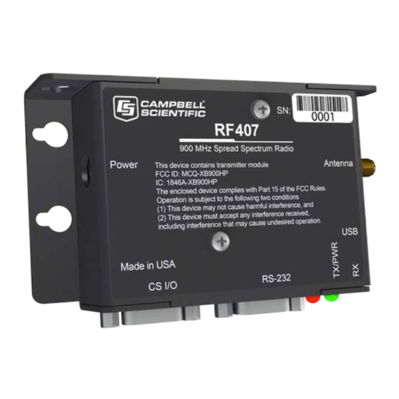
- Page 18 Diagnostics LEDs: TX/PWR (transmit/power), RX (receive) Received signal strength indicator (RSSI) for last packet Operating temperature Standard: –40 to 70 °C Configuration Device Configuration Utility via USB Compliance RF407: United States FCC Part 15.247: MCQ-XB900HP View the Declaration of Conformity at www.campbellsci.eu/rf407 Industry Canada (IC): 1846A-XB900HP Mexico Federal Telecommunications Institute...
-
Page 19: Product Description
The mounting holes are designed to align with a one-inch-on-center hole pattern and provide for either vertical or horizontal mounting. #6-32 x 0.375-inch stainless steel Phillips head screws and nylon grommets are supplied for securing the radio to the backplate of a Campbell Scientific enclosure. -
Page 20: Cs I/O
You will need the device driver properly installed before you can connect to the radio via USB. To install the device driver, download the latest version of Device Configuration Utility from our website. Under Device Type, select Radio > RF407 Series. Click Install USB Driver and follow the prompts. -
Page 21: Rs-232
DCE device, such as a data logger RS-232 port, MD485, or cellular modem, by using a 9- pin null-modem serial cable. When using RS-232, supply 12 VDC power to the Power connector by using a Campbell Scientific Field Power Cable or AC power adapter. The Active Interface setting must be set to RS-232, and the RS-232 port configuration, like baud rate, should match the device the radio is connected to. -
Page 22: Leds
6.7.1 Compatible antennas Campbell Scientific offers antennas to satisfy the needs for various base station and remote station requirements. All antennas (or antenna cables) that attach directly to the radio have an RPSMA plug connector. The use of an unauthorized antenna could cause transmitted field strengths in excess of FCC rules, interfere with licensed services, and result in FCC sanctions against the user. -
Page 23: Electrostatic Issues And Surge Protection
Also, to protect against electrostatic damage, Campbell Scientific offers an Antenna Surge Protection Kit. The surge protection kit includes a PolyPhaser® surge protector, coax jumper for connecting the RF407-series radio to the PolyPhaser, ground wire, and mounting hardware. -
Page 24: Using The Rf407-Series As A Stand-Alone Repeater (Router)
7. Using the RF407-series as a stand-alone repeater (router) The RF407-series radio can be used as a stand-alone repeater in your network. This type of network configuration is useful for communicating around an obstacle, such as a hill or building, or to reach longer distances. - Page 25 3. Connect the USB port on your RF407-series radio to your computer. 4. Using Device Configuration Utility, select the Communication Port used for your radio and connect to the RF407-series radio. 5. On the Main tab, set the Active Interface to PakBus Router and Protocol to PakBus Node. Leave the remaining settings as their defaults.
-
Page 26: Add Stand-Alone Repeater To Loggernet
NOTE: Most Campbell Scientific devices come from the factory with a default PakBus address of 1. For this reason, it is best not to assign PakBus address 1 to any device in the network. Then, if a new device with default settings is added to the system, it will not create a conflict. -
Page 27: Communications With Multiple Data Loggers Through A Data Logger Router
8. Communications with multiple data loggers through a data logger router This type of network configuration is useful for communicating around an obstacle, such as a hill or building, or to reach longer distances. RF407-Series Spread Spectrum Radio... -
Page 28: Configure The Rf407-Series Base Radio
NOTE: Most Campbell Scientific devices come from the factory with a default PakBus address of 1. For this reason, it is best not to assign PakBus address 1 to any device in the network. Then, if a new device with default settings is added to the system, it will not create a conflict. - Page 29 3. Connect the USB port on your RF407-series radio to your computer. 4. Using Device Configuration Utility, select the Communication Port used for your radio and connect to the RF407-series radio. 5. On the Main tab, set the Active Interface to USB or RS-232 (depending on how your computer will be connected to the RF407-series radio).
-
Page 30: Configure The Data Logger Acting As A Router
8.2 Configure the data logger acting as a router 1. Ensure the antenna is connected. 2. For data loggers with an external radio, connect the radio and data logger CS I/O ports using an SC12 cable. 3. Supply 12 VDC power to the data logger. connect 12 VDC at the green BAT terminals or connect 16 to 32 VDC at the CHG terminals RF407-Series Spread Spectrum Radio... - Page 31 4. If connecting via USB for the first time, you must first install USB drivers using Device Configuration Utility (select your radio, then on the main page, click Install USB Driver). 5. Using Device Configuration Utility, connect to the data logger that will serve as a router. 6.
- Page 32 10. Set the Verify Interval to something slightly greater than the expected communications interval between the router and the other (leaf) data loggers in the network (for example, 90 seconds). 11. Click the Advanced sub-tab and set Is Router to True. 12.
-
Page 33: Add Routing Data Logger To Loggernet Network
8.2.1 Add routing data logger to LoggerNet network 1. Using LoggerNet, click Setup and click the View menu to ensure you are in the Standard view. 2. Click Add Root 3. Click ComPort, then PakBusPort (PakBus Loggers), then your data logger model. 4. - Page 34 9. In the Entire Network pane on the left side of the window, select the router data logger from the list. 10. On the Hardware tab on the right, type the PakBus Address you assigned to the router data logger in Device Configuration Utility. RF407-Series Spread Spectrum Radio...
-
Page 35: Configure Remote (Leaf) Data Loggers
11. Click Rename to provide the data logger a descriptive name. 12. Apply to save your changes. 8.3 Configure remote (leaf) data loggers Follow steps 1 – 6 in Configure the data logger acting as a router (p. 24) to assign a unique PakBus address to each leaf data logger. -
Page 36: Using Additional Communications Methods
Additionally, a powerful signal of almost any frequency at very close range can simply overwhelm a receiver. Test such a site with a representative setup before committing to it. Campbell Scientific offers a Radio Test Kit (www.campbellsci.com/21107 ). -
Page 37: Antenna Selection, Placement, And Mounting
Relocating an antenna by a few feet vertically or horizontally or constraining the radiation pattern with a directional antenna may make a significant difference. Keep in mind that commercial tower sites and urban areas tend to evolve over time which may result in new sources of interference. -
Page 38: Troubleshooting
Connectors All exposed RF connectors should be weatherproofed. A good method is to apply overlapping wraps of a good quality mastic tape, extending several inches beyond either side of the connection, then cover the mastic tape with tight, overlapping wraps of a good quality vinyl tape. Keep electrical connectors clean and corrosion free by periodic application of a good quality aerosol-based contact cleaner. -
Page 39: Radioavailfreq
10.1 RadioAvailFreq Displays the bitfield of the frequencies that are available in the module’s region of operation. String data type Read only Where to find: Settings Editor tab in Device Configuration Utility: Radio > Available Frequencies 10.2 RadioChanMask The channel mask allows channels to be selectively enabled or disabled. This allows you to avoid using frequencies that experience unacceptable levels of RF interference. -
Page 40: Radiomac
10.5 RadioMAC Radio serial number. String data type Read only Where to find: Settings Editor tab in Device Configuration Utility: Radio > Radio MAC Address 10.6 RadioModel Reports the model of the internal radio module. String data type Read only Where to find: Settings Editor tab in Device Configuration Utility: Radio >... -
Page 41: Radioprotocol
Where to find: Settings Editor tab in Device Configuration Utility: Radio > Network ID 10.9 RadioProtocol Specifies the protocol mode that will be used by the radio. PakBus Aware: This is the most commonly used protocol setting for PakBus networks. The radio will automatically inherit an RF identifier equal to the PakBus address of the device to which it is serially attached. -
Page 42: Radioretries
radios in the same network. Power Modes include: Always On: The radio is always on and does not transmit a wakeup header. 0.5 Second: The radio wakes every 0.5 seconds for a 100 msec interval to listen for RF activity. It will transmit a 700 msec wakeup header with the first transmission following a period of RF inactivity. -
Page 43: Radiorssi
10.12 RadioRSSI Indicates the signal strength of the last packet received by this radio. The units of the RSSI are dBm; –40 is a stronger signal than –70. Because the received signal strength can vary due to multipath signals, interference, or other environmental effects; this setting may not give a true indication of communications performance or range. -
Page 44: Radiotxpwr
Sent Packets: Reports the number of radio packets that have been transmitted to the PakBus neighbor using the integrated radio link. Received Packets: Reports the number of radio packets that have been received from the PakBus neighbor using the integrated radio link. Packet Retries: Reports the number of radio packet transmissions to the PakBus neighbor using the integrated radio link that had to be retransmitted by the radio module. -
Page 45: Appendix A. Part 15 Fcc Compliance Warning
Appendix A. Part 15 FCC compliance warning Changes or modifications to the RF407-series radio systems not expressly approved by Campbell Scientific, Inc. could void the user’s authority to operate this product. Note: This equipment has been tested and found to comply with the limits for a Class B digital device, pursuant to part 15 of the FCC Rules. - Page 46 Campbell Scientific Regional Offices Australia France Thailand Location: Garbutt, QLD Australia Location: Vincennes, France Location: Bangkok, Thailand Phone: 61.7.4401.7700 Phone: 0033.0.1.56.45.15.20 Phone: 66.2.719.3399 Email: info@campbellsci.com.au Email: info@campbellsci.fr Email: info@campbellsci.asia Website: www.campbellsci.com.au Website: www.campbellsci.fr Website: www.campbellsci.asia Brazil Germany Location: São Paulo, SP Brazil...
Need help?
Do you have a question about the RF407 Series and is the answer not in the manual?
Questions and answers